

ProductPRODUCT
Featured products

Contact Us
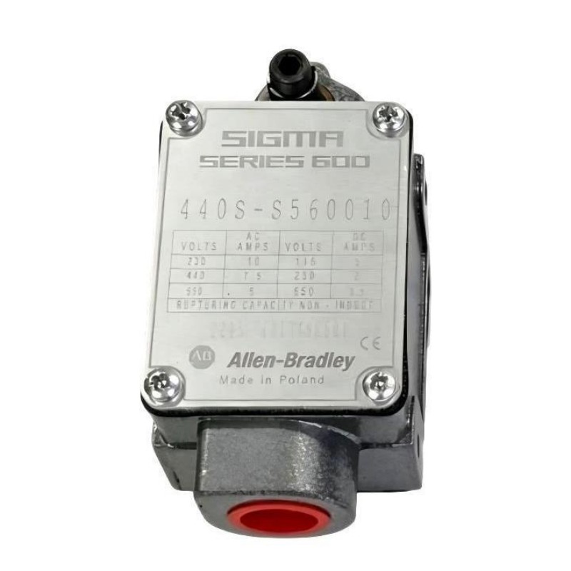
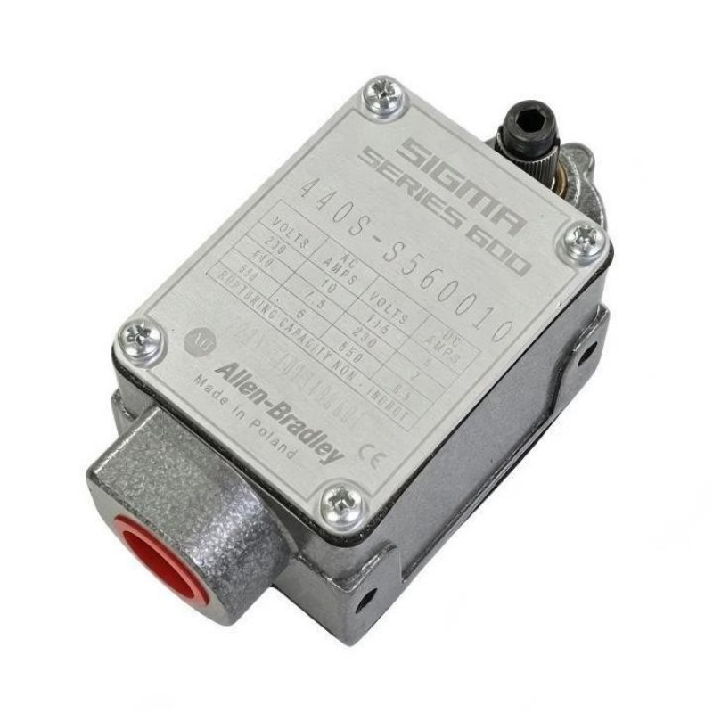
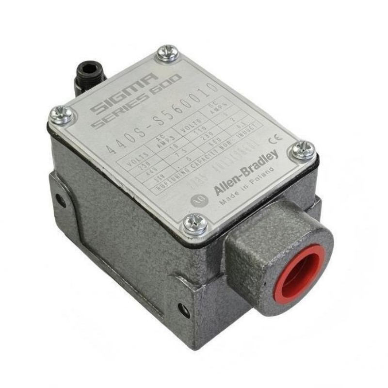
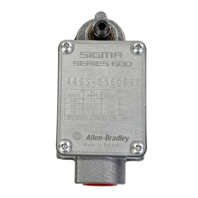
- Allen Bradley
- 440S-S560010
- Snaplock Limit Switch
- USA
- 114 × 83 × 76 mm
- 1.06 kg
- Xiamen, China
- New & In Stock
- T/T, PayPal, Western Union
- 1 Year
- 1-3 Working Days
- DHL, UPS, TNT, FedEx and EMS.
- 24-Hour Service
- COO
- 19
Our advantage

Global Logistics
We have a 10-year logistics and express cooperation agreement, so our products can be shipped to any place in the world.

Brand new and original
Our products are imported in bulk from the place of origin. Because of the cooperative relationship, our products are all original and 100% new.

24-hour service
We provide 7*24 hours service to our customers. We will be there whenever you need us.

Price advantage
All our products are priced very favorably because we have our own warehouse and supply.
| Company Information | |||
| [email protected] | |||
| Mobile | +8615980777398 | ||
| +8615980777398 | |||
| 15980777398 |
Product Overview
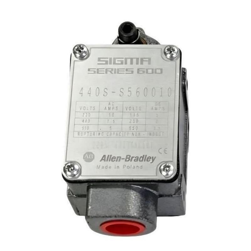
The Allen Bradley 440S-S560010 Snaplock Limit Switch is a mechanically operated rotary limit switch from the 600 series. It detects movement at a defined mechanical position and changes the state of its electrical contacts when the actuator reaches the switching point. In industrial machinery, this type of switch is useful when a control system needs a direct indication that a moving part has reached a travel limit or a particular operating position.
Consider a machine with a rotating shaft, moving carriage, or mechanically driven positioning assembly. As the mechanism reaches a preset point, a cam or linkage actuates the switch. The contacts change state, allowing a relay or controller input to register the position and initiate the next step, stop a movement, or signal that a travel boundary has been reached.
The 440S-S560010 is the standard-contact version in the Snaplock range, with one normally open (NO) contact and one normally closed (NC) contact. These complementary contact states can support different control-circuit arrangements. For example, one contact may signal a position to a controller while the other is incorporated into a separate indication or interlocking circuit, provided the circuit design and contact ratings are appropriate.
The switch uses a mechanical actuation mechanism rather than electronic proximity sensing. Its operation therefore depends on the physical relationship between the actuator and the moving machine component. Cam position, direction of rotation, actuation travel, and mechanical alignment all affect the point at which switching occurs. Correct setup is especially important when the switch is used to define an end position or coordinate a sequence of machine movements.
The 600 series Snaplock range includes different contact arrangements and switching variants. The standard 440S-S560010 should not be confused with neutral-position or tandem versions, which use different contact configurations. Selecting the correct arrangement matters when a machine relies on a particular combination of normally open and normally closed signals.
For maintenance engineers, useful inspection points include the actuator mechanism, mounting security, contact operation, cable entry, and enclosure condition. If a machine intermittently fails to recognize a travel limit, the cause may be mechanical misalignment, actuator wear, loose wiring, or a problem in the receiving control circuit. Checking the switch and its mechanical interface together helps isolate the fault.
Technical Specifications
| Parameter | Specification |
|---|---|
| Manufacturer | Allen-Bradley |
| Model | 440S-S560010 |
| Product Type | Snaplock Limit Switch |
| Product Family | 600 Series |
| Switch Configuration | Standard switch |
| Contact Arrangement | 1 normally open (NO), 1 normally closed (NC) |
| Operating Principle | Mechanical rotary actuation |
| Enclosure Protection | IP66 |
| Standard Operating Temperature | -20°C to +75°C |
| High-Temperature Version Range | Up to +150°C for applicable versions |
| Typical Mechanical Life | 20 million operations |
| Continuous Current Rating | 10 A, subject to applicable electrical rating conditions |
| AC Circuit Voltage Categories | 240 V, 440 V, 550 V |
| DC Circuit Voltage Categories | 115 V, 330 V, 550 V |
| Electrical Life | Depends on the switched load |
| Dimensions | 114 × 83 × 76 mm |
| Weight | 1.06 kg |
Product Features
- Standard NO/NC contact arrangement: Provides one normally open and one normally closed contact for control-circuit switching.
- Mechanical rotary actuation: Detects machine movement through direct physical interaction with a compatible actuator or mechanism.
- 600 series construction: Fits applications using the corresponding Snaplock limit-switch platform.
- IP66 enclosure protection: Helps protect the switch against dust ingress and powerful water jets under specified test conditions.
- Defined switching positions: Supports machine sequencing and travel-limit detection when correctly positioned.
- Long mechanical operating life: The product documentation specifies a typical mechanical life of 20 million operations.
- Industrial electrical switching: Supports control circuits within the applicable contact voltage and current ratings.
- Separate contact functions: Allows the NO and NC contacts to be used for different control or indication purposes when the circuit design permits.
Working Principle
The 440S-S560010 converts mechanical movement into an electrical contact-state change. A rotating cam, shaft, linkage, or compatible actuator moves the switch mechanism. At the defined operating point, the internal switching mechanism changes the state of the NO and NC contacts.
Machine Movement → Mechanical Actuation → Contact-State Change → Control-System Response
When the actuator is not operating the switch, the contacts remain in their normal mechanical states. As the actuator reaches the switching point, the mechanism changes the contact arrangement: the normally open contact closes, and the normally closed contact opens. The connected control circuit can then register the change and respond according to its logic.
For example, a rotary machine may use a cam to operate the switch when a component reaches a defined angular position. The contact transition can provide a position signal to a controller or relay. The control system may then permit the next machine step, change the direction of movement, or initiate a controlled stop.
The switching point depends on the mechanical setup. If the cam is positioned too early, the machine may change state before the intended position is reached. If the switch is actuated too late, the mechanism may travel beyond the desired point. The actuator must provide sufficient movement for reliable switching without exceeding the permitted mechanical travel.
The NO and NC contacts provide complementary electrical states, but they do not independently guarantee a safety function. If the switch is used in a machine-protection circuit, the complete circuit must be assessed for the required safety performance, including the control architecture, fault response, and applicable machinery standards.
The switch’s electrical limits also depend on the type of load. Inductive loads such as relay coils can produce switching transients, while resistive loads behave differently. The contact ratings must be selected according to the applicable voltage, current, and load category rather than treating the maximum current as valid under every operating condition.
Role in an Industrial Machine Control System
The 440S-S560010 acts as a mechanical position-detection device within a control system. It supplies a discrete contact signal when the machine mechanism reaches the configured actuation point. A relay, PLC input, or compatible control circuit can use that signal to determine whether a particular mechanical condition has occurred.
Moving Mechanism → Snaplock Limit Switch → Relay or PLC Input → Machine Sequence
| System Component | Function |
|---|---|
| Allen-Bradley 440S-S560010 | Converts mechanical actuation into an NO/NC contact-state change |
| Cam or Mechanical Actuator | Moves the switch at the selected machine position |
| PLC Digital Input | Reads the contact state for sequence control |
| Control Relay | Uses the switch signal to operate a compatible control circuit |
| Motor Control Circuit | Responds to the machine’s travel or position logic |
| Mechanical Mounting Bracket | Holds the switch in the required position |
| Wiring and Terminals | Connect the switch contacts to the receiving circuit |
| Machine Mechanism | Provides the movement being monitored |
The switch provides a discrete indication of mechanical position rather than continuous position measurement. The receiving control system determines what action follows the contact transition.
Industrial Applications
| Application | Typical Use |
|---|---|
| Material Handling Equipment | Detecting the travel limits of moving mechanisms |
| Packaging Machinery | Signaling the position of cams, indexing mechanisms, or moving assemblies |
| Machine Tools | Detecting a defined mechanical position during a machine cycle |
| Conveyor Systems | Monitoring the position of moving or indexing components |
| Rotary Machinery | Detecting a preset shaft or cam position |
| Automated Assembly | Confirming that a fixture or mechanism has reached a defined point |
| Industrial Lifting Equipment | Providing position signals within a suitably engineered control system |
| Transfer Mechanisms | Coordinating movement between loading and unloading positions |
| Mechanical Sequencing Systems | Triggering the next control step when a linkage reaches its actuation point |
| General Industrial Equipment | Providing discrete position feedback to relay or PLC control circuits |
The switch is most suitable where a machine provides a compatible mechanical actuation point and the control system requires a discrete position signal. Applications with high switching frequency, significant vibration, or safety-related requirements need appropriate mechanical setup and circuit design.
Installation and Maintenance
- Inspect the switch assembly: Check the enclosure, actuator interface, mounting points, and cable-entry area for visible damage before installation.
- Position the switch correctly: Align the actuator with the cam or moving mechanism so that switching occurs at the intended machine position.
- Secure the mounting hardware: Prevent movement of the switch body during operation, as mounting shifts can alter the switching point.
- Set the actuation travel: Provide enough movement for consistent contact operation without forcing the mechanism beyond its permitted travel.
- Check the direction of actuation: Confirm that the cam or linkage operates the switch in the intended direction and returns correctly when the mechanism moves away.
- Identify the NO and NC contacts: Wire each contact according to the machine’s control schematic and intended signal function.
- Select suitable circuit protection: Apply appropriate protection and ensure that the connected load remains within the relevant electrical ratings.
- Inspect cable entries and wiring: Maintain the enclosure’s intended protection by securing cable entries and preventing damage to conductors.
- Test contact transitions: Operate the mechanism manually under safe conditions and confirm that the NO and NC contacts change state correctly.
- Verify machine sequencing: Test the resulting control response to ensure that the contact transition occurs at the intended stage of the machine cycle.
- Inspect for mechanical wear: Check for loose mounting, damaged actuator components, contamination, or changes in switching behavior during scheduled maintenance.
- Record inspection results: Document the contact test, mounting condition, wiring changes, and any corrective work.
If switching becomes intermittent, inspect the mechanical actuator and contact wiring before replacing the switch. A poorly aligned cam or loose mounting bracket can cause the same symptoms as an electrical contact problem.
Related Components
| Component | Function |
|---|---|
| Allen-Bradley 440S-S560010 | Standard Snaplock limit switch with 1 NO and 1 NC contact |
| Mechanical Cam | Operates the switch at a defined rotational position |
| Actuating Linkage | Transfers movement from the machine mechanism to the switch |
| Mounting Bracket | Maintains the switch’s position relative to the actuator |
| Control Relay | Uses the contact signal to operate a compatible control circuit |
| PLC Digital Input Module | Reads the switch state for machine sequencing |
| Control Cable | Connects the switch contacts to the receiving circuit |
| Terminal Block | Provides organized wiring connections inside the control enclosure |
| Circuit Protection Device | Protects the connected control circuit according to its electrical design |
Recommended Related Models
| Model | Product Type | Contact Arrangement / Application |
|---|---|---|
| Allen-Bradley 440S-S560010 | Snaplock Limit Switch | Standard configuration with 1 NO and 1 NC contact |
| Allen-Bradley 440S-S560118 | Snaplock Limit Switch | Neutral-position variant with 2 NO contacts |
| Allen-Bradley 440S-S560337 | Snaplock Limit Switch | Tandem variant with 2 NO and 2 NC contacts |
| Allen-Bradley 440S-S560373 | Snaplock Limit Switch | Tandem neutral-position variant with 4 NO contacts |
| Allen-Bradley 440S-S560226 | Snaplock Limit Switch | Centre-connection switch variant |
| Allen-Bradley 440S-S471161 | Snaplock Limit Switch | Related 600 series switch configuration |
Key Advantages
- Provides discrete mechanical position detection for industrial machinery.
- Offers complementary NO and NC contact states.
- Supports rotary actuation from a cam, shaft, or compatible linkage.
- Uses an IP66 enclosure for demanding industrial environments.
- Has a documented typical mechanical life of 20 million operations.
- Integrates with suitable relay and PLC control circuits.
Technical FAQs
How do the NO and NC contacts behave when the switch is actuated?
The standard 440S-S560010 has one normally open and one normally closed contact. When the mechanism operates the switch, the NO contact closes and the NC contact opens. The receiving control circuit can use these state changes for position indication or machine sequencing.
Can the 440S-S560010 measure the continuous position of a moving shaft?
No. It is a discrete mechanical limit switch, not a continuous position transducer. It indicates that the actuator has reached a switching point. Applications requiring continuous angular or linear measurement need a suitable encoder or position sensor.
What should be considered when switching an inductive load?
Inductive loads can generate voltage transients when the contacts open. The circuit must follow the applicable contact ratings and use suitable suppression or interface components where required. Permitted current depends on the voltage and load category, so the continuous-current figure should not be treated as a universal switching limit.
Is the switch suitable for use in a machine safety circuit?
Its suitability depends on the required safety function and the design of the complete control system. A standard limit switch contact arrangement does not, by itself, establish a particular safety performance level. The switch, circuit architecture, diagnostics, and applicable machinery requirements must all be considered.