

ProductPRODUCT
Featured products
Contact Us
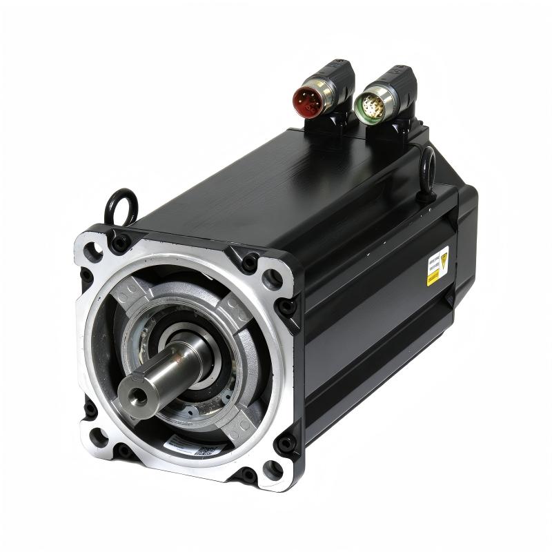
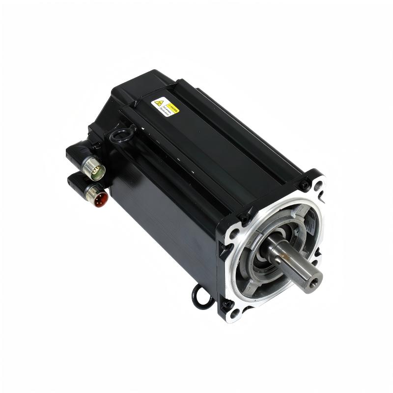
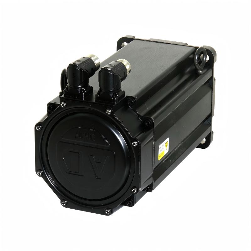
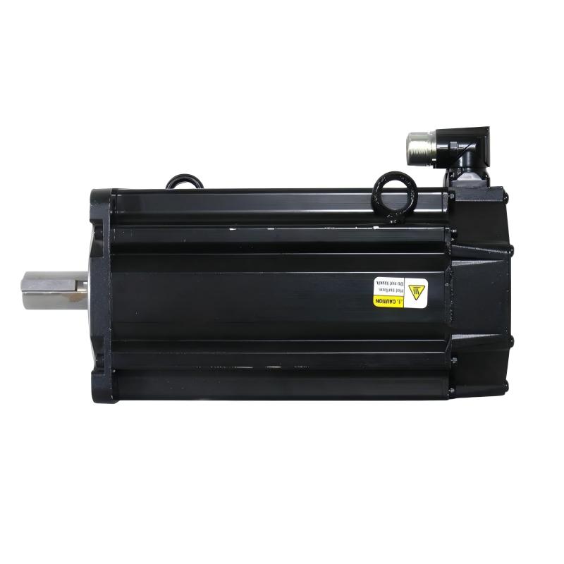
- Allen Bradley
- MPM-B1652C-SJ74AA
- Servo Motor
- USA
- 165 mm
- 20.6 kg
- Xiamen, China
- New & In Stock
- T/T, PayPal, Western Union
- 1 Year
- 1-3 Working Days
- DHL, UPS, TNT, FedEx and EMS.
- 24-Hour Service
- COO
- 2
Our advantage

Global Logistics
We have a 10-year logistics and express cooperation agreement, so our products can be shipped to any place in the world.

Brand new and original
Our products are imported in bulk from the place of origin. Because of the cooperative relationship, our products are all original and 100% new.

24-hour service
We provide 7*24 hours service to our customers. We will be there whenever you need us.

Price advantage
All our products are priced very favorably because we have our own warehouse and supply.
| Company Information | |||
| [email protected] | |||
| Mobile | +8615980777398 | ||
| +8615980777398 | |||
| 15980777398 |
1. Product Overview
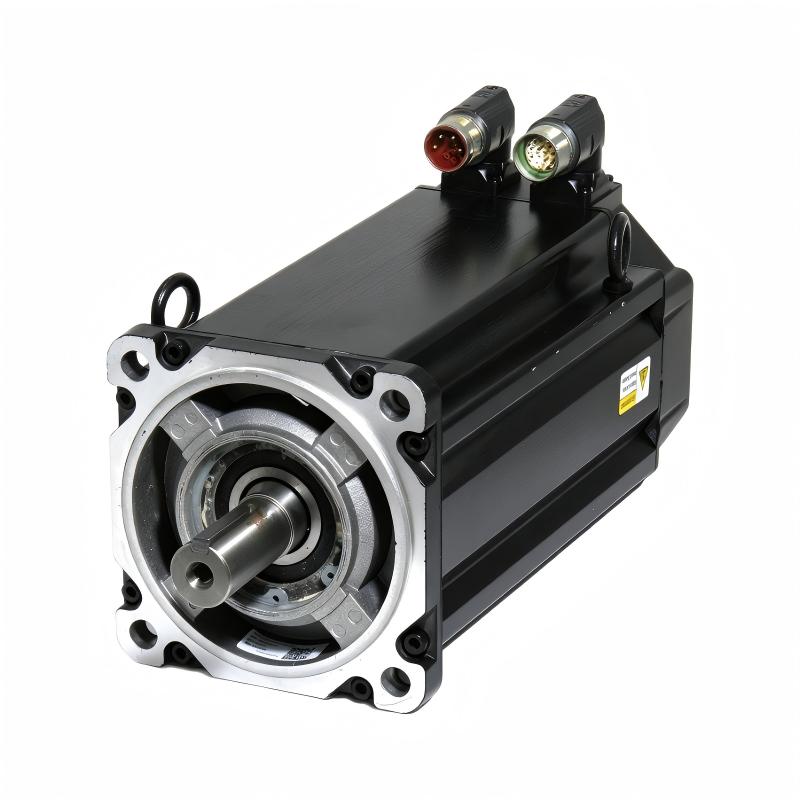
The Allen-Bradley MPM-B1652C-SJ74AA is a medium-inertia rotary servo motor from the MP-Series MPM product family manufactured by Rockwell Automation. Designed for demanding industrial motion-control applications, this motor combines controlled rotational motion, encoder-based feedback, and an integrated holding brake to support machinery that requires reliable positioning, torque delivery, and coordinated movement.
Featuring a 165 mm frame size, a two-stack magnet configuration, and a 460 V AC voltage class, the MPM-B1652C-SJ74AA is intended for integration with compatible industrial servo drives and motion-control systems. Its medium-inertia design makes it a candidate for applications in which the motor must work with a mechanically substantial load while maintaining controlled acceleration, deceleration, and positioning performance.
The motor has a nominal speed designation of 1,500 RPM and supports higher operating speeds under the appropriate drive and load conditions. Its single-turn high-resolution encoder provides position feedback to the servo drive, allowing the control system to regulate motion according to programmed commands. A keyed shaft extension supports compatible mechanical couplings, while the integrated 24 V DC brake can help hold a stationary axis when correctly configured.
The model also features a right-angle SpeedTEC DIN quick-connect connector that can be rotated to accommodate different installation arrangements. This design can help simplify cable routing in industrial machinery where access and enclosure space are important considerations.
The MPM-B1652C-SJ74AA is suitable for evaluation in automated manufacturing equipment, packaging machinery, material-handling systems, and other industrial applications requiring controlled rotary motion. Successful operation depends on correct drive selection, feedback compatibility, mechanical installation, brake control, and commissioning.
For maintenance engineers, system integrators, OEMs, and industrial spare-parts purchasers, confirming the complete model number is essential. Servo motors in the same product family may share similar dimensions while differing in speed, encoder type, shaft design, or brake configuration.
2. Technical Specifications
| Parameter | Specification |
|---|---|
| Manufacturer | Allen-Bradley / Rockwell Automation |
| Product Series | MP-Series MPM Medium-Inertia Servo Motors |
| Model Number | MPM-B1652C-SJ74AA |
| Product Type | Brushless rotary servo motor |
| Frame Size | 165 mm |
| Magnet Stack Configuration | Two magnet stacks |
| Voltage Class | 460 V AC |
| Nominal Speed Designation | 1,500 RPM |
| Maximum Operating Speed | Up to 2,500 RPM, subject to operating conditions and drive configuration |
| Continuous Stall Torque | Approximately 16 Nm |
| Peak Stall Torque | Approximately 40 Nm |
| Continuous Output Power | Approximately 3.8 kW at rated operating conditions |
| Feedback Type | Single-turn high-resolution encoder |
| Shaft Configuration | Keyed shaft extension |
| Integrated Brake | Yes |
| Brake Voltage | 24 V DC |
| Power Connector | SpeedTEC DIN quick-connect |
| Connector Arrangement | Right-angle connector, rotatable up to 180° |
| Mounting Configuration | IEC metric, free mounting holes, Type FF |
| Product Weight | Approximately 20.6 kg |
| Motor Construction | Permanent-magnet, brushless, medium-inertia design |
| Typical System Application | Closed-loop industrial servo motion control |
Specification note: The nominal speed, maximum operating speed, continuous torque, peak torque, and output power refer to different operating conditions and should not be interpreted as simultaneously available ratings. Actual performance depends on the compatible drive, load profile, cooling conditions, and the applicable motor documentation. The 20.6 kg figure is the supplied product weight; confirm packaging weight separately when arranging transportation.
3. Function and Working Principle
3.1 Brushless Servo Motor Technology
The MPM-B1652C-SJ74AA converts electrical energy into controlled mechanical rotation. Its permanent-magnet rotor interacts with the magnetic field generated by the stator windings to produce torque.
A compatible servo drive regulates the current supplied to the motor windings. By controlling the magnitude and timing of the current, the drive can regulate motor torque, speed, and direction. The motion controller provides commands based on the machine’s operating sequence, while feedback allows the drive to monitor the actual motion response.
This closed-loop arrangement differs from a basic open-loop motor installation. Rather than relying only on a fixed electrical supply, the servo system continuously evaluates motion feedback and adjusts its output to reduce the difference between commanded and actual behavior.
The result is controlled movement that can support repeatable positioning, coordinated axes, and automated operating sequences.
3.2 Medium-Inertia Motor Design
The MPM product family is designed for applications that benefit from a medium-inertia motor configuration. Motor inertia influences how quickly the rotor responds to changes in torque and speed. It also affects the relationship between motor dynamics and the inertia of the connected machine.
A medium-inertia motor may be appropriate where the mechanical load is relatively substantial or where the application requires a balance between dynamic response and load characteristics. However, the suitability of a motor cannot be determined by inertia alone.
Engineers should evaluate the complete system, including:
- Motor rotor inertia.
- Reflected load inertia.
- Gearbox or belt transmission ratio.
- Required acceleration and deceleration.
- Operating cycle and duty requirements.
- Load torque, friction, and external forces.
- Servo drive current and overload capability.
Proper sizing helps the motor operate within its specified limits and reduces the risk of excessive current, poor dynamic performance, or unwanted mechanical stress.
3.3 Encoder Feedback and Motion Regulation
The MPM-B1652C-SJ74AA uses a single-turn high-resolution encoder. This feedback device supplies rotor-position information to the compatible drive so that the control system can regulate the motor’s motion.
Encoder feedback supports several important control functions:
- Position regulation.
- Velocity regulation.
- Motor commutation.
- Motion monitoring.
- Detection of certain feedback or motion faults.
A single-turn encoder measures angular position within one revolution. It should not be assumed to provide the same multi-turn absolute-position functionality as an encoder designed to track position across multiple revolutions.
For machinery that requires absolute multi-turn position information after a power interruption, the feedback configuration and machine homing strategy must be checked carefully before selecting a motor.
3.4 Integrated 24 V DC Holding Brake
The SJ74AA configuration includes a 24 V DC brake. In a typical servo application, the brake is used to help hold the motor shaft when the motor is stopped and the brake is engaged.
The brake is not a substitute for the servo drive’s normal motion-control function, and it should not automatically be treated as a dynamic stopping brake. Its permitted use, holding capacity, engagement timing, and release conditions must follow the manufacturer’s requirements.
Applications involving vertical axes, suspended loads, or other gravity-loaded mechanisms require particular attention to brake sizing and safety design. The complete machine may require additional mechanical safeguards, safety-rated controls, or an independent load-holding arrangement.
3.5 Speed and Torque Characteristics
The MPM-B1652C motor configuration is associated with a nominal speed designation of 1,500 RPM and a maximum operating speed of up to 2,500 RPM under the appropriate operating conditions.
Its reference continuous stall torque is approximately 16 Nm, while peak stall torque is approximately 40 Nm. These values describe different operating conditions. Peak torque is generally available only within specified limits and for a limited duration.
For practical motor selection, engineers should evaluate the complete torque-speed curve, the required continuous torque, peak load events, acceleration demands, and the drive’s electrical capability. A suitable design must meet the application’s requirements without exceeding the motor’s thermal or mechanical limits.
4. Role in Industrial Automation Systems
The MPM-B1652C-SJ74AA functions as an actuator in a larger motion-control architecture. It works with a compatible servo drive, controller, feedback wiring, power cables, and mechanical transmission to convert motion commands into controlled machine movement.
4.1 Precision Positioning
Positioning applications require a motor to move a load to a specified location and repeat the movement according to the programmed sequence. The encoder provides feedback that allows the servo drive to regulate rotor position.
This capability can be useful in indexing equipment, automated assembly stations, transfer mechanisms, and machinery that must repeatedly position components.
Actual positioning performance depends on the full system, including the encoder, controller, mechanical stiffness, backlash, coupling, tuning, and external load.
4.2 Controlled Speed and Rotation
In speed-control applications, the drive regulates motor velocity according to the commanded operating profile. This is useful for rotary machinery, feed systems, material-processing equipment, and other installations where consistent speed is important.
The motor’s speed range must be evaluated against the required operating point and load torque. Maximum speed alone does not determine the power available at that speed.
4.3 Coordinated Motion Control
Industrial machinery often contains multiple axes that must operate in a coordinated sequence. A compatible motion controller can coordinate servo axes according to programmed position, speed, and timing requirements.
The MPM-B1652C-SJ74AA may serve as one axis within such a system when its mechanical and electrical characteristics are suitable. Multi-axis performance depends on the controller architecture, drive compatibility, network configuration, and application programming.
4.4 Holding a Stationary Axis
The integrated 24 V DC brake provides a holding function when used according to the manufacturer’s instructions. It may be useful in applications where the shaft must remain stationary when the motor is not actively producing motion.
Brake operation must be integrated with the drive and machine sequence. The brake should not be released or engaged without considering the load, motor torque, and potential for uncontrolled movement.
4.5 Maintenance and Equipment Replacement
Industrial servo motors may require replacement due to bearing wear, electrical damage, encoder faults, contamination, connector problems, or general service-life considerations.
When replacing an MPM-B1652C-SJ74AA, maintenance teams should compare the full catalog number, nameplate information, shaft configuration, encoder type, brake option, and connector arrangement. A motor with the same frame size may still require different cables, drive parameters, or mechanical modifications.
Correct identification before ordering can reduce installation delays and avoid compatibility problems during commissioning.
5. Industrial Applications
5.1 Automated Packaging Machinery
Packaging systems often require precise rotary motion to coordinate product feeding, sealing, cutting, indexing, and transfer. Servo control supports programmable movement profiles and can accommodate changes in production speed or product format.
The MPM-B1652C-SJ74AA may be considered for suitable machine axes when its torque, speed, inertia, and feedback characteristics meet the application’s requirements.
The integrated brake may also be relevant to a machine design that requires the shaft to be held under defined stationary conditions.
5.2 Material Handling and Transfer Systems
Material-handling machinery may use servo motors to operate transfer units, rotary tables, positioning mechanisms, and automated handling equipment.
Medium-inertia motor designs can be evaluated for applications with substantial moving components. Correct sizing should account for the payload, transmission ratio, friction, acceleration profile, and expected operating cycle.
For vertical or gravity-loaded axes, the brake and independent safety provisions must be evaluated as part of the complete system.
5.3 Industrial Assembly Equipment
Automated assembly systems often require repeatable movement to position components, operate fixtures, and coordinate multiple production steps. Encoder-based servo control can support the required movement profiles.
Possible application areas include automated workstations, rotary indexing mechanisms, component transfer equipment, and specialized manufacturing machinery.
The final selection should consider positioning requirements, load dynamics, duty cycle, and the controller’s supported feedback and drive interfaces.
5.4 Printing and Converting Machinery
Printing, labeling, winding, and converting equipment may require synchronized rotation and controlled acceleration. Motion errors can affect material registration, product spacing, or process consistency.
A properly configured servo system can coordinate the motor with other machine axes. The application must be sized for the actual material load, transmission characteristics, and required motion profile.
5.5 Industrial Processing Equipment
Industrial processing machines can use servo motors for rotary mechanisms, controlled feed systems, and automated adjustment axes. The MPM-B1652C-SJ74AA may be considered where its speed and torque characteristics fit the process.
Engineers should also consider environmental conditions, contamination protection, mounting rigidity, temperature, and the accessibility of the motor and cables for maintenance.
5.6 OEM Machinery and System Integration
Original equipment manufacturers may incorporate servo motors into custom machinery that requires programmable motion and integration with an industrial control system.
The MPM-B1652C-SJ74AA can be evaluated as part of an Allen-Bradley motion-control solution when the selected drive, feedback interface, controller, and mechanical arrangement are compatible.
Before finalizing the design, confirm the motor’s electrical requirements, brake-control method, cable set, and motion-controller configuration.
6. Installation and System Integration
Correct installation is essential for safe operation, reliable motion performance, and long service life. Installation and commissioning should be carried out by qualified personnel using the applicable manufacturer documentation and site safety procedures.
6.1 Mechanical Mounting
Before installation, inspect the motor flange, mounting holes, keyed shaft, connector, and external housing. The machine structure must provide adequate support and maintain alignment under operating loads.
Key considerations include:
- Confirming the 165 mm frame and the required mounting arrangement.
- Verifying the flange dimensions and fastener specifications.
- Checking shaft dimensions and the keyway configuration.
- Selecting a compatible coupling or transmission.
- Aligning the motor shaft with the driven equipment.
- Avoiding excessive radial or axial shaft loading.
- Ensuring that the motor is securely mounted.
- Providing access for inspection and maintenance.
The keyed shaft must be matched to a suitable coupling. The key, shaft, and coupling should be inspected for wear or damage before the system is operated.
6.2 Power and Feedback Wiring
The motor requires compatible power and feedback cables connecting it to the servo drive. The selected cables must match the connector arrangement, electrical ratings, feedback interface, and installation requirements.
Before energizing the equipment, verify:
- Motor and drive catalog numbers.
- Motor power-cable compatibility.
- Feedback cable and connector pinout.
- Protective grounding and bonding.
- Cable shielding and routing.
- Separation between motor power cables and sensitive signal wiring.
- Connector locking and strain relief.
- The correct drive configuration for the motor.
A connector that physically fits does not necessarily guarantee electrical compatibility. Incorrect wiring may damage the motor, feedback device, or servo drive.
6.3 Servo Drive Compatibility
The servo drive must support the motor’s voltage class, current requirements, encoder feedback, and brake configuration. The drive should be selected using the exact motor catalog number and the applicable compatibility documentation.
Engineers should confirm:
- Supported motor series and model.
- Voltage and current ratings.
- Feedback type and communication requirements.
- Compatible power and feedback cables.
- Drive firmware and configuration requirements.
- Controller and network compatibility.
- Brake-control support and wiring requirements.
- Motor parameter and commissioning procedures.
Do not assume that every drive in the same product family supports every MPM motor configuration.
6.4 Brake Wiring and Control
The integrated brake operates at 24 V DC. Its control circuit must meet the manufacturer’s electrical requirements, including the correct voltage, current, polarity where applicable, and switching arrangement.
The brake’s function should be coordinated with the servo drive and machine sequence. In a typical application, the motor should be managed so that the load is appropriately supported before the brake is released, and the brake is engaged according to the prescribed stopping and holding procedure.
For gravity-loaded axes or applications where unintended movement could cause injury or damage, a formal risk assessment and suitable safety measures are required. The motor’s integrated brake alone should not be treated as a complete safety system.
6.5 Connector Orientation and Cable Routing
The right-angle SpeedTEC DIN connector can be rotated to suit different installation layouts. This can help reduce interference with nearby equipment and support cable routing in compact machine enclosures.
Select the connector orientation before completing the cable installation. Avoid excessive bending, tension, twisting, or mechanical loading on the connector.
Cables should be routed away from moving components, sharp edges, hot surfaces, and sources of electrical interference. Ensure that the final installation maintains adequate access for inspection and service.
6.6 Commissioning and Testing
Before production operation, carry out commissioning checks in accordance with the applicable manufacturer instructions and site procedures.
Recommended checks include:
- Confirming the motor catalog number and nameplate ratings.
- Inspecting the mounting hardware and mechanical coupling.
- Verifying the power and feedback connections.
- Confirming correct feedback recognition by the drive.
- Checking motor rotation direction.
- Testing brake engagement and release according to the approved procedure.
- Verifying the drive configuration and motion parameters.
- Testing the axis at a controlled operating level where appropriate.
- Checking for abnormal vibration, noise, temperature, or current.
- Validating machine interlocks and safety functions.
Any unexpected motion, brake fault, feedback error, or abnormal operating condition should be investigated before the machine is returned to normal production.
7. Compatible System Components
The MPM-B1652C-SJ74AA is part of a servo motion-control system rather than a stand-alone control device. The following component categories should be evaluated when planning an installation or replacement.
| Component | Function | Selection Considerations |
|---|---|---|
| Compatible Allen-Bradley servo drive | Controls motor current, torque, speed, and position | Confirm voltage class, current capacity, feedback compatibility, and motor support |
| Motion controller | Generates motion commands and coordinates machine axes | Verify the supported control architecture and communication interface |
| Motor power cable | Supplies controlled electrical power from the drive | Match the connector, current rating, cable length, and installation requirements |
| Feedback cable | Transfers encoder information to the drive | Confirm the feedback interface, connector pinout, shielding, and cable compatibility |
| Brake-control circuit | Controls the integrated 24 V DC brake | Verify the required electrical ratings, timing, and approved control arrangement |
| Mechanical coupling | Transfers motor torque to the load | Match the keyed shaft, torque requirements, alignment, and operating conditions |
| Mounting hardware | Secures the motor to the machine | Confirm flange dimensions, fasteners, and structural rigidity |
| Protective grounding system | Provides the required electrical bonding | Follow manufacturer instructions and applicable electrical regulations |
These are component categories, not a guarantee that any specific drive or accessory is directly compatible. Confirm exact catalog numbers and wiring requirements before ordering or installation.
8. Recommended Alternative Models and Replacement Considerations
The following models may be considered during replacement planning or system redesign. They have different configurations and must not be treated as automatic drop-in substitutes.
| Model | Main Configuration | Key Difference to Verify |
|---|---|---|
| MPM-B1652C-SJ74AA | 165 mm frame, 1500 RPM nominal designation, single-turn encoder, keyed shaft, 24 V DC brake | Original reference configuration |
| MPM-B1652C-SJ72AA | Similar frame and speed configuration, single-turn encoder, keyed shaft | No integrated brake |
| MPM-B1652C-MJ74AA | Similar frame and speed configuration, multi-turn high-resolution encoder, keyed shaft, brake | Multi-turn feedback instead of single-turn feedback |
| MPM-B1652E-SJ74AA | Similar frame family, 2250 RPM nominal designation, single-turn encoder, keyed shaft, brake | Different speed and performance characteristics |
| MPM-B1652F-SJ74AA | Similar frame family, 3000 RPM nominal designation, single-turn encoder, keyed shaft, brake | Different speed rating and operating characteristics |
Before selecting a replacement, compare voltage class, speed, torque, output power, feedback type, shaft configuration, brake option, connector arrangement, mounting dimensions, and drive compatibility.
A model with a multi-turn encoder may require different drive configuration or machine-positioning procedures. A motor without a brake may be unsuitable for an application that depends on the original brake function. Likewise, a motor with a different speed rating may require a revised motion profile or a new application assessment.
The final replacement decision should be based on the full catalog number, the existing machine design, and the applicable technical documentation.
9. Key Advantages
Medium-Inertia Design
The MPM family provides medium-inertia servo motor options for industrial motion applications. Correctly matching motor and load inertia can help achieve stable and predictable motion performance.
High-Resolution Encoder Feedback
The single-turn high-resolution encoder supports closed-loop motion regulation. Correct integration allows the drive to use rotor-position feedback for commutation and motion control.
Integrated Holding Brake
The 24 V DC brake provides a holding function when correctly controlled and used within its rated conditions. This can be useful in applications that require the motor shaft to remain stationary during designated operating states.
Keyed Shaft Extension
The keyed shaft provides a defined mechanical interface for compatible couplings and transmission components. Proper shaft and coupling selection is necessary to prevent excessive wear and mechanical damage.
Flexible Connector Orientation
The rotatable right-angle SpeedTEC DIN connector provides flexibility for cable routing in different machine layouts. Proper connector positioning can simplify installation and maintenance access.
Industrial Motion-Control Integration
The motor is designed for use with compatible Allen-Bradley motion-control equipment. Correct selection of the servo drive, controller, feedback wiring, and brake-control arrangement supports reliable integration.
Suitability for Industrial Maintenance
For facilities already using compatible MP-Series equipment, identifying the correct MPM motor configuration can help simplify spare-parts planning and replacement work. Compatibility should always be confirmed before installation.
10. Technical FAQs
Q1: What is the frame size of the MPM-B1652C-SJ74AA?
The motor has a 165 mm frame size. The full catalog number should be used when confirming mechanical dimensions and replacement compatibility.
Q2: What is the nominal speed of this servo motor?
The model designation corresponds to a nominal speed of 1,500 RPM. The motor can support higher operating speeds, up to approximately 2,500 RPM under the appropriate operating conditions. The applicable torque-speed specifications should be checked before selecting the motor for a particular application.
Q3: Does the MPM-B1652C-SJ74AA include a brake?
Yes. The SJ74AA configuration includes an integrated 24 V DC brake. Brake wiring, control timing, holding capability, and safe use must follow the manufacturer’s instructions.
Q4: What type of feedback does this motor use?
The motor uses a single-turn high-resolution encoder. It should not be assumed to have the same multi-turn absolute-position functionality as a model configured with a multi-turn encoder.
Q5: Is the motor shaft keyed?
Yes. The SJ74AA configuration uses a keyed shaft extension. The shaft dimensions, keyway, coupling, and mounting arrangement should be checked before installation.
Q6: What is the voltage rating?
The model belongs to the 460 V AC voltage class. The integrated brake uses 24 V DC. These are separate electrical specifications, and the brake must be connected through the appropriate control circuit.
Q7: What is the approximate weight?
The supplied product information lists a product weight of approximately 20.6 kg. Packaging and shipping weight may be higher, so freight arrangements should be based on the supplier’s confirmed shipment data.
Q8: Can this motor replace an MPM-B1652C-SJ72AA?
Not necessarily without checking the machine requirements. Both models have similar frame and speed configurations, but the SJ74AA includes a brake while the SJ72AA does not. Brake wiring, holding requirements, drive parameters, and the full motor configuration must be reviewed before substitution.
Q9: Can it be used with any Allen-Bradley servo drive?
No. The selected drive must support the motor’s voltage class, feedback interface, current requirements, and brake configuration. Confirm the exact drive and motor combination in the applicable technical documentation.
Q10: What should be checked before purchasing a replacement motor?
Verify the full catalog number, nameplate, frame size, speed, encoder type, shaft configuration, brake option, connector, and required cables. For an existing installation, also check the current servo drive, controller, and machine parameters.
Q11: Is the integrated brake intended for emergency stopping?
The brake should not automatically be treated as a dynamic stopping brake or as the sole safety device. Its intended function and permitted operating conditions must be confirmed from the manufacturer documentation. The machine’s stopping and safety strategy must be designed for the application risk.
Q12: What should be considered when storing or transporting the motor?
Protect the motor from impact, moisture, contamination, and damage to the shaft, connector, and feedback components. Use appropriate packaging and handling equipment, and follow the supplier’s shipping instructions.
11. Procurement and Replacement Considerations
When purchasing an Allen-Bradley MPM-B1652C-SJ74AA servo motor, the complete catalog number should be included in the purchase inquiry. The product family contains multiple configurations with different speed ratings, feedback options, shaft arrangements, and brake selections.
For a replacement project, request clear photographs of the motor nameplate, shaft, connector, brake wiring interface, and overall housing. These details can help confirm whether the offered motor matches the required configuration.
For new, used, refurbished, or surplus equipment, buyers should clarify the unit’s condition, testing status, warranty terms, return policy, and availability of compatible accessories. If the motor is intended for a production-critical machine, it is advisable to confirm the required drive and cable compatibility before ordering.
International procurement may also require attention to protective packaging, delivery schedules, customs documentation, and shipping weight. The supplied motor weight is approximately 20.6 kg, but the final shipping weight should be confirmed with the supplier.
Before installing a replacement, compare the new motor’s nameplate and configuration with the existing unit. Any difference in encoder type, brake option, shaft, connector, or electrical rating should be reviewed by a qualified engineer before the motor is connected to the machine.
12. Conclusion
The Allen-Bradley MPM-B1652C-SJ74AA is a medium-inertia rotary servo motor designed for industrial applications requiring controlled motion, encoder feedback, and a defined shaft-holding function. Its 165 mm frame, 460 V AC class, 1,500 RPM nominal speed designation, single-turn high-resolution encoder, keyed shaft, and integrated 24 V DC brake are important characteristics for engineers and purchasers to evaluate.
The motor may be suitable for automated packaging equipment, material-handling machinery, assembly systems, and other industrial motion-control applications when its torque, speed, inertia, and feedback characteristics match the load and control requirements.
Reliable operation depends on selecting a compatible servo drive, correctly installing the motor and coupling, integrating the encoder and brake, and completing the required commissioning checks. For maintenance and replacement projects, the full catalog number should always be verified before purchase to avoid configuration mismatches and unnecessary downtime.