

ProductPRODUCT
Featured products
Contact Us
- Allen Bradley
- MPL-B4530K-SJ74AA
- Servo Motor
- USA
- 130 mm
- 7.3 kg
- Xiamen, China
- New & In Stock
- T/T, PayPal, Western Union
- 1 Year
- 1-3 Working Days
- DHL, UPS, TNT, FedEx and EMS.
- 24-Hour Service
- COO
- 1
Our advantage

Global Logistics
We have a 10-year logistics and express cooperation agreement, so our products can be shipped to any place in the world.

Brand new and original
Our products are imported in bulk from the place of origin. Because of the cooperative relationship, our products are all original and 100% new.

24-hour service
We provide 7*24 hours service to our customers. We will be there whenever you need us.

Price advantage
All our products are priced very favorably because we have our own warehouse and supply.
| Company Information | |||
| [email protected] | |||
| Mobile | +8615980777398 | ||
| +8615980777398 | |||
| 15980777398 |
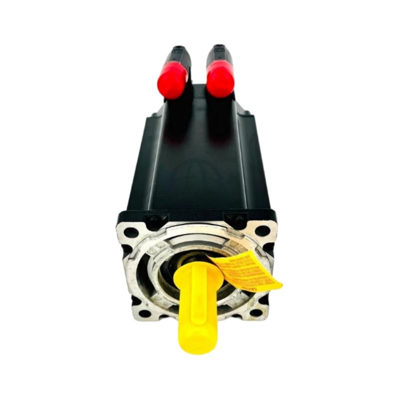
1. Product Overview
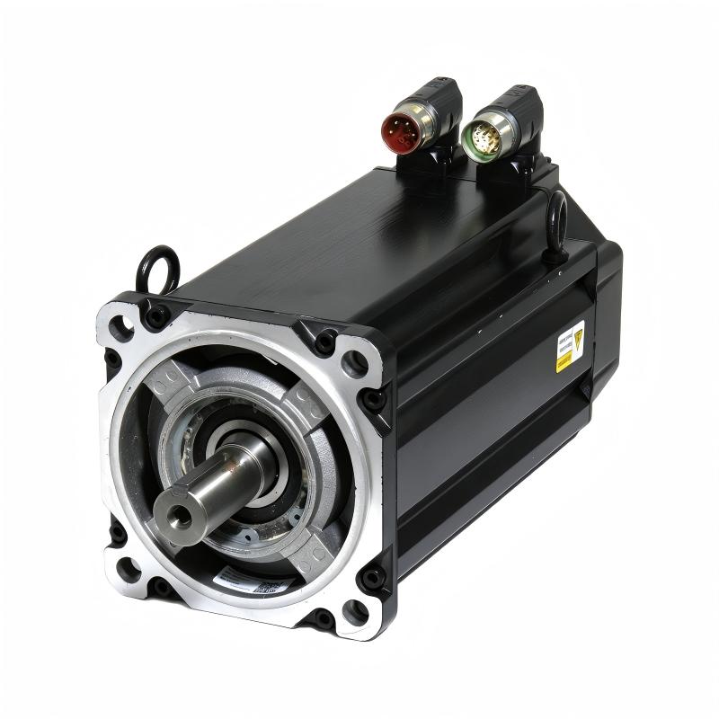
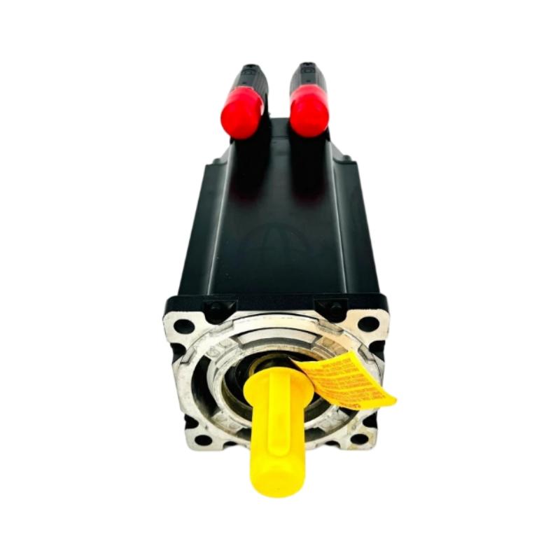
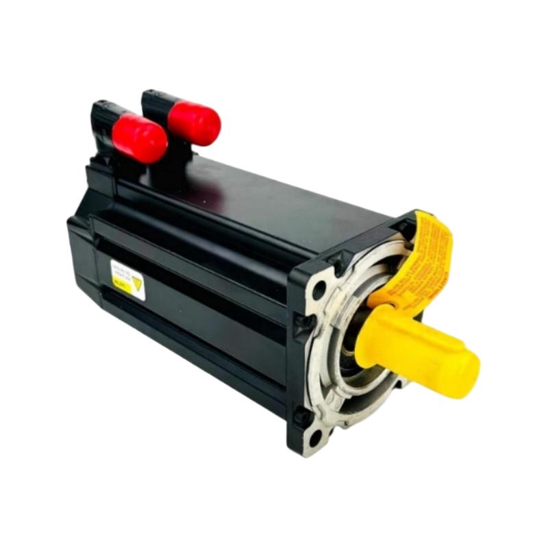
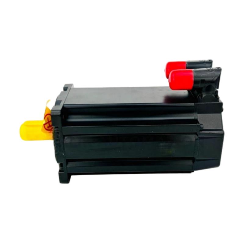
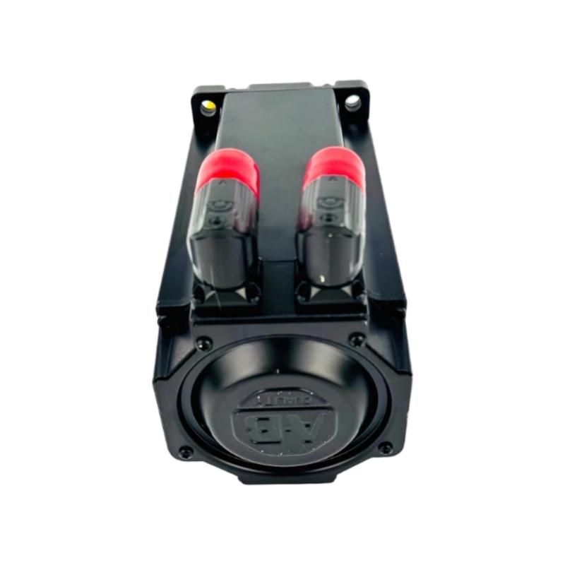
The Allen-Bradley MPL-B4530K-SJ74AA Servo Motor is a low-inertia brushless AC servo motor designed for industrial automation, precision motion control, and automated manufacturing equipment. As part of the Allen-Bradley MP-Series MPL product family, it is intended for use with a compatible servo drive and motion controller to deliver controlled rotational movement in industrial applications.
This model features a 130 mm frame size, a 76.2 mm magnet stack length, and a rated speed of 4000 RPM. It uses a single-turn high-resolution encoder for feedback, a keyed shaft extension for mechanical torque transmission, and a right-angle SpeedTEC DIN connector that can be rotated through 180 degrees. The motor also incorporates a 24 V DC holding brake.
The encoder provides position-related feedback to the compatible servo drive, supporting closed-loop motion control. The drive regulates the electrical power supplied to the motor and adjusts its output according to the motion command and feedback signals. This arrangement can support controlled acceleration, deceleration, speed regulation, and positioning when the complete system is correctly configured.
The integrated 24 V DC brake is an important feature of the MPL-B4530K-SJ74AA. It can provide a holding function for suitable applications when the motor is not actively producing torque. However, the brake must be controlled according to the manufacturer’s instructions and should not automatically be treated as a substitute for a complete machine safety system.
The keyed shaft extension provides a mechanical interface for compatible keyed couplings and driven equipment. This differs from the keyless shaft configuration found on certain related MPL models, so shaft compatibility should be checked carefully when selecting a replacement.
The MPL-B4530K-SJ74AA may be considered for packaging machinery, automated assembly systems, material handling equipment, production lines, and other applications requiring controlled servo motion. Final suitability depends on the required torque, speed, load inertia, duty cycle, drive compatibility, and mechanical installation.
2. Technical Specifications
| Parameter | Specification |
|---|---|
| Brand | Allen-Bradley |
| Product Model | MPL-B4530K-SJ74AA |
| Product Type | Low-Inertia Brushless AC Servo Motor |
| Product Family | MP-Series MPL |
| Frame Size | 130 mm |
| Frame Designation | Frame 45 |
| Magnet Stack Length | 76.2 mm (3.0 in.) |
| Rated Speed | 4000 RPM |
| Voltage Class | 460 V |
| Feedback Type | Single-Turn High-Resolution Encoder |
| Shaft Configuration | Keyed Shaft Extension |
| Connector Type | SpeedTEC DIN Connector |
| Connector Orientation | Right-Angle, 180° Rotatable |
| Brake Configuration | Integrated 24 V DC Brake |
| Mounting Type | IEC Metric Flange |
| Mounting Hole Configuration | Free Mounting Holes, Type FF |
| Weight | 7.3 kg, as supplied |
| Typical Application | Industrial Servo Motion Control |
The specifications above identify the principal configuration of the MPL-B4530K-SJ74AA. The stated weight of 7.3 kg is based on the supplied product information and should be verified against the actual motor before it is used for shipping calculations or equipment-handling plans.
The 460 V voltage class, encoder interface, brake wiring, torque ratings, and operating limits should be checked against the documentation applicable to the specific motor and compatible drive. Frame size and rated speed alone are not sufficient to establish complete electrical or mechanical compatibility.
3. Function and Working Principle
3.1 Brushless AC Servo Motor Operation
The MPL-B4530K-SJ74AA is a brushless AC servo motor designed for controlled motion. It operates with a compatible servo drive that regulates the electrical power supplied to the motor windings.
When the drive receives a command from a motion controller, it determines the required electrical output and produces the motor current needed to generate torque. The motor converts electrical energy into rotational movement, which is transferred through the shaft to the connected mechanical load.
The drive adjusts its output as the commanded position, speed, or torque changes. This allows the motor to accelerate, decelerate, stop, and change direction according to the requirements of the application.
In automated machinery, the motor is therefore part of a coordinated system that includes the servo drive, controller, feedback device, cabling, and mechanical transmission.
3.2 Low-Inertia Design
Low-inertia servo motors are suitable for applications that require responsive changes in speed and direction. A lower rotor inertia can reduce the torque needed to accelerate or decelerate the motor’s own rotating components.
This characteristic can be useful in machinery that performs repeated indexing movements, short positioning cycles, or synchronized operations. For example, an automated assembly machine may need to move a fixture rapidly between workstations and then hold it in a defined position.
Actual system performance depends on more than motor inertia. Load inertia, mechanical stiffness, transmission ratio, coupling alignment, drive tuning, and the controller’s motion profile also affect the response.
The MPL-B4530K-SJ74AA should therefore be selected according to the complete machine requirements rather than frame size alone.
3.3 Single-Turn High-Resolution Encoder Feedback
The MPL-B4530K-SJ74AA uses a single-turn high-resolution encoder. The encoder provides position-related information to the compatible servo drive, allowing the control system to monitor the motor shaft’s angular position within a revolution.
The drive processes this feedback to support motor commutation and closed-loop control. By comparing commanded movement with actual feedback, the drive can adjust motor operation to meet the requested motion profile.
A single-turn encoder differs from a multi-turn absolute encoder in how position is represented across multiple revolutions. Applications requiring absolute position tracking across multiple turns must be evaluated against the encoder capabilities and the overall controller and drive architecture.
When replacing a motor, confirm that the servo drive supports the exact feedback type and protocol. A motor with the same frame size and speed rating may still require different cabling, parameters, or commissioning procedures if its feedback system differs.
3.4 Integrated 24 V DC Holding Brake
The SJ74AA configuration includes an integrated 24 V DC brake. The brake provides a holding function for suitable operating conditions and can help prevent unwanted shaft movement when the motor is not actively generating torque.
In a typical servo application, the brake is released when the axis is commanded to move and is engaged when the axis needs to remain stationary, according to the approved control sequence.
The brake is generally intended for holding rather than repeated dynamic stopping unless the manufacturer’s specifications explicitly permit that use. Its voltage, switching sequence, holding capacity, and duty limitations must be confirmed before commissioning.
For vertical axes or gravity-loaded mechanisms, the brake should be assessed as part of the complete load-holding and safety design. The presence of a brake alone does not guarantee that an application is safe under every failure condition.
3.5 Keyed Shaft Extension
The MPL-B4530K-SJ74AA features a keyed shaft extension. In a keyed shaft arrangement, a key fits between the motor shaft and a compatible coupling or driven component to transmit torque.
The shaft, key, keyway, and coupling must match the mechanical requirements of the application. The coupling should be selected according to shaft dimensions, torque, alignment tolerances, and the expected operating conditions.
A keyed shaft differs from a keyless shaft, which typically relies on a compatible clamping or friction-based coupling arrangement. This distinction is especially important when replacing an installed servo motor.
Correct coupling installation helps reduce vibration, excessive bearing loads, mechanical wear, and the risk of transmission failure.
3.6 Closed-Loop Motion Control
The motor, encoder, servo drive, and motion controller work together to deliver controlled movement.
A typical operating sequence is:
- The controller issues a position, speed, or torque command.
- The servo drive calculates the required electrical output.
- The motor generates torque and rotates the shaft.
- The encoder provides position-related feedback.
- The drive regulates motor operation using the feedback signals.
- The controller coordinates the axis with the rest of the machine.
- The brake is controlled according to the axis state and approved operating sequence.
This coordinated operation supports automated movement while allowing the system to respond to changing commands and load conditions.
4. Role in Industrial Automation Systems
4.1 Integration with Servo Drives
The MPL-B4530K-SJ74AA requires a compatible servo drive that supports its electrical characteristics and single-turn high-resolution encoder feedback.
The drive supplies controlled power to the motor and manages the feedback loop. It must also support the required brake-control arrangement or an appropriate external brake-control interface.
The motor power connections, encoder connections, and brake circuit should be identified and wired according to the applicable documentation. A connector that looks mechanically similar does not necessarily establish electrical compatibility.
4.2 Integration with PLCs and Motion Controllers
A programmable logic controller (PLC) or motion controller coordinates the machine’s operating sequence and issues motion commands to the servo drive.
For example, a controller may command a positioning axis to move a component into an assembly station. The drive regulates the motor, while encoder feedback supports closed-loop movement.
The controller may also monitor drive-ready status, motion completion, alarms, and other diagnostic signals. Brake commands should be coordinated with the axis-control sequence according to the drive and machine design.
This arrangement allows the servo motor to participate in a broader automation system involving sensors, actuators, safety devices, operator interfaces, and supervisory control functions.
4.3 Mechanical Transmission
The motor shaft can drive a compatible gearbox, coupling, belt transmission, screw mechanism, rotary table, or other mechanical assembly.
The transmission converts motor rotation into the required movement of the load. Selection depends on the desired output speed, torque, load inertia, friction, and mechanical arrangement.
Because this model uses a keyed shaft, the mechanical coupling must be designed for the corresponding shaft and key dimensions. Incorrect coupling selection or poor alignment may lead to vibration, bearing stress, and premature wear.
4.4 Brake and Load-Holding Control
The integrated brake adds a holding function to the servo axis. In suitable applications, it can help maintain a stationary position when motor torque is removed.
The brake’s role must be defined within the overall machine-control strategy. The controller and drive should follow the approved release and engagement sequence, and the brake’s actual capacity must be appropriate for the load.
Applications involving suspended loads, vertical axes, or hazardous movement may require additional mechanical safeguards and safety-rated measures based on a formal risk assessment.
4.5 Diagnostics and Maintenance
The servo drive and controller may provide diagnostic information that helps maintenance teams identify feedback faults, electrical problems, motor overloads, or configuration errors.
If the axis fails to move or hold position as expected, the issue may involve the motor, encoder cable, power cable, brake circuit, drive settings, controller logic, or mechanical transmission.
A systematic troubleshooting procedure helps identify the actual cause before a replacement component is installed.
5. Industrial Applications
5.1 Packaging Machinery
Packaging equipment frequently requires repeatable positioning, synchronized movement, and controlled acceleration and deceleration. Servo motors may drive product-feeding mechanisms, sealing units, cutting systems, indexing conveyors, and transfer devices.
The MPL-B4530K-SJ74AA may be considered for compatible axes where its speed, torque characteristics, encoder feedback, keyed shaft, and brake configuration meet the application requirements.
The holding brake may be useful for a suitable axis that needs to remain stationary under defined operating conditions. The machine designer must confirm that the brake is appropriate for the actual load and safety requirements.
5.2 Automated Assembly Systems
Automated assembly lines use servo-driven axes to position components, move fixtures, and coordinate operations between stations.
The encoder supports closed-loop motion control, while the brake provides a holding option for suitable applications. The keyed shaft can connect to mechanical components designed for a keyed interface.
Achievable positioning performance depends on the complete system, including the controller, drive, encoder feedback, transmission, tooling, and mechanical stiffness.
5.3 Material Handling Equipment
Material handling systems may use servo motors for indexing platforms, transfer mechanisms, positioning units, and other controlled movements.
The integrated brake may be relevant when an axis needs a holding function. However, applications involving vertical movement or loads that can move under gravity require particular attention to brake capacity and machine safety.
The brake should not be assumed to provide complete protection against every power-loss or fault condition. The overall load-holding strategy must be engineered for the specific application.
5.4 Machine Tools and Production Equipment
Industrial production machinery may use servo motors to control feed axes, rotary mechanisms, positioning tables, and auxiliary equipment.
The MPL-B4530K-SJ74AA can be evaluated for applications that require its 130 mm frame, 4000 RPM rated speed, single-turn high-resolution encoder, keyed shaft, and 24 V DC brake.
Selection should include continuous and peak torque, acceleration requirements, duty cycle, thermal limits, load inertia, and drive compatibility. These factors determine whether the motor can meet the required operating profile.
5.5 Special-Purpose Automation
Special-purpose machines often require multiple axes to move in a coordinated sequence. A servo motor may operate a transfer unit, rotary mechanism, indexing station, or positioning assembly while the controller coordinates the wider process.
The SJ74AA configuration may suit an axis where the feedback interface is supported and the mechanical coupling matches the keyed shaft.
Connector orientation and cable routing should be considered during system design, especially where installation space is limited.
5.6 Industrial Maintenance and Replacement
When a servo motor fails, the availability of a correctly configured replacement can help reduce production downtime.
For the MPL-B4530K-SJ74AA, the key identification points are the complete model number, single-turn high-resolution encoder, keyed shaft, 24 V DC brake, connector arrangement, and mounting dimensions.
A replacement should not be chosen based only on its frame size or rated speed. A motor with a different feedback device, keyless shaft, or brake configuration may require additional engineering work before it can be installed.
6. Installation and System Integration
6.1 Verify the Complete Model Number
Before installation, compare the motor nameplate with the machine documentation. Confirm that the model is MPL-B4530K-SJ74AA and that its feedback, shaft, connector, and brake configurations match the intended application.
Related MPL motors may share similar dimensions but have different feedback systems or shaft arrangements. The complete model suffix is important when ordering a replacement.
6.2 Check Mechanical Mounting
Confirm the frame size, flange dimensions, mounting-hole pattern, shaft extension, key dimensions, and available installation clearance.
The mounting structure should support the expected mechanical loads and maintain proper alignment between the motor and the driven equipment.
Incorrect alignment, unsuitable couplings, or excessive shaft loading can contribute to vibration, bearing damage, and reduced service life.
6.3 Verify Electrical Compatibility
The servo drive must support the motor’s voltage class and single-turn encoder feedback. Confirm that the motor power cable, encoder cable, connectors, grounding, and shielding are suitable for the system.
The brake circuit requires separate attention. Verify the 24 V DC brake supply and the prescribed switching arrangement.
Do not assume that motor power and brake power use the same circuit. Follow the applicable wiring diagrams and safety procedures.
6.4 Connect the Encoder Feedback
Connect the encoder to the compatible drive feedback interface using the correct cable and connector configuration.
Inspect the connectors for damaged contacts, contamination, loose connections, and mechanical wear. Route feedback cables according to the equipment manufacturer’s recommendations to reduce interference and avoid damage.
After wiring, confirm that the drive recognizes the expected feedback device and that the configured motor parameters are correct.
6.5 Inspect the Keyed Shaft and Coupling
Confirm that the coupling matches the motor shaft and key dimensions. Check torque capacity, alignment tolerances, and fastening requirements.
Avoid forcing the coupling onto the shaft or applying impact loads to the motor bearings. If the original motor uses a keyless shaft, do not assume that its coupling can be reused without checking compatibility.
6.6 Check the Brake Circuit
Inspect the brake wiring, supply voltage, connector condition, and control logic before operation.
Verify that the brake releases and engages according to the prescribed sequence. If the motor does not release correctly, fails to hold as expected, or produces abnormal noise or heating, investigate the cause before returning the machine to production.
The brake should not be treated as an unverified substitute for the machine’s required safety functions.
6.7 Configure and Commission the Drive
Select the correct motor configuration in the compatible servo drive. Confirm that encoder feedback is recognized and that the brake-control settings match the installed motor and machine requirements.
Commissioning may include checking the direction of rotation, axis scaling, acceleration and deceleration limits, current limits, feedback behavior, and brake sequence.
Follow the procedures applicable to the specific drive and controller rather than copying parameters from a different motor model without verification.
6.8 Perform a Controlled Test
Before resuming normal production, perform a controlled test under safe conditions.
The commissioning process should include:
- Verifying the motor model and mechanical installation.
- Checking power, encoder, grounding, and brake connections.
- Confirming the drive configuration and feedback recognition.
- Testing controlled movement at an appropriate speed.
- Checking direction of rotation and axis response.
- Verifying brake release and engagement under approved conditions.
- Inspecting for abnormal noise, vibration, or overheating.
- Confirming machine interlocks and required safety functions.
All installation and commissioning work should be performed by qualified personnel in accordance with applicable safety procedures.
7. Compatible System Components
The MPL-B4530K-SJ74AA is designed to operate within a compatible servo motion-control system. Depending on the machine, the following component categories may be required.
| Component | Function | Compatibility Considerations |
|---|---|---|
| Servo Drive | Regulates motor power and motion | Must support the motor’s electrical characteristics and encoder feedback |
| PLC or Motion Controller | Coordinates axis movement | Must support the selected drive and motion-control architecture |
| Motor Power Cable | Supplies controlled power | Must match the motor connector and drive output |
| Encoder Feedback Cable | Transfers position feedback | Must match the encoder and drive interface |
| Brake Power and Control Circuit | Controls the integrated brake | Must meet the specified 24 V DC brake requirements |
| SpeedTEC DIN Connection | Provides the motor-side electrical interface | Confirm connector and cable configuration |
| Keyed Mechanical Coupling | Transfers torque to the driven load | Must match shaft and key dimensions |
| Gearbox or Transmission | Adapts motor output to the load | Select according to torque, speed, and load inertia |
| Mounting Structure | Supports the motor | Must match flange dimensions and mechanical loads |
| Protective and Safety Devices | Address machine hazards | Must be selected according to the machine risk assessment |
This table describes general system component categories and does not guarantee direct compatibility with every product. Final selection should be based on the installed drive, controller, cabling, mechanical design, and applicable technical documentation.
8. Recommended Alternative Models and Replacement Considerations
Several Allen-Bradley MPL motors share a similar frame size and speed rating, but differences in feedback, shaft design, and brake configuration can affect interchangeability.
| Model | Main Configuration | Replacement Considerations |
|---|---|---|
| MPL-B4530K-SJ74AA | Single-turn high-resolution encoder, keyed shaft, 24 V DC brake | Reference model |
| MPL-B4530K-SJ72AA | Single-turn high-resolution encoder, keyed shaft, no brake | Brake configuration differs |
| MPL-B4530K-SK74AA | Single-turn high-resolution encoder, keyless shaft, 24 V DC brake | Shaft and coupling configuration differ |
| MPL-B4530K-MJ74AA | Multi-turn high-resolution absolute encoder, keyed shaft, 24 V DC brake | Feedback type differs |
| MPL-B4530K-MK74AA | Multi-turn high-resolution absolute encoder, keyless shaft, 24 V DC brake | Feedback and shaft configuration differ |
| MPL-B4530K-RJ74AA | Resolver feedback, keyed shaft, 24 V DC brake | Feedback technology differs |
These models are potential comparison candidates, not guaranteed drop-in replacements. Confirm the complete part number and the applicable technical documentation before selecting an alternative.
8.1 Feedback Compatibility
The reference model uses a single-turn high-resolution encoder. Replacing it with a resolver-feedback or multi-turn absolute-encoder motor may require a different feedback interface, cable, drive configuration, or commissioning process.
The selected drive must support the alternative feedback type and its associated motor configuration.
8.2 Shaft Compatibility
The SJ74AA uses a keyed shaft extension. A keyless-shaft alternative may require a different coupling or approved mechanical changes.
Confirm the shaft diameter, key dimensions, coupling type, torque capacity, and mounting arrangement before ordering.
8.3 Brake Compatibility
The SJ74AA includes a 24 V DC brake. Replacing it with a brake-free model may affect the machine’s load-holding behavior and control sequence.
If an alternative has a different brake arrangement, verify the wiring, control requirements, mechanical holding capacity, and safety implications.
8.4 Performance Matching
Even if an alternative shares the same frame size and rated speed, it must also meet the application’s torque, acceleration, thermal, duty-cycle, and load-inertia requirements.
The motor and drive should be evaluated together to confirm that the replacement can operate correctly under the intended load conditions.
9. Key Advantages
Low-Inertia Motion Characteristics
The low-inertia design is intended for servo applications that benefit from responsive changes in speed. Actual performance depends on correct motor sizing, load characteristics, mechanical design, and drive tuning.
Single-Turn High-Resolution Encoder
The encoder provides position-related feedback for compatible closed-loop servo control. Maintaining the correct feedback type is important when selecting a replacement or configuring the drive.
Integrated 24 V DC Brake
The brake provides a holding option for suitable applications. Correct control sequencing and an appropriate safety design are essential to ensure reliable operation.
Keyed Shaft Extension
The keyed shaft provides a defined mechanical interface for compatible keyed couplings and driven equipment. Proper shaft and coupling matching helps support reliable torque transmission.
130 mm Frame Size
The 130 mm frame size supports integration into machinery designed for the corresponding mounting dimensions. Mechanical interchangeability still depends on flange, shaft, and coupling details.
4000 RPM Rated Speed
The specified 4000 RPM speed makes the motor a candidate for applications requiring controlled rotational movement within its operating limits. Actual performance depends on load, drive configuration, and the motor’s detailed ratings.
Flexible Connector Orientation
The right-angle SpeedTEC DIN connector can be rotated through 180 degrees, providing flexibility for cable routing in suitable machine layouts. The connector must be positioned and secured according to the manufacturer’s instructions.
10. Technical FAQs
Q1: What is the Allen-Bradley MPL-B4530K-SJ74AA?
It is a low-inertia brushless AC servo motor in the Allen-Bradley MP-Series MPL family, specified with a 130 mm frame, single-turn high-resolution encoder feedback, keyed shaft extension, and an integrated 24 V DC brake.
Q2: What is the frame size?
The motor has a 130 mm frame size, corresponding to Frame 45 in the product selection description.
Q3: What is the rated speed?
The specified rated speed is 4000 RPM. The permitted operating range must be confirmed against the motor and drive documentation and the application’s load requirements.
Q4: What type of feedback does it use?
The MPL-B4530K-SJ74AA uses a single-turn high-resolution encoder. The servo drive must support the correct encoder interface and motor configuration.
Q5: Does this motor include a brake?
Yes. The SJ74AA configuration includes an integrated 24 V DC brake. Its control voltage, switching sequence, and holding capacity must be verified before installation.
Q6: Is the shaft keyed?
Yes. This model uses a keyed shaft extension. The coupling must match the shaft and key dimensions.
Q7: What is the difference between SJ74AA and SK74AA?
Both models use single-turn high-resolution encoder feedback and include a 24 V DC brake. The SJ74AA has a keyed shaft, while the SK74AA has a keyless shaft. The mechanical coupling must therefore be checked when considering a replacement.
Q8: What is the magnet stack length?
The magnet stack length is 76.2 mm, equivalent to 3.0 inches.
Q9: What voltage class does the motor use?
The model is listed in the 460 V class. Confirm the appropriate drive and electrical arrangement using the applicable technical documentation.
Q10: Can this motor be used on a vertical axis?
It may be considered if its performance and brake characteristics meet the application requirements, but suitability cannot be determined from the model number alone. Load characteristics, brake capacity, control logic, and the machine’s safety design must be evaluated.
Q11: Can a multi-turn encoder motor replace this model?
Not automatically. A multi-turn absolute encoder has different feedback capabilities from a single-turn encoder. Drive support, feedback wiring, controller behavior, and commissioning requirements must be checked before substitution.
Q12: What is the listed weight?
The supplied product information states 7.3 kg. Verify the actual motor weight and gross shipping weight separately before arranging transport or handling.
11. Procurement and Replacement Considerations
When sourcing the Allen-Bradley MPL-B4530K-SJ74AA Servo Motor, verify the complete model number on the nameplate and compare it with the original equipment documentation. Pay particular attention to the single-turn high-resolution encoder, keyed shaft, and integrated 24 V DC brake.
For replacement applications, confirm the servo drive compatibility, feedback cable, power cable, brake wiring, mounting dimensions, and mechanical coupling. If any of these characteristics differ from the original motor, the proposed substitution should be reviewed by a qualified controls or mechanical engineer.
Buyers should also confirm the condition of the supplied unit. Depending on the project, the motor may be new, unused surplus, refurbished, or used. Request available nameplate photographs, identification details, inspection records, and testing information as appropriate.
For critical production equipment, assess whether the replacement should undergo testing before installation and whether maintaining an additional spare would reduce the risk of future downtime.
The stated weight of 7.3 kg should be verified before shipment planning. Gross shipping weight may be higher after protective packaging and accessories are included. Packaging should protect the shaft, connector, encoder interface, and brake-related connections from impact or contamination.
Before returning the motor to service, confirm that the drive recognizes the correct feedback configuration and that the brake operates according to the approved control sequence. Careful verification helps reduce installation errors and supports a more reliable replacement process.
12. Conclusion
The Allen-Bradley MPL-B4530K-SJ74AA Servo Motor is a low-inertia brushless AC servo motor designed for industrial automation and motion-control applications. Its principal configuration includes a 130 mm frame, a 76.2 mm magnet stack length, 4000 RPM rated speed, single-turn high-resolution encoder feedback, keyed shaft extension, a rotatable right-angle SpeedTEC DIN connector, and an integrated 24 V DC brake.
These characteristics make it a candidate for compatible automated machinery requiring controlled motion and a brake-equipped servo axis. Successful integration depends on correct drive selection, encoder compatibility, brake control, mechanical coupling, installation, and commissioning.
For maintenance teams and procurement professionals, the most important steps are to verify the complete model number and confirm that its feedback, shaft, brake, and electrical characteristics match the application. With appropriate engineering checks and correct installation, the MPL-B4530K-SJ74AA can serve as a replacement or spare motor in compatible industrial servo systems.