

ProductPRODUCT
Featured products

Contact Us
- Bently Nevada
- 21000-00-00-00-078-04-02
- Proximity Probe Housing Assembly
- USA
- 198.12 mm
- 1.1kg
- Xiamen, China
- New & In Stock
- T/T, PayPal, Western Union
- 1 Year
- 1-3 Working Days
- DHL, UPS, TNT, FedEx and EMS.
- 24-Hour Service
- COO
- 3
Our advantage

Global Logistics
We have a 10-year logistics and express cooperation agreement, so our products can be shipped to any place in the world.

Brand new and original
Our products are imported in bulk from the place of origin. Because of the cooperative relationship, our products are all original and 100% new.

24-hour service
We provide 7*24 hours service to our customers. We will be there whenever you need us.

Price advantage
All our products are priced very favorably because we have our own warehouse and supply.
| Company Information | |||
| [email protected] | |||
| Mobile | +8615980777398 | ||
| +8615980777398 | |||
| 15980777398 |
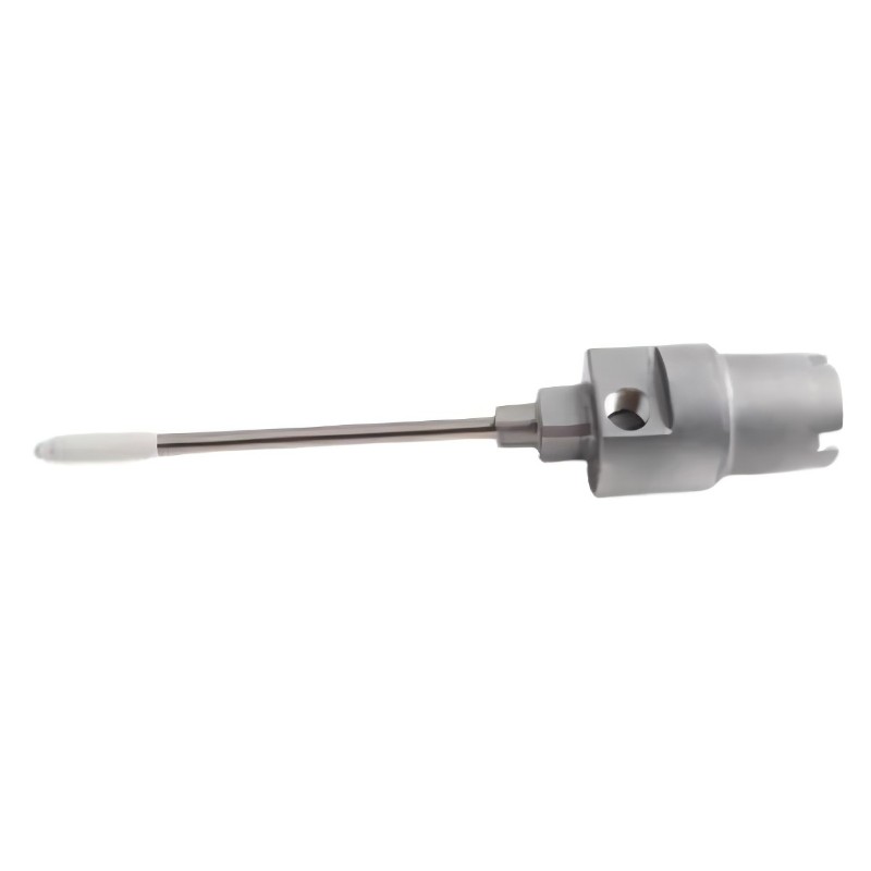
Bently Nevada 21000-00-00-00-078-04-02 — Product Overview, Technical Parameters, Applications, and Related Models
1. Product Identification
The model 21000-00-00-00-078-04-02 belongs to a product-numbering family associated with industrial machinery monitoring and vibration-protection installations. The model number appears to be a configuration-specific part number, so the exact hardware configuration should be confirmed against the equipment label or the original dimensional drawing before ordering or replacing it.
The information below distinguishes general product-family characteristics from details that cannot be reliably determined from the part number alone. Dimensions and weight are included in the tables as requested; values that require a specific drawing or verified product record are marked as unconfirmed rather than presented as exact specifications.
2. Detailed Technical Parameters
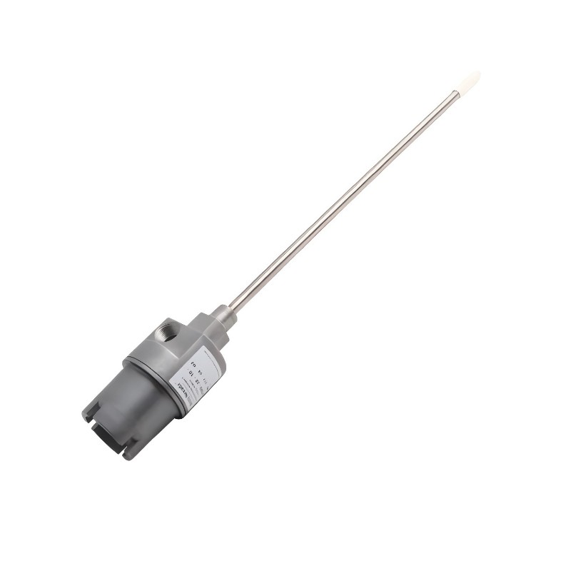
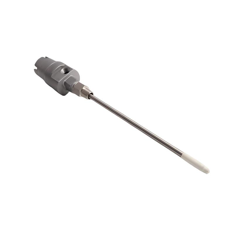
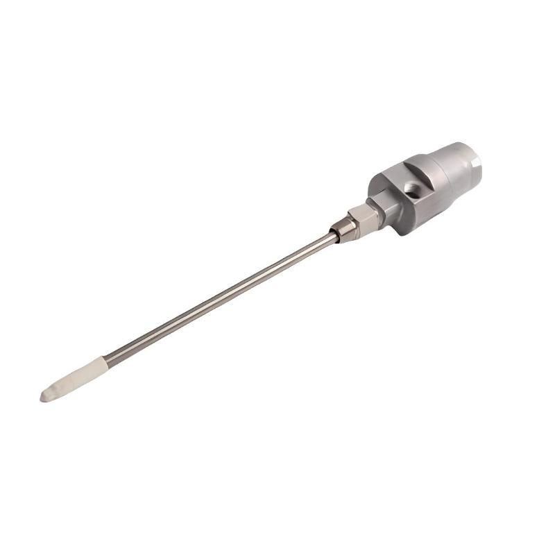
The 21000-00-00-00-078-04-02 is a proximity probe housing assembly. Its primary function is to provide a protected mounting arrangement for a proximity probe installation, helping route and protect the associated sensor hardware and conduit connections in industrial environments.
The “00” configuration fields indicate that the assembly is supplied without a probe, without a probe cable, and without a standoff adapter. The “078” field indicates a probe penetration dimension of 7.8 inches, while the “04” and “02” fields identify the fitting and mounting-thread configurations.
| Parameter | Specification |
|---|---|
| Model | 21000-00-00-00-078-04-02 |
| Brand | Bently Nevada |
| Product series | 21000 Proximity Probe Housing Assemblies |
| Product type | Proximity probe housing assembly |
| Primary function | Mechanical mounting and protection of a proximity probe installation |
| Probe option | 00 — probe not included |
| Probe cable option | 00 — probe cable not included |
| Standoff adapter option | 00 — no standoff adapter included |
| Probe penetration option | 078 — 7.8 in (198.12 mm) |
| Fitting option | 04 — one 3/4-14 NPT plug only |
| Mounting-thread option | 02 — 3/4-14 NPT |
| Housing material | Aluminum body with stainless-steel sleeve is characteristic of the 21000 series; confirm the exact supplied configuration |
| Probe compatibility | Must be selected according to the required probe system, installation geometry, and associated monitoring hardware |
| Environmental purpose | Industrial protection for externally mounted probe installations |
| Hazardous-area suitability | Depends on the applicable approvals and the completed installation |
| Overall dimensions | Exact dimensions for this part number are unconfirmed; the assembled length depends on the selected configuration and installation arrangement |
| Reference shipping/package dimensions | Not confirmed for this exact model |
| Weight (kg) | Exact model-specific net weight is unconfirmed; approximately 1.1 kg is a typical reference for the basic 21000 housing without fittings, not a guaranteed weight for this complete configuration |
| Installation style | External mounting arrangement |
| Typical industries | Power generation, oil and gas, petrochemical processing, and general industrial machinery |
| Replacement requirements | Verify the complete part number, probe compatibility, penetration dimension, fittings, mounting thread, and clearance before replacement |
Understanding the Model Number
| Code segment | Meaning | Configuration of this model |
|---|---|---|
| 21000 | Product family | Proximity probe housing assembly |
| 00 | Probe option | Probe not included |
| 00 | Probe cable option | Probe cable not included |
| 00 | Standoff adapter option | No standoff adapter |
| 078 | Probe penetration | 7.8 in (198.12 mm) |
| 04 | Fitting option | One 3/4-14 NPT plug only |
| 02 | Mounting-thread option | 3/4-14 NPT |
The model number is important because the housing is a configured mechanical assembly rather than a complete sensing instrument. Two parts that begin with “21000” may look similar but differ in probe type, cable length, penetration, fittings, or mounting arrangement.
For procurement and maintenance purposes, the complete part number should be treated as the primary identifier. A similar-looking assembly should not be assumed to be interchangeable without checking the suffix configuration.
3. Product Introduction
3.1 Product Overview
The 21000 series is designed for installations in which a proximity probe must be mounted externally to industrial machinery or an associated structure. The housing provides a defined mechanical arrangement for positioning the probe, accommodating the required penetration, and managing the conduit connection.
In a typical machinery-monitoring installation, a proximity probe measures the position or movement of a conductive target, such as a rotating shaft. The probe forms part of a larger measurement chain that may include an extension cable, signal-conditioning hardware, and a machinery-monitoring system. The housing supports the physical installation of the probe, but it does not independently perform vibration analysis or generate a complete monitoring measurement.
The 21000-00-00-00-078-04-02 is configured without a probe, probe cable, or standoff adapter. This makes it particularly relevant when those components are specified separately for the application, or when an existing installation requires a replacement housing while retaining compatible sensing components.
The 7.8-inch penetration option is an important mechanical specification. It determines the selected penetration configuration and must be checked against the machine casing, mounting position, probe geometry, and required target clearance. It should not be interpreted as a universal measurement range for the probe itself.
3.2 Main Construction and Functional Features
Housing body
The housing provides the principal mounting structure for the probe installation. The 21000 series uses a metal construction intended for industrial environments. The housing material and any fitted sleeves or sealing components should be verified against the applicable technical drawing before installation in a corrosive or high-temperature environment.
Probe mounting arrangement
The mounting arrangement supports the installation of a compatible probe at the required location. Correct positioning is important because the probe must be aligned with its target and installed within the operating limits of the sensing system.
Penetration configuration
The “078” code represents a 7.8-inch penetration option. Selecting the correct penetration is necessary to achieve the intended installation geometry and maintain suitable mechanical clearance. An incorrect length may cause interference with the machine, prevent the required probe position from being reached, or complicate maintenance access.
Conduit fitting
The “04” fitting option specifies one 3/4-14 NPT plug only. This detail matters when coordinating the housing with conduit, cable routing, and the electrical installation. The plug arrangement should be reviewed alongside the actual site wiring and applicable hazardous-area requirements.
Mounting thread
The “02” code identifies a 3/4-14 NPT mounting-thread configuration. The mating connection must have a compatible thread type and adequate mechanical engagement. Thread compatibility should be confirmed rather than inferred solely from nominal thread size.
Component separation
Because the specified assembly does not include the probe or probe cable, the installer can select those components separately where the overall system design allows it. However, the selected probe, cable, and signal-conditioning hardware must be compatible with one another.
4. Product Applications
4.1 Rotating Machinery Monitoring
The housing may be used in installations monitoring rotating machinery such as pumps, compressors, turbines, and large electric motors.
In these applications, a proximity probe may measure shaft displacement relative to the probe mounting point. Depending on the monitoring system and probe arrangement, this measurement can contribute to the assessment of shaft vibration, relative shaft position, or axial movement.
The housing provides the mechanical support needed to maintain the intended probe installation. It does not itself measure vibration; that function belongs to the compatible sensing and monitoring equipment.
4.2 Pump Systems
Industrial pumps may operate continuously under varying loads, flow rates, temperatures, and process conditions. Where a proximity probe is used to monitor a pump shaft, the probe must be mounted securely and positioned correctly relative to the target surface.
A suitable housing assembly helps organize the mounting arrangement and protect the installation. It may be relevant to process pumps, boiler-feed pumps, circulation pumps, and other rotating equipment when the engineering design calls for an externally mounted proximity probe.
The correct penetration and mounting-thread options are particularly important where access is restricted or where the housing must fit into an existing machine interface.
4.3 Compressor Installations
Compressors may require continuous condition monitoring because shaft vibration, alignment changes, bearing behavior, and other mechanical conditions can affect reliability.
A proximity probe housing can support a probe used in such a monitoring arrangement. The selected housing must match the required probe system, mounting location, and mechanical dimensions. The suitability of the completed installation depends on the machinery design and the applicable monitoring requirements.
4.4 Turbines and Power Generation Equipment
Turbines and other power-generation machines often use dedicated instrumentation to monitor shaft behavior and mechanical condition.
Where a compatible proximity probe is part of the monitoring design, the housing provides a means of installing the probe at the designated measurement location. Correct installation helps preserve the intended probe geometry and makes it easier to maintain the assembly over the equipment’s service life.
For critical machinery, installation work should follow the equipment drawing, the monitoring system requirements, and the site’s maintenance procedures.
4.5 Industrial Equipment in Demanding Environments
Industrial installations may expose instrumentation to oil mist, dust, moisture, vibration, and mechanical handling. A purpose-designed metal housing can provide a more organized and robust mounting arrangement than an improvised bracket or unprotected installation.
Nevertheless, the presence of a housing does not automatically establish a particular ingress-protection rating or hazardous-area approval for every completed installation. The applicable ratings depend on the exact assembly, fittings, seals, and installation method.
4.6 Retrofit and Replacement Work
The product can also be relevant when maintaining an existing proximity-probe installation.
Typical reasons for replacement include damaged threads, worn or corroded housing components, changes to the mounting arrangement, or a need to restore the original mechanical configuration.
Before ordering a replacement, technicians should compare the complete part number and inspect the installed assembly. A housing with a different penetration dimension or fitting configuration may require additional mechanical work and may not be a direct replacement.
5. Product Advantages
5.1 Purpose-Designed Mechanical Protection
The housing provides a defined mounting structure for a proximity probe installation. A properly selected housing can help protect the installed components from incidental mechanical contact and support a more orderly instrumentation layout.
This is especially useful where the probe must remain in a stable position relative to a shaft or other measurement target.
5.2 Configurable Installation
The 21000 product family includes different configurations for probe selection, cable length, penetration, adapters, fittings, and mounting threads.
This configuration-based approach allows an installation to be specified according to its mechanical requirements instead of relying on a single universal assembly.
For the model discussed here, the 7.8-inch penetration and specified thread and fitting options are key characteristics to preserve during replacement.
5.3 Compatibility with a Larger Monitoring System
A housing can form part of a complete machinery-monitoring installation when paired with a compatible probe and associated electronics.
The separation between the housing and sensing components can make component selection and maintenance more flexible. However, compatibility must be checked across the entire measurement chain; the housing alone does not guarantee electrical or measurement-system compatibility.
5.4 Support for Maintenance Activities
A clearly specified housing arrangement can make inspection, replacement, and maintenance planning easier.
When the correct configuration is documented, technicians can identify the required mounting thread, penetration dimension, and fitting arrangement before beginning work. This can reduce avoidable installation delays and help prevent the selection of mechanically incompatible parts.
5.5 Metal Construction for Industrial Use
The 21000 series is associated with a metal housing construction intended for industrial instrumentation installations.
A suitable metal enclosure can offer useful mechanical strength and service durability. The actual resistance to corrosion, temperature exposure, and environmental conditions depends on the precise materials, surface condition, seals, and application.
5.6 Clear Configuration Identification
The structured part number identifies several important aspects of the assembly. This supports maintenance records, spare-parts management, and replacement planning.
The advantage is greatest when the full part number is recorded accurately and the installation drawing is kept with the equipment documentation.
5.7 Practical Use in Existing Installations
Where the required mounting geometry matches an existing installation, a configured housing may be useful for maintenance or retrofit work without redesigning the entire mounting arrangement.
This benefit should not be interpreted as universal interchangeability. Before replacement, technicians should confirm the thread, penetration, fitting, probe system, and available installation clearance.
6. Brand and Product Series
| Item | Description |
|---|---|
| Brand | Bently Nevada |
| Product series | 21000 Proximity Probe Housing Assemblies |
| Product category | Machinery-monitoring installation hardware |
| Main role | Mechanical housing and mounting support for proximity probes |
| Related sensing technology | Eddy-current proximity probe systems, where specified by the installation |
| Typical measurement applications | Shaft displacement, relative shaft vibration, and shaft-position monitoring, depending on the compatible probe and monitoring system |
| Typical equipment | Pumps, compressors, turbines, motors, and other rotating machinery |
| Model-specific configuration | Probe not included; probe cable not included; no standoff adapter; 7.8-inch penetration; one 3/4-14 NPT plug; 3/4-14 NPT mounting thread |
The 21000 series should be distinguished from electronic monitoring modules and the probes themselves. The housing is the mechanical installation component; the probe senses the target, and compatible monitoring electronics process or display the resulting signal.
7. Five Related Models in the Same Series
The following five models are examples of related 21000-series housing configurations. They are useful comparison points when reviewing penetration dimensions, probe selection, cable length, and mounting requirements.
The exact dimensions and weights of each complete assembly can vary with the configuration and included fittings. Where a model-specific value is not confirmed, it is explicitly marked as unconfirmed.
| Model | Product type / configuration | Key parameters | Dimensions | Weight (kg) |
|---|---|---|---|---|
| 21000-00-00-00-015-04-02 | Proximity probe housing assembly | No probe, no cable, no standoff adapter; 1.5-inch penetration; one 3/4-14 NPT plug; 3/4-14 NPT mounting thread | Exact assembled dimensions unconfirmed | Exact weight unconfirmed |
| 21000-00-00-00-038-04-02 | Proximity probe housing assembly | No probe, no cable, no standoff adapter; 3.8-inch penetration; fitting and mounting configuration should be verified against the complete part number | Exact assembled dimensions unconfirmed | Exact weight unconfirmed |
| 21000-00-00-00-040-03-02 | Proximity probe housing assembly | No probe, no cable, no standoff adapter; 4.0-inch penetration; fitting option 03; 3/4-14 NPT mounting thread | Exact assembled dimensions unconfirmed | Exact weight unconfirmed |
| 21000-16-05-00-078-04-02 | Housing assembly configured for a 3300 XL 8 mm probe | 3300 XL 8 mm probe option; 0.5 m cable option; no standoff adapter; 7.8-inch penetration; one 3/4-14 NPT plug; 3/4-14 NPT mounting thread | Exact assembled dimensions unconfirmed | Approx. 2 kg shipping weight reported for this configuration; net weight unconfirmed |
| 21000-28-05-00-078-04-02 | Alternative housing assembly configuration | Associated with a different probe option from the 3300 XL 8 mm configuration; 0.5 m cable option; no standoff adapter; 7.8-inch penetration; confirm all suffixes before ordering | Exact assembled dimensions unconfirmed | Exact weight unconfirmed |
Important selection note: These models are not automatically interchangeable. The most important differences are the probe option, cable option, penetration dimension, fitting arrangement, and mounting thread. A model with the same penetration dimension may still be unsuitable if its probe or fitting configuration differs from the existing installation.
8. Five Popular Related Models from the Same Brand
The models below represent commonly encountered products in the broader machinery-monitoring ecosystem. They are included as related options rather than direct replacements for the 21000 housing assembly.
A housing, probe, extension cable, signal-conditioning unit, and monitoring module have different functions. Their dimensions and weights therefore cannot be compared as though they were equivalent products.
| Model | Product category | Main function / parameters | Dimensions | Weight (kg) |
|---|---|---|---|---|
| 3300 XL 8 mm Proximity Probe | Proximity probe | Measures the relative position or movement of a suitable conductive target as part of a compatible eddy-current measurement system | Depends on probe length, thread, connector, and mounting configuration; exact model required | Exact model-specific weight unconfirmed |
| 3300 XL Extension Cable | Probe extension cable | Connects a compatible proximity probe to its matching signal-conditioning component; cable length and connector configuration must match the system | Determined by cable length and connector arrangement | Exact model-specific weight unconfirmed |
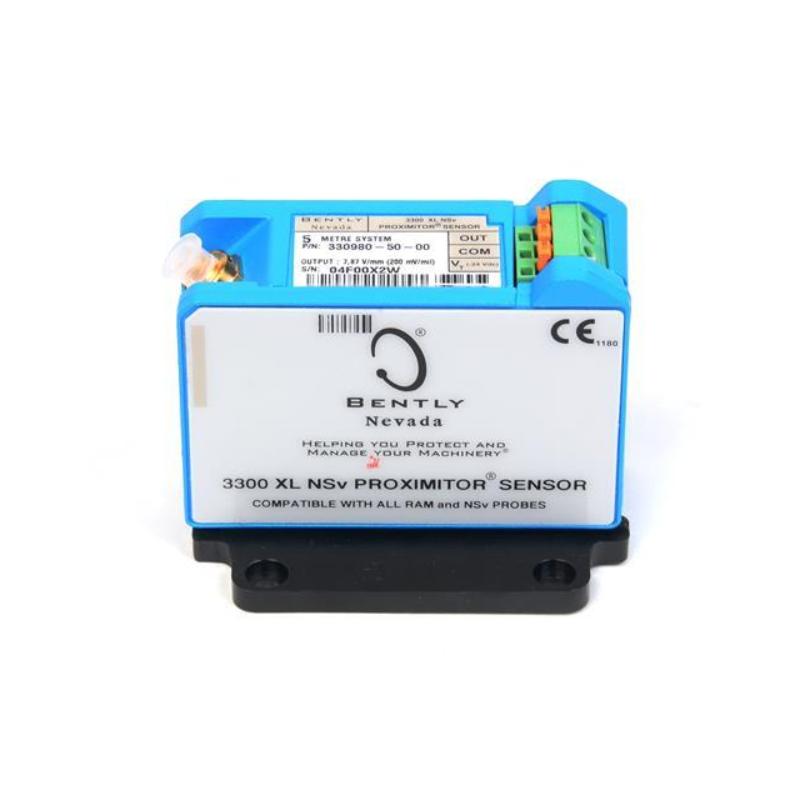
| 3300 XL Proximitor Sensor | Signal-conditioning component | Conditions the signal from a compatible probe and extension cable; system compatibility and configuration must be checked | Depends on the specific sensor housing and mounting format | Exact model-specific weight unconfirmed |
| 3500/42M Proximitor Seismic Monitor | Machinery-monitoring module | Supports monitoring functions associated with compatible proximity and seismic transducer channels, according to the installed configuration | Rack-module dimensions depend on the specified module and mounting arrangement | Exact module-specific weight unconfirmed |
| 3500/22M Transient Data Interface Module | Monitoring-system interface module | Provides an interface between compatible monitoring-system hardware and data collection or communication functions | Rack-module dimensions depend on the installed hardware configuration | Exact module-specific weight unconfirmed |
These products are useful to consider when planning a complete monitoring installation, but they should not be ordered as substitutes for the housing itself. The correct choice depends on whether the requirement is for mechanical protection, sensing, signal conditioning, or monitoring-system integration.
9. Installation and Selection Considerations
9.1 Confirm the Mechanical Dimensions
The 7.8-inch penetration option is a major selection parameter. Before installation, verify the intended probe position, casing thickness, mounting location, and clearance around the machine.
Do not assume that the penetration value is the same as the overall external length of the assembled housing. The overall dimensions depend on the actual assembly geometry.
9.2 Check Thread Compatibility
The specified mounting thread is 3/4-14 NPT. The mating part should have the correct thread form and be suitable for the intended installation.
If the assembly is being fitted into existing equipment, inspect the mating thread for damage, corrosion, or signs of previous incorrect installation. Do not force a mismatched connection.
9.3 Verify Probe and Cable Selection
This configuration does not include a probe or probe cable. Those components must be selected separately if they are required for the installation.
The selected probe and cable must be compatible with the intended signal-conditioning hardware. The appropriate probe type, cable length, connector, mounting style, and measurement range depend on the overall system design.
9.4 Review Environmental Requirements
For installations exposed to moisture, oil, dust, high temperatures, or hazardous-area conditions, verify that the complete assembly meets the requirements of the site.
The housing’s product-family characteristics should not be treated as proof that every configuration or installation has a particular protection rating or approval. Fittings, seals, conduit entries, and installation practices can affect the suitability of the completed assembly.
9.5 Maintain the Correct Probe Position
Correct probe positioning is essential to reliable measurement. The final gap, alignment, and target clearance must follow the specifications for the compatible probe system.
The housing provides mechanical support, but the sensing performance depends on the probe, target material, installation geometry, and signal-conditioning equipment.
9.6 Record the Complete Part Number
For maintenance planning, record the full model number, installation location, and relevant drawing information.
This helps prevent a partial model-number match from leading to an incorrect replacement. It is especially important when the housing is supplied without the probe or cable and those components are specified separately.
10. Procurement and Replacement Checklist
| Check item | What to verify | Why it matters |
|---|---|---|
| Complete model number | 21000-00-00-00-078-04-02 | Prevents confusion with similar configurations |
| Probe inclusion | Probe option 00 means no probe | Prevents missing components during installation |
| Cable inclusion | Cable option 00 means no probe cable | Ensures the required cable is separately accounted for |
| Standoff adapter | Option 00 means no adapter | Avoids a mismatch with the intended mounting geometry |
| Penetration | 7.8 inches (198.12 mm) | Ensures the housing fits the intended installation |
| Fitting configuration | Option 04 | Confirms the specified plug arrangement |
| Mounting thread | Option 02, 3/4-14 NPT | Ensures mechanical compatibility |
| Material and environment | Verify actual material and environmental suitability | Helps ensure the assembly suits the operating conditions |
| Dimensions | Obtain the drawing for the exact configured assembly | Prevents clearance and fitment errors |
| Weight | Confirm the net weight of the supplied configuration | Supports handling, shipping, and installation planning |
| System compatibility | Confirm probe and monitoring-system requirements | Avoids incompatibility across the measurement chain |
| Replacement suitability | Compare the existing part number and installation drawing | Reduces the risk of an incorrect replacement |
11. Summary
The Bently Nevada 21000-00-00-00-078-04-02 is a configured proximity probe housing assembly in the 21000 series. Its key identifying characteristics are the absence of a supplied probe, probe cable, and standoff adapter; a 7.8-inch penetration option; one 3/4-14 NPT plug; and a 3/4-14 NPT mounting thread.
Its principal value is mechanical: it supports the correct installation of a compatible proximity probe in an industrial machinery-monitoring arrangement. Typical applications include pump, compressor, turbine, and motor installations where proximity measurement is part of the monitoring design.
The most important points to confirm before purchasing or replacing this component are the exact penetration geometry, mounting thread, fitting configuration, compatible probe system, and dimensions shown on the applicable drawing. The overall dimensions and exact net weight for the specified configuration remain unconfirmed and should not be treated as fixed values without the corresponding product documentation.