

ProductPRODUCT
Featured products

Contact Us
- Bently Nevada
- 330102-00-12-10-01-05
- 3300 XL 8 mm Proximity Transducer System
- USA
- 8 mm
- 1.2kg
- Xiamen, China
- New & In Stock
- T/T, PayPal, Western Union
- 1 Year
- 1-3 Working Days
- DHL, UPS, TNT, FedEx and EMS.
- 24-Hour Service
- COO
- 4
Our advantage

Global Logistics
We have a 10-year logistics and express cooperation agreement, so our products can be shipped to any place in the world.

Brand new and original
Our products are imported in bulk from the place of origin. Because of the cooperative relationship, our products are all original and 100% new.

24-hour service
We provide 7*24 hours service to our customers. We will be there whenever you need us.

Price advantage
All our products are priced very favorably because we have our own warehouse and supply.
| Company Information | |||
| [email protected] | |||
| Mobile | +8615980777398 | ||
| +8615980777398 | |||
| 15980777398 |
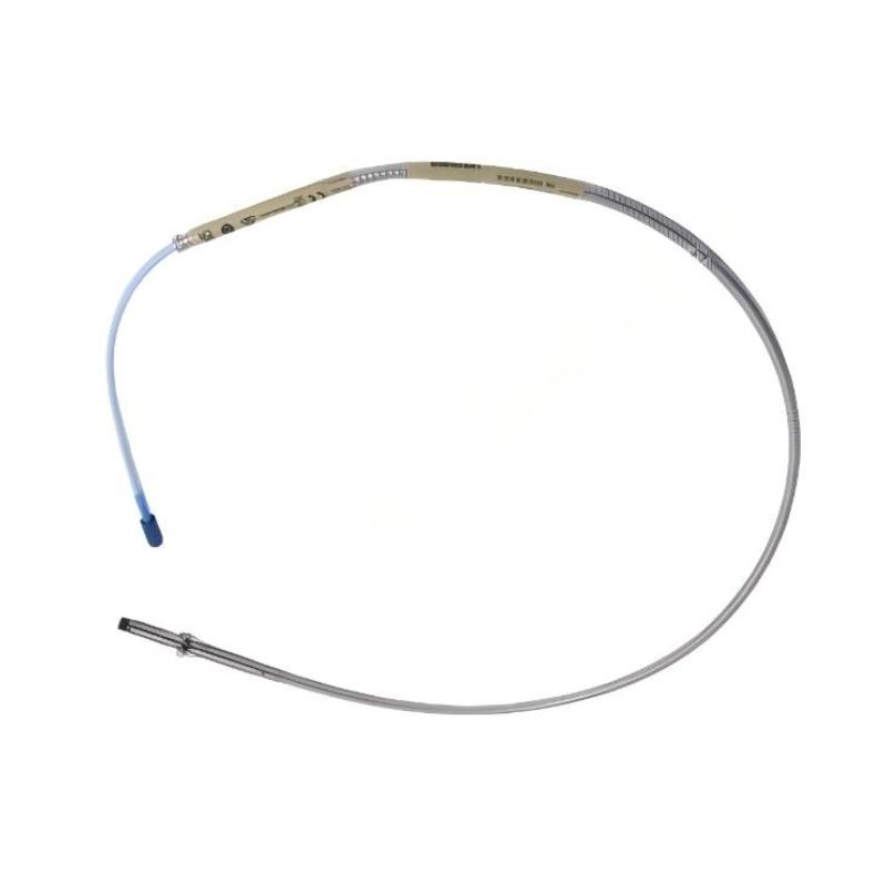
Bently Nevada 330102-00-12-10-01-05 — Technical Specifications, Product Description, Applications, and Related Models
1. Product Overview
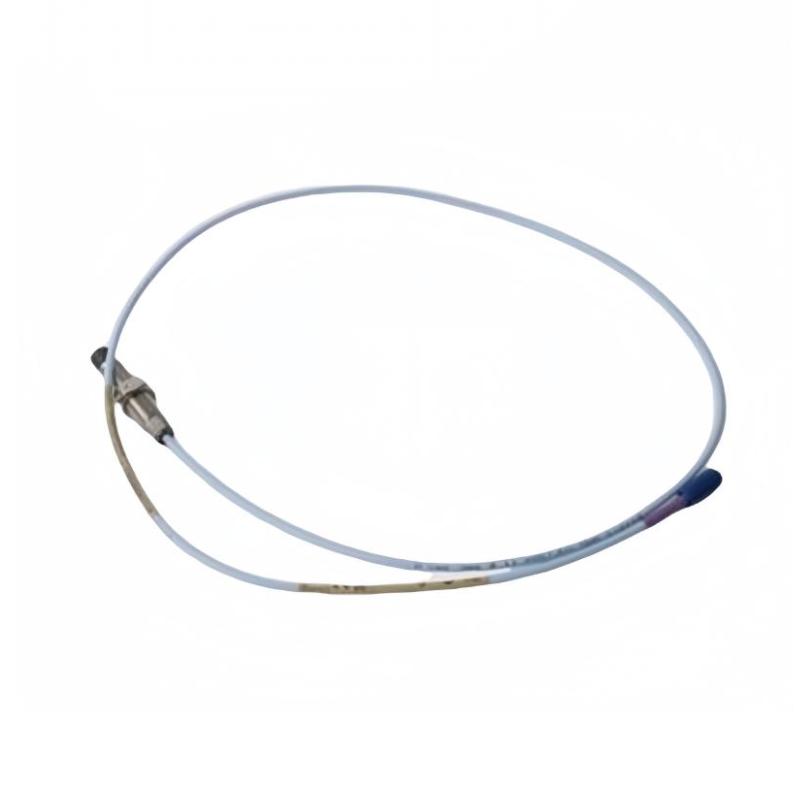
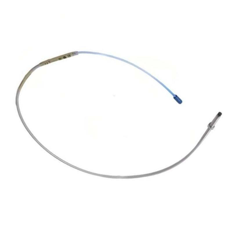
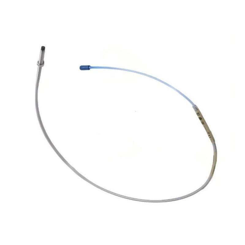
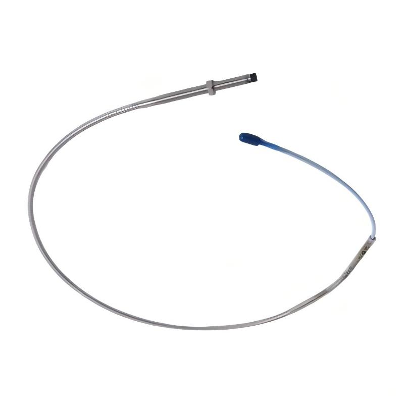
The 330102-00-12-10-01-05 is a part number in the 3300 XL proximity probe product family, used in industrial machinery monitoring applications. Proximity probes are designed to measure the position or movement of a conductive target, commonly a rotating shaft, without requiring direct mechanical contact.
A proximity probe is normally used as part of a complete measurement system that includes a compatible extension cable and signal-conditioning sensor. The probe, cable, and signal-conditioning component must be selected as a compatible combination to obtain the intended measurement performance.
The complete part number identifies a particular probe configuration. Details such as probe tip diameter, case length, cable arrangement, connector style, and thread configuration are important when selecting a replacement. The exact interpretation of every suffix in 330102-00-12-10-01-05 should be checked against the applicable part-number specification before purchasing or installing the unit.
The following overview separates general product-family characteristics from model-specific details that require confirmation. Exact dimensions and weight are included in the tables, with unconfirmed values clearly identified rather than presented as verified measurements.
2. Detailed Technical Specifications
The model 330102-00-12-10-01-05 is a 3300 XL 8 mm armored proximity probe. The 330102 model family uses an 8 mm probe tip and a 3/8-24 UNF threaded body, with an armored cable construction.
The “12” configuration corresponds to a 1.2-inch case length, and “10” indicates a nominal 1.0 m cable length. The “00” code identifies a zero unthreaded-length option. The connector and approval configuration should be confirmed against the precise ordering specification for the “01-05” suffix combination.
| Parameter | Specification |
|---|---|
| Model | 330102-00-12-10-01-05 |
| Brand | Bently Nevada |
| Product series | 3300 XL 8 mm Proximity Probe |
| Product type | Armored proximity probe |
| Measurement principle | Eddy-current, non-contact displacement measurement |
| Probe tip diameter | 8.0 mm |
| Thread size | 3/8-24 UNF-2A |
| Unthreaded length | 0 in (0 mm) |
| Case length | 1.2 in (30.48 mm) |
| Nominal cable length | 1.0 m (3.3 ft) |
| Cable protection | Armored cable construction |
| Connector | Miniature coaxial ClickLoc-type connector; exact protector configuration to be confirmed |
| Approval option | 05 — associated with CSA, ATEX, and IECEx approval options in the 3300 XL family; verify the marking on the actual unit |
| Typical linear measurement range | 2.0 mm (80 mils), with the precise usable gap determined by the compatible system and calibration |
| Typical sensitivity | 7.87 V/mm (200 mV/mil) with the specified calibration target |
| Output type | Analog voltage signal through the compatible signal-conditioning system |
| Power requirement | Passive probe element; requires a compatible Proximitor sensor to operate as a measurement system |
| Typical operating temperature | Approximately -51°C to +177°C; confirm the limits for the complete installed system |
| Typical target | Conductive metal target, calibrated according to the intended probe system |
| Probe body material | Metal threaded body; exact material grade should be confirmed from the technical specification |
| Tip material | Engineered polymer tip construction characteristic of the 3300 XL 8 mm family |
| Dimensions — case | 30.48 mm nominal case length |
| Dimensions — cable | 1,000 mm nominal cable length |
| Dimensions — overall assembly | Depends on the probe body, cable routing, connector, and protective cover; confirm from the drawing |
| Packaging dimensions | Not fixed; depend on the shipping package |
| Weight (kg) | Approximately 0.12 kg as a reference estimate for a small probe assembly; exact net weight for this part number is unconfirmed |
| Installation type | Threaded mounting |
| Typical applications | Shaft displacement, relative shaft vibration, and shaft-position monitoring |
| System requirements | Compatible probe, extension cable if required, Proximitor sensor, and monitoring equipment |
| Replacement considerations | Verify case length, thread, cable length, connector, approvals, and system compatibility |
2.1 Interpretation of the Part Number
| Code segment | Meaning | Description |
|---|---|---|
| 330102 | Probe family | 3300 XL 8 mm proximity probe with armored cable |
| 00 | Unthreaded-length option | Zero unthreaded length |
| 12 | Case-length option | 1.2-inch case length |
| 10 | Cable-length option | 1.0 m nominal cable length |
| 01 | Connector configuration | Connector option; confirm exact connector and protector arrangement against the ordering specification |
| 05 | Approval option | Associated with the family’s multi-agency approval configuration; verify the specific unit’s certification markings |
The case length and cable length refer to different parts of the assembly. The 1.2-inch case length is not the same as the total probe-and-cable length. Likewise, the 1.0 m cable length does not include the additional space required for routing the cable and fitting the connector.
When ordering a replacement, use the complete part number. A probe with the same tip diameter but a different case length, connector, cable configuration, or approval option may not be suitable for the original installation.
3. Product Introduction
3.1 General Description
The 3300 XL 8 mm proximity probe is a non-contact displacement sensor intended for machinery-monitoring applications. It detects changes in the distance between the probe tip and a conductive target, commonly a rotating shaft.
Unlike a contact sensor, the probe does not need to touch the shaft to measure its relative position. This makes it suitable for installations where the target moves continuously and where the monitoring system must track small changes in shaft position or vibration.
The model 330102-00-12-10-01-05 combines an 8 mm probe tip, a threaded mounting body, a 1.2-inch case length, a nominal 1.0 m armored cable, and a specified connector and approval configuration. These characteristics make the probe suitable for installations that require a compact threaded mounting arrangement with additional mechanical protection around the cable.
The probe is not a standalone monitoring instrument. It normally works with a compatible signal-conditioning sensor, which converts the probe’s electrical behavior into a usable signal for a monitoring system.
3.2 Operating Principle
The probe operates using eddy-current measurement technology. When the probe is supplied with the appropriate high-frequency excitation from its compatible signal-conditioning sensor, an electromagnetic field is established around the probe tip.
When a conductive target approaches or moves away from the probe, the electromagnetic coupling changes. The signal-conditioning sensor detects this change and produces an output related to the target’s position.
In a correctly configured system, this output can be used to determine relative shaft displacement. When the measurement is collected over time, the resulting signal can also be used to evaluate shaft vibration and other movement-related conditions.
The measurement performance depends on several factors, including the target material, probe gap, installation geometry, calibration, cable configuration, and signal-conditioning sensor. The probe should therefore be treated as one component of a complete measurement chain rather than as an independent vibration analyzer.
3.3 Armored Cable Construction
The 330102 family uses an armored cable arrangement. The armor helps protect the cable against incidental contact, abrasion, and mechanical handling during installation and maintenance.
This is useful in machinery enclosures where cables may pass near metal edges, structural members, or other equipment. Cable armor can improve mechanical robustness, but it does not make the cable immune to crushing, excessive bending, chemical attack, or incorrect routing.
The cable should be installed with suitable bend radii and strain relief. The connector should also be protected from impact and contamination.
3.4 Threaded Mounting Design
The probe uses a 3/8-24 UNF threaded body. This provides a defined mounting interface for a compatible threaded installation.
Correct thread engagement helps maintain the intended probe position and reduces the risk of loosening. Before installation, technicians should check the mounting thread, mounting hardware, available clearance, and required probe gap.
The probe’s case length is also important. A different case length can change how far the probe extends into the mounting point, which may affect the installation geometry or prevent the probe from reaching the intended measurement position.
3.5 Role in a Machinery-Monitoring System
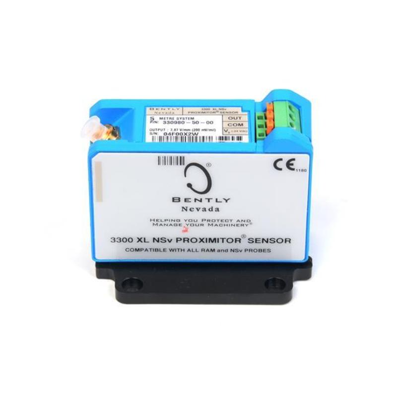
The probe is commonly used as part of a proximity transducer system consisting of:
– A proximity probe that senses the conductive target.
– A compatible extension cable, where the system configuration requires one.
– A Proximitor sensor that provides excitation and signal conditioning.
– A machinery-monitoring module or data acquisition system that receives and interprets the measurement signal.
The completed system may provide information about shaft vibration, shaft position, and other mechanical movement, depending on the installation and monitoring configuration.
The probe itself does not directly report bearing condition, predict a failure, or generate an alarm. Those functions depend on the monitoring equipment, configuration, alarm settings, and the engineering interpretation of the measured data.
4. Product Applications
4.1 Steam and Gas Turbines
Turbines operate at high speeds and may require continuous monitoring of shaft vibration and position. A compatible proximity probe can be installed near a conductive shaft target to measure relative shaft movement.
The probe’s output can help the monitoring system track changes in shaft behavior during startup, steady operation, load changes, and shutdown.
In these applications, the mounting arrangement must be designed carefully. Probe gap, target surface condition, mounting rigidity, cable routing, and system calibration all affect the quality of the measurement.
4.2 Centrifugal Compressors
Centrifugal compressors are used in many continuous-process applications. Their rotating assemblies can be sensitive to changes in operating conditions, mechanical alignment, and rotor dynamics.
A proximity probe may be used to measure relative shaft vibration or shaft position at designated monitoring locations. The signal can then be evaluated by compatible monitoring equipment.
The armored cable construction can be helpful where the cable passes through a confined machinery enclosure. Nevertheless, cable routing must still prevent rubbing, excessive bending, and interference with moving components.
4.3 Industrial Pumps
Large pumps may operate continuously and are often monitored as part of a plant reliability program.
Where the pump design uses proximity probes, the sensor may measure shaft displacement relative to the probe mounting location. The resulting measurement can support vibration monitoring and help identify changes in the machine’s operating behavior.
Not every pump uses proximity probes. The suitability of this model depends on the pump’s bearing design, shaft arrangement, monitoring strategy, and the required sensor mounting interface.
4.4 Electric Motors
Large industrial motors may use proximity probes when relative shaft displacement measurements are required.
The probe can provide a non-contact measurement of shaft movement. This may be useful for monitoring selected motor configurations, particularly where shaft movement is measured as part of a wider machinery-monitoring system.
The probe must be installed at the correct location and calibrated for the intended target. Electrical noise, mounting rigidity, shaft surface condition, and cable routing should be considered during installation.
4.5 Gearboxes and Rotating Equipment
Some gearbox and rotating-equipment installations use proximity probes to monitor shaft movement at selected locations.
The sensor can contribute to the monitoring of relative shaft vibration or position, provided that the equipment design and target geometry are suitable for this measurement method.
The 330102-00-12-10-01-05 should not be assumed to be suitable for every gearbox or rotating machine solely because it is an 8 mm probe. The mechanical dimensions and system compatibility must be checked for each application.
4.6 Bearing and Shaft Monitoring
A proximity probe may be installed near a shaft or bearing assembly to measure relative shaft motion. Depending on the measurement location and monitoring arrangement, this information may be used to track vibration patterns and changes in shaft position.
The sensor does not directly measure every aspect of bearing condition. For example, bearing temperature, lubrication condition, and some forms of bearing-surface damage require other measurement methods or additional instrumentation.
A proximity probe is most useful when it is incorporated into a monitoring plan that matches the machine’s design and operating requirements.
4.7 Condition Monitoring and Maintenance
The probe can form part of a continuous condition-monitoring system. Data from the probe may be trended over time to identify changes in shaft vibration or position.
Maintenance personnel may compare current measurements with established operating baselines and alarm thresholds. Changes can prompt further investigation, but the probe reading should be interpreted in the context of machine speed, load, process conditions, and other available measurements.
4.8 Retrofit and Replacement Installations
The model may also be considered when replacing an existing 3300 XL 8 mm proximity probe.
A replacement must match the mechanical mounting requirements and the electrical measurement system. The following characteristics are particularly important:
– Probe tip diameter and target compatibility.
– Thread type and mounting interface.
– Case length and required installation depth.
– Cable length and cable construction.
– Connector type and connector protection.
– Required certification or approval configuration.
– Compatibility with the installed Proximitor sensor and monitoring hardware.
A probe with a different suffix should not be treated as an equivalent replacement until these characteristics have been checked.
5. Product Advantages
5.1 Non-Contact Measurement
The probe measures the distance to a conductive target without physically contacting it. This makes the measurement method appropriate for rotating shafts and other targets that move continuously.
Because the probe does not need to ride against the shaft, it avoids the wear associated with a mechanical contact sensor at the measurement point.
5.2 Suitable for Small Displacement Measurements
The 3300 XL 8 mm family is designed for small displacement measurements. With the correct signal-conditioning sensor and calibration, the system can resolve changes in the target-to-probe gap that are useful for machinery monitoring.
The actual measurement performance depends on the configured system and installation conditions. A suitable probe gap and a stable mounting arrangement are essential.
5.3 Armored Cable Protection
The armored cable construction offers additional mechanical protection compared with an unarmored cable arrangement.
This can be beneficial during installation, inspection, and maintenance, especially where the cable is exposed to incidental contact with nearby structures.
Armor does not eliminate the need for careful routing. The cable should not be crushed, sharply bent, or placed where moving machinery can damage it.
5.4 Threaded Mounting
The 3/8-24 UNF threaded body provides a defined mechanical mounting interface.
When the correct mounting hardware is used, the threaded arrangement supports repeatable installation and adjustment of the probe position. This is important because the measurement depends on the distance between the probe tip and the target.
5.5 Compact Case Configuration
The 1.2-inch case-length option provides a relatively compact probe-body configuration within the 3300 XL 8 mm family.
This can be useful where mounting space is limited. However, the actual suitability depends on the available thread engagement, installation depth, required clearance, and the shape of the machine housing.
5.6 Integration with Machinery-Monitoring Systems
The probe can be integrated into a compatible proximity measurement system and used with suitable monitoring hardware.
This allows its measurements to be incorporated into a broader condition-monitoring arrangement, rather than being treated as isolated sensor readings.
The system should be configured as a complete, compatible chain. A probe that physically fits may still be unsuitable if its electrical characteristics, cable arrangement, or calibration do not match the associated electronics.
5.7 Potential Support for Early Condition Assessment
When installed in a suitable location and monitored consistently, proximity measurements can help reveal changes in shaft behavior.
Trend information may support maintenance teams in deciding when to investigate abnormal vibration or position changes. It does not guarantee that every fault will be detected, and readings should be interpreted alongside other machine data and established alarm criteria.
5.8 Configurable Product Family
The 3300 XL 8 mm family includes different probe lengths, case lengths, cable options, connector configurations, and approval options.
This makes it possible to select a probe that matches a particular mounting arrangement and measurement system.
The same configurability also means that suffixes matter. Two probes with the same family number may not be mechanically or electrically interchangeable.
6. Brand and Product Series
| Item | Description |
|---|---|
| Brand | Bently Nevada |
| Product series | 3300 XL |
| Sensor family | 3300 XL 8 mm proximity probes |
| Model | 330102-00-12-10-01-05 |
| Product category | Industrial proximity sensor |
| Measurement technology | Eddy-current displacement measurement |
| Mounting style | 3/8-24 UNF threaded body |
| Cable construction | Armored cable |
| Nominal cable length | 1.0 m |
| Case length | 1.2 in (30.48 mm) |
| Typical system role | Non-contact shaft displacement measurement |
| Associated components | Compatible extension cable, Proximitor sensor, and monitoring equipment, as required |
| Typical industries | Power generation, oil and gas, petrochemical processing, and industrial manufacturing |
| Main purpose | Support continuous monitoring of shaft position and relative shaft vibration in suitable installations |
The 3300 XL series contains both sensing components and other elements of the measurement system. A proximity probe should be distinguished from the Proximitor sensor and the monitoring module: each component performs a different function.
7. Five Related Models in the Same Series
The following models are related 3300 XL 8 mm proximity probe configurations. They can be used as comparison candidates when the required mounting depth, cable arrangement, or connector configuration differs from the original model.
The table describes representative configurations. The exact specifications of a candidate model should be confirmed before ordering, especially where the connector or approval suffix differs.
| Model | Product type | Main parameters | Dimensions | Weight (kg) |
|---|---|---|---|---|
| 330102-00-08-10-01-05 | 3300 XL 8 mm armored proximity probe | 8 mm tip; 3/8-24 UNF thread; zero unthreaded length; 0.8-inch case length; 1.0 m cable; connector and approval configuration to be verified | Case length approximately 20.32 mm; cable 1,000 mm; overall assembled dimensions depend on connector | Exact net weight unconfirmed; approximately 0.10–0.12 kg as a reference estimate |
| 330102-00-12-10-01-05 | 3300 XL 8 mm armored proximity probe | 8 mm tip; 3/8-24 UNF thread; zero unthreaded length; 1.2-inch case length; 1.0 m armored cable | Case length 30.48 mm; cable 1,000 mm; overall dimensions depend on connector and cable routing | Approximately 0.12 kg as a reference estimate; exact net weight unconfirmed |
| 330102-00-15-10-01-05 | 3300 XL 8 mm armored proximity probe | 8 mm tip; 3/8-24 UNF thread; zero unthreaded length; 1.5-inch case length; 1.0 m cable; confirm exact suffix options | Case length approximately 38.10 mm; cable 1,000 mm; assembled dimensions depend on connector | Exact net weight unconfirmed; approximately 0.12–0.15 kg as a reference estimate |
| 330102-00-20-10-01-05 | 3300 XL 8 mm armored proximity probe | 8 mm tip; 3/8-24 UNF thread; zero unthreaded length; 2.0-inch case length; 1.0 m cable; confirm connector and approval options | Case length approximately 50.80 mm; cable 1,000 mm; assembled dimensions depend on connector | Exact net weight unconfirmed; approximately 0.15 kg as a reference estimate |
| 330102-00-30-10-01-05 | 3300 XL 8 mm armored proximity probe | 8 mm tip; 3/8-24 UNF thread; zero unthreaded length; 3.0-inch case length; 1.0 m cable; confirm connector and approval options | Case length approximately 76.20 mm; cable 1,000 mm; assembled dimensions depend on connector | Exact net weight unconfirmed; approximately 0.15–0.20 kg as a reference estimate |
Selection note: The models above are examples of alternative case-length configurations, not guaranteed direct substitutes. The case length must suit the mounting geometry, while the connector and approval options must match the intended system and installation requirements. The reference weights are estimates only, not verified catalogue weights.
8. Five Other Common Models from the Same Brand
These models cover other functions in the broader machinery-monitoring product range. They are not direct replacements for the 330102-00-12-10-01-05, because they perform different sensing, signal-conditioning, or monitoring functions.
| Model | Product category | Main parameters and function | Dimensions | Weight (kg) |
|---|---|---|---|---|
| 330101-00-12-10-02-05 | 3300 XL proximity probe | 8 mm-class probe family counterpart with a non-armored cable configuration; 1.2-inch case-length option; 1.0 m cable; verify connector and approval configuration | Case length approximately 30.48 mm; cable 1,000 mm; overall dimensions depend on connector | Exact net weight unconfirmed; typically a small probe assembly |
| 330103-00-12-10-01-05 | 3300 XL proximity probe | M10 × 1 threaded probe family with armored cable; intended for installations designed around the metric mounting thread; confirm exact case and cable options | Depends on case length and cable configuration; exact dimensions unconfirmed | Exact net weight unconfirmed |
| 330104-00-12-10-01-05 | 3300 XL proximity probe | Metric-threaded armored probe family; intended for compatible installations; confirm the complete ordering configuration before selection | Depends on case length and cable configuration; exact dimensions unconfirmed | Exact net weight unconfirmed |
| 330180-90-00 | 3300 XL Proximitor sensor family | Signal-conditioning component for a compatible 3300 XL proximity probe system; exact variant and mounting configuration must be checked | Depends on the specific sensor variant and mounting arrangement | Exact model-specific weight unconfirmed |
| 3500/42M | Proximitor/seismic monitoring module | Monitoring module used for compatible proximity and seismic transducer channels in a configured machinery-monitoring rack | Rack-module dimensions depend on the specific module and rack configuration | Exact module-specific weight unconfirmed |
These models should be selected according to the function required. A different probe model may change the mounting interface, while a Proximitor sensor or monitoring module belongs to a different part of the measurement chain.
9. Installation Recommendations
9.1 Confirm the Mounting Interface
Before installing the probe, confirm that the mounting point is designed for a 3/8-24 UNF thread. Check the thread condition and make sure the probe can be installed without forcing or damaging the mounting interface.
The probe should be secured according to the applicable installation instructions. Excessive tightening can damage components, while inadequate tightening can allow the probe position to change.
9.2 Set the Correct Probe Gap
The probe must be positioned at the correct distance from the target. The required gap should be established according to the specifications for the complete transducer system.
An incorrect gap can reduce the usable measurement range or cause the signal to operate outside the intended linear region. The gap should not be set solely from a generic value without confirming the applicable sensor and target requirements.
9.3 Protect the Cable and Connector
Route the armored cable away from sharp edges, hot surfaces beyond its rating, moving machinery, and locations where it may be crushed.
The connector should be fitted and secured according to the manufacturer’s instructions. Avoid contamination of the connector interface and prevent the cable from placing excessive mechanical load on the connection.
9.4 Verify Electrical Compatibility
The probe should be connected only to a compatible signal-conditioning sensor and measurement system.
Confirm that the probe type, cable configuration, connector, and calibration match the installed electronics. A mechanically compatible probe may still produce incorrect measurements if the electrical configuration is not appropriate.
9.5 Check the Target Surface
The target should be suitable for eddy-current measurement and consistent with the system’s calibration requirements.
Target material, surface condition, geometry, and runout can influence the measured signal. For critical applications, follow the equipment-specific measurement and commissioning procedure.
9.6 Verify Environmental Approvals
If the probe is installed in a hazardous area, confirm the exact approval markings on the supplied unit and ensure that the complete installation complies with the site’s requirements.
The suffix alone should not be treated as a substitute for checking the actual certification documentation and installation conditions.
10. Maintenance and Troubleshooting
10.1 Routine Inspection
During scheduled maintenance, inspect the probe body, mounting thread, armored cable, and connector for visible damage.
Look for loose mounting hardware, damaged armor, crushed cable sections, connector contamination, or signs that the probe has shifted from its intended position.
10.2 Abnormal or Unstable Signals
If the measured signal becomes unstable, investigate the complete measurement chain rather than immediately assuming that the probe has failed.
Potential areas to check include the mounting position, cable condition, connector seating, signal-conditioning sensor, target surface, electrical interference, and monitoring-system configuration.
10.3 Incorrect Measurement Values
Unexpected displacement or vibration readings may result from an incorrect probe gap, incompatible components, an unsuitable calibration, or changes in target conditions.
Compare the installation against its original configuration and verify the sensor-system requirements before replacing components.
10.4 Replacement Planning
When a probe needs replacement, match the complete part number wherever possible. If an alternative is being considered, compare the case length, thread, cable length, connector, armor, approval configuration, and compatibility with the existing Proximitor sensor.
The same 8 mm probe tip diameter does not by itself guarantee interchangeability.
11. Procurement Checklist
| Item to verify | Requirement for this model | Reason |
|---|---|---|
| Complete model number | 330102-00-12-10-01-05 | Ensures the correct configuration is ordered |
| Probe type | 3300 XL 8 mm proximity probe | Confirms the intended sensor family |
| Thread | 3/8-24 UNF-2A | Ensures mounting compatibility |
| Unthreaded length | 0 in | Preserves the specified threaded geometry |
| Case length | 1.2 in (30.48 mm) | Ensures the probe fits the mounting arrangement |
| Cable length | 1.0 m | Confirms the required cable reach |
| Cable construction | Armored | Matches the intended cable protection |
| Connector | Confirm exact “01” connector and protector configuration | Prevents connection mismatch |
| Approval option | Confirm actual certification markings | Ensures suitability for the intended installation |
| Dimensions | Confirm the complete assembly drawing | Avoids clearance and fitment problems |
| Weight (kg) | Confirm net weight from the supplied configuration | Supports handling and shipping planning |
| Compatible electronics | Verify the associated Proximitor sensor and monitoring system | Ensures correct signal conditioning |
| Installation environment | Confirm temperature, vibration, and hazardous-area requirements | Helps ensure safe and reliable use |
12. Final Summary
The 330102-00-12-10-01-05 is a 3300 XL 8 mm armored proximity probe intended for non-contact measurement of a conductive target in industrial machinery-monitoring applications.
Its principal configuration characteristics are an 8 mm probe tip, a 3/8-24 UNF threaded body, zero unthreaded length, a 1.2-inch case length, and a nominal 1.0 m armored cable. The exact connector and approval configuration should be checked against the specific ordering specification and the markings on the supplied unit.
The probe can support shaft-position and relative shaft-vibration monitoring when installed with compatible signal-conditioning and monitoring equipment. Its usefulness depends on correct mounting, suitable target conditions, proper gap adjustment, and compatibility across the complete measurement chain.
For replacement or procurement, the most important checks are the full part number, thread, case length, cable length, connector configuration, approval requirements, and associated electronics. The exact net weight and complete assembled dimensions should be confirmed for the supplied configuration rather than inferred from approximate reference values.