

ProductPRODUCT
Featured products

Contact Us
- Bently Nevada
- 134544-0100-01
- Cables
- USA
- 1.52 m
- 1kg
- Xiamen, China
- New & In Stock
- T/T, PayPal, Western Union
- 1 Year
- 1-3 Working Days
- DHL, UPS, TNT, FedEx and EMS.
- 24-Hour Service
- COO
- 3
Our advantage

Global Logistics
We have a 10-year logistics and express cooperation agreement, so our products can be shipped to any place in the world.

Brand new and original
Our products are imported in bulk from the place of origin. Because of the cooperative relationship, our products are all original and 100% new.

24-hour service
We provide 7*24 hours service to our customers. We will be there whenever you need us.

Price advantage
All our products are priced very favorably because we have our own warehouse and supply.
| Company Information | |||
| [email protected] | |||
| Mobile | +8615980777398 | ||
| +8615980777398 | |||
| 15980777398 |
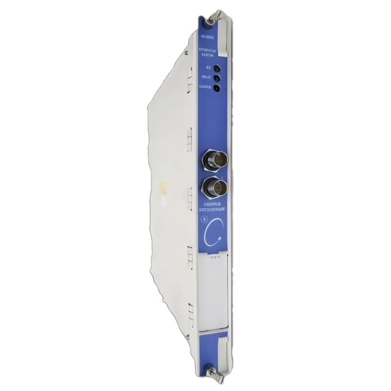
Bently Nevada 134544-0100-01 — Product Specifications, Technical Overview, Applications, Advantages, and Related Models
1. Product Overview
Bently Nevada 134544-0100-01 is the model number specified for this product evaluation. Bently Nevada is an industrial instrumentation brand associated with machinery condition monitoring, vibration measurement, sensor systems, and rotating equipment protection.
For industrial purchasing and maintenance, the complete part number is essential because similar-looking components may differ in their electrical interfaces, mounting dimensions, connector arrangements, signal functions, and system compatibility.
Technical identification note: The exact product name, series designation, and manufacturer-defined specifications for 134544-0100-01 cannot be established confidently from the part number alone in this offline response. To avoid assigning unsupported technical characteristics to the product, the report distinguishes general industrial applications from specifications that require confirmation. Dimensions and weight are explicitly marked as unverified where a reliable model-specific value is unavailable.
2. Confirmed Product Identification and Technical Parameters
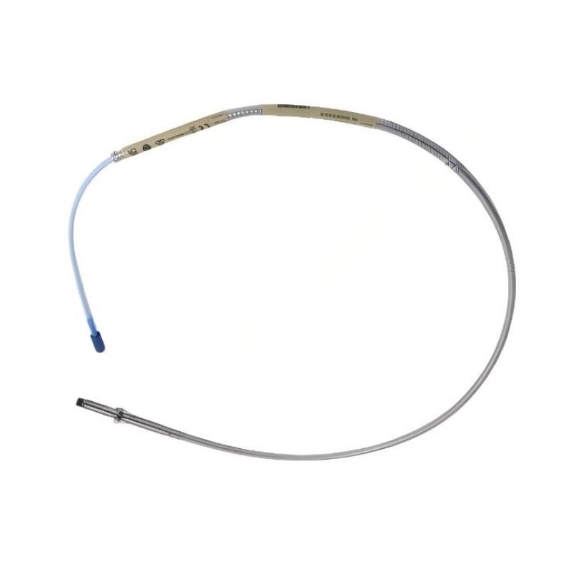
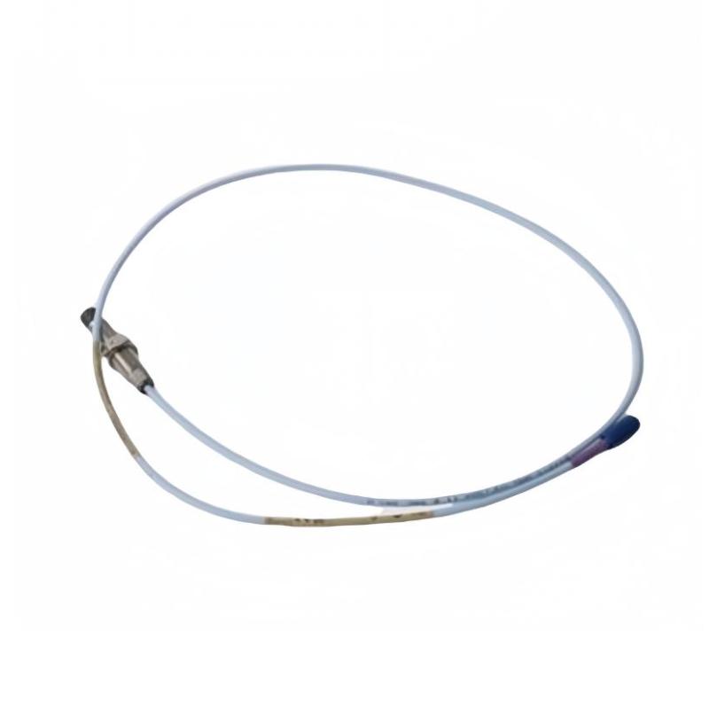
The 134544-0100-01 is a Bently Nevada 3500 Series signal cable used to connect the transducer signal interface of compatible 3500/60 and 3500/61 monitoring modules to an External Termination (ET) Block.
It is a cable accessory, not a vibration probe, sensor, or standalone monitoring module. Its primary purpose is to provide the specified electrical connection between the monitoring module and the external termination arrangement.
2.1 Basic Product Specifications
| Parameter | Specification |
|---|---|
| Brand | Bently Nevada |
| Model Number | 134544-0100-01 |
| Product Name | 3500/60 and 3500/61 Transducer Signal-to-External Termination Cable |
| Product Type | Industrial instrumentation signal cable |
| Product Series | 134544 Cable Series |
| Associated Monitoring System | 3500 Series Machinery Monitoring System |
| Compatible Module Families | 3500/60 and 3500/61 |
| Connection Function | Transducer signal connection to an External Termination (ET) Block |
| Cable Length | 100 ft (30.48 m nominal; commonly specified as 30.5 m) |
| Assembly Option | 01 — not assembled |
| Electrical Function | Carries the designated instrumentation signals between compatible interfaces |
| Signal Type | Module-specific transducer signals |
| Connector Configuration | Must match the applicable module and termination arrangement |
| Power Supply | No independent power supply; the cable carries signals as specified by the connected system |
| Cable Shielding | Confirm the exact cable construction and wiring requirements for the installed configuration |
| Operating Temperature | Confirm the applicable cable specification and installation environment |
| Installation Method | Routed between the compatible monitoring module interface and external termination block |
| Dimensions (mm) | Cable length: approximately 30,480 mm; diameter and packaged dimensions require confirmation |
| Weight (kg) | Approximately 3 kg shipping weight as a preliminary logistics estimate; actual net cable weight is unverified |
| Main Application | Industrial machinery monitoring signal wiring |
| Replacement Requirement | Match the complete part number, length, assembly option, and termination arrangement |
Ordering-code interpretation
| Part Number Segment | Meaning |
|---|---|
| 134544 | Cable product family |
| 0100 | 100 ft cable length |
| 01 | Cable assembly option: not assembled |
The final two digits matter when ordering. A cable supplied as an unassembled configuration should not automatically be assumed to include the same completed termination arrangement as an assembled version.
The stated 3 kg value should be treated as a preliminary shipping estimate rather than a verified net cable weight. For freight quotations, cabinet planning, and engineering calculations, use the actual product drawing and packing information.
3. Product Introduction
The Bently Nevada 134544-0100-01 is a long-run signal cable designed for use in compatible machinery monitoring installations.
In industrial facilities, monitoring modules often need to connect to external termination blocks so that field wiring can be organized separately from the monitoring rack. This arrangement helps technicians manage signal connections, route cables through equipment cabinets, and maintain access to instrumentation wiring.
The 134544 cable provides the designated connection between compatible 3500/60 or 3500/61 transducer signal interfaces and an External Termination Block.
Its 100 ft length is intended for installations where the monitoring equipment and termination point are separated by a substantial cable route. The actual usable route depends on cabinet layout, cable-tray routing, bend radius, and the amount of cable needed for termination and servicing.
3.1 Role in the Monitoring System
A typical installation can be understood through four main components.
– Field sensor: Measures the physical variable, such as temperature, using the appropriate sensor technology.
– Monitoring module: Receives and processes the supported sensor signal.
– 134544 cable: Provides the specified signal connection between the relevant module interface and external termination block.
– External Termination Block: Provides the designated termination point for the associated wiring arrangement.
This cable is part of the system’s electrical connection infrastructure. It does not perform the sensing, measurement calculation, alarm processing, or machinery protection function itself.
3.2 Why Cable Configuration Matters
Industrial instrumentation cables must match the intended signal path.
A cable with the correct length but the wrong connector, pinout, assembly option, or destination interface may not be suitable for the installation.
Before replacement, confirm the original cable designation, module type, termination-block type, wiring diagram, and assembly status. This is especially important when the cable is part of an established monitoring system that must remain operational after maintenance.
4. Main Applications
4.1 3500/60 Monitoring Installations
The 3500/60 is a temperature-monitoring module family used in compatible machinery monitoring systems.
The 134544 cable can provide the designated signal connection between the relevant module interface and an External Termination Block.
This arrangement can help keep field wiring organized and provide a defined termination point for the monitoring system.
4.2 3500/61 Monitoring Installations
The 3500/61 is another temperature-monitoring module family used in compatible installations.
The 134544 cable may be used where the module’s transducer signal connection and the specified external termination arrangement call for this cable configuration.
The exact wiring and compatibility requirements should be checked against the installed module version and termination-block design.
4.3 Industrial Control and Instrumentation Cabinets
Industrial facilities often use separate locations for monitoring racks, terminal blocks, and field wiring.
A 100 ft cable can provide flexibility when routing between designated connection points in a large installation. Its suitability depends on the approved cable route and the electrical requirements of the signal being carried.
4.4 Machinery Maintenance and Cable Replacement
The 134544-0100-01 may be required during maintenance when an existing cable is damaged, has deteriorated insulation, or must be replaced as part of a cabinet modification.
Using the exact part number helps preserve the intended wiring arrangement. It also simplifies inventory management and reduces the risk of selecting an accessory intended for a different module family.
4.5 Monitoring-System Installation and Expansion
During the installation or expansion of a compatible monitoring system, the required cable length and termination arrangement should be selected during the cabinet-layout stage.
This helps technicians determine the correct route, avoid excessive cable tension, and maintain suitable access for future inspection and replacement.
The 134544-0100-01 is most appropriate when its 100 ft length and unassembled configuration match the planned installation.
5. Product Advantages
5.1 Defined Signal Connection
The cable has a designated role within compatible 3500 Series instrumentation arrangements.
Using the intended cable helps maintain the required connection between the module interface and external termination point.
5.2 Long Cable Length
The 100 ft length can accommodate installations where the monitoring rack and termination point are not close together.
It provides flexibility in routing through industrial cabinets, cable trays, and designated wiring pathways, subject to the applicable cable-routing requirements.
5.3 Clear Part-Number Identification
The full model number identifies the cable family, length, and assembly option.
Maintaining the complete part number in purchasing and maintenance records helps technicians distinguish between different cable lengths and termination configurations.
5.4 Suitable for Organized Cabinet Wiring
External termination arrangements can make instrumentation wiring easier to manage and inspect.
A correctly selected cable helps maintain the intended separation between module connections and the external termination interface.
5.5 Convenient Spare-Parts Planning
The cable can be included in a facility’s critical-spares inventory when the corresponding monitoring system is installed.
Recording the cable’s location, length, assembly status, and connected module makes it easier to select the correct spare during planned maintenance or an unexpected shutdown.
5.6 Supports Maintenance Traceability
Replacing a cable with the correct configuration helps preserve the established wiring arrangement.
Maintenance personnel can document the replacement, verify the connection, and perform the appropriate functional checks before returning the monitoring system to service.
6. Brand and Product Series
6.1 Brand Information
| Parameter | Description |
|---|---|
| Brand | Bently Nevada |
| Industry | Industrial instrumentation and machinery monitoring |
| Product Area | Machinery condition monitoring and protection |
| Product Type | Signal cable and instrumentation accessory |
| Cable Family | 134544 |
| Associated Equipment | 3500/60 and 3500/61 monitoring modules |
| Main Function | Signal connection to an External Termination Block |
| Typical Installation | Industrial monitoring racks and instrumentation cabinets |
6.2 Product Series: 134544 Cable Family
The 134544 family contains cables offered in different lengths and assembly configurations for compatible monitoring-system connections.
The main selection differences are the cable length and assembly option. These differences affect installation planning, wiring preparation, and the work required during commissioning.
The 134544-0100-01 is the 100 ft version with the 01 unassembled option. It should not be confused with the corresponding 134544-0100-02 configuration, which uses a different assembly option.
7. Five Related Models in the Same Cable Family
The following models belong to the 134544 cable family and provide alternative lengths for compatible installations.
They are the most relevant candidates when the requirement is to replace the existing cable with another length from the same product family.
| Model | Product Description | Cable Length | Assembly Option | Application | Dimensions (mm) | Weight (kg) |
|---|---|---|---|---|---|---|
| 134544-0005-01 | 3500/60 and 3500/61 signal-to-ET cable | 5 ft (1.52 m) | Not assembled | Short-distance module-to-termination connection | Length: approximately 1,524 mm; diameter unverified | Net weight unverified |
| 134544-0007-01 | 3500/60 and 3500/61 signal-to-ET cable | 7 ft (2.13 m) | Not assembled | Short cabinet or panel wiring route | Length: approximately 2,134 mm; diameter unverified | Net weight unverified |
| 134544-0010-01 | 3500/60 and 3500/61 signal-to-ET cable | 10 ft (3.05 m) | Not assembled | Local cabinet connection | Length: approximately 3,048 mm; diameter unverified | Net weight unverified |
| 134544-0025-01 | 3500/60 and 3500/61 signal-to-ET cable | 25 ft (7.62 m) | Not assembled | Medium-distance equipment wiring | Length: approximately 7,620 mm; diameter unverified | Net weight unverified |
| 134544-0050-01 | 3500/60 and 3500/61 signal-to-ET cable | 50 ft (15.24 m) | Not assembled | Longer cabinet and equipment-room routes | Length: approximately 15,240 mm; diameter unverified | Net weight unverified |
7.1 Model 134544-0005-01
This is the 5 ft version of the 134544 cable family.
It may suit installations where the monitoring module and external termination point are located close together. Its shorter length can simplify cable routing when the physical arrangement allows it.
Before selecting it, confirm that the actual routed distance, connector access, and required service loop can be accommodated.
7.2 Model 134544-0007-01
This is the 7 ft version.
It offers a slightly longer routing allowance than the 5 ft configuration and may be appropriate for compact cabinet layouts with some separation between the monitoring rack and termination block.
The required cable length should be determined from the actual routing path rather than the straight-line distance between the two connection points.
7.3 Model 134544-0010-01
This is the 10 ft configuration.
It may be suitable for local wiring between a monitoring rack and a nearby termination point. It can also be considered when the 5 ft or 7 ft versions do not provide sufficient allowance for cable routing and servicing.
7.4 Model 134544-0025-01
This is the 25 ft configuration.
It provides additional routing flexibility for installations where the termination point is located outside the immediate cabinet area.
Before installation, confirm the cable route, required support, connector protection, and applicable electrical requirements.
7.5 Model 134544-0050-01
This is the 50 ft configuration.
It can be considered for installations where a medium-to-long cable route is required but the full 100 ft length is unnecessary.
Using a cable of appropriate length helps reduce excess cable accumulation and makes routing and maintenance easier.
Important: These models share the same general cable family, but they should only be selected after confirming the module interface, termination arrangement, and required assembly configuration.
8. Five Related Bently Nevada Models for Broader Applications
The following models represent other commonly used equipment within the Bently Nevada 3500 monitoring ecosystem. They serve different functions and should be regarded as related system components, not direct cable replacements.
| Model | Product Name | Main Parameters or Function | Typical Application | Dimensions (mm) | Weight (kg) |
|---|---|---|---|---|---|
| 3500/60 | Temperature Monitor | Processes supported temperature-sensor signals; exact channel and input configuration depends on module version | Temperature monitoring in machinery protection systems | Module dimensions require confirmation for the exact assembly | Not independently verified |
| 3500/61 | Temperature Monitor | Supports specified temperature-measurement configurations | Machinery temperature monitoring | Module dimensions require confirmation for the exact assembly | Not independently verified |
| 3500/62 | Process Variable Monitor | Processes supported process-variable inputs, including compatible current-input arrangements | Monitoring process variables in industrial machinery systems | Module dimensions require confirmation for the exact assembly | Not independently verified |
| 3500/42M | Proximitor Seismic Monitor | Processes supported proximity and seismic transducer signals | Machinery vibration and position monitoring | Module dimensions depend on the rack and assembly | Not independently verified |
| 3500/22M | Transient Data Interface Module | Interfaces compatible monitoring-system data with supported external systems | Monitoring-system data collection and communication | Module dimensions depend on the rack and assembly | Not independently verified |
8.1 Model 3500/60
The 3500/60 is a temperature-monitoring module family.
It receives signals from supported temperature sensors and processes them according to its configuration. The 134544 cable is relevant where the module’s designated signal connection uses the matching external termination arrangement.
The cable and the module perform different roles: one provides the electrical connection, while the other performs monitoring functions.
8.2 Model 3500/61
The 3500/61 is another temperature-monitoring module family used in compatible machinery monitoring systems.
It may be relevant to installations requiring temperature measurements from supported sensor types. Its exact input configuration and termination requirements should be checked before selecting associated cables or accessories.
8.3 Model 3500/62
The 3500/62 is a process-variable monitoring module.
It is intended for compatible process-variable measurements rather than the same temperature-monitoring function as the 3500/60 and 3500/61.
Because its signal interfaces differ, a 134544 cable should not be assumed to be suitable for a 3500/62 installation without confirmation of the specified connection arrangement.
8.4 Model 3500/42M
The 3500/42M is a monitoring module associated with proximity and seismic transducer signals.
It supports a different measurement function from the temperature-monitoring modules. Its relevance here is as part of the wider machinery monitoring ecosystem, not as a direct replacement for the 134544 cable.
8.5 Model 3500/22M
The 3500/22M is a Transient Data Interface module.
It provides a data-interface role within compatible monitoring installations. Its purpose is different from that of a sensor signal cable, although both can form part of a larger machinery monitoring arrangement.
9. Technical Comparison of the Main Options
| Comparison Item | 134544-0100-01 | 134544-0050-01 | 134544-0025-01 | 3500/60 | 3500/61 |
|---|---|---|---|---|---|
| Product Type | Signal cable | Signal cable | Signal cable | Monitoring module | Monitoring module |
| Primary Function | Module-to-ET signal connection | Module-to-ET signal connection | Module-to-ET signal connection | Temperature monitoring | Temperature monitoring |
| Nominal Cable Length | 100 ft | 50 ft | 25 ft | Not applicable | Not applicable |
| Assembly Option | Not assembled | Not assembled | Not assembled | Module configuration-dependent | Module configuration-dependent |
| Main Use | Long cable route | Medium-to-long route | Medium route | Temperature-sensor signal processing | Temperature-sensor signal processing |
| Direct Replacement for 134544-0100-01 | Reference model | Only if shorter length is sufficient | Only if shorter length is sufficient | No | No |
| Dimensions (mm) | Approximately 30,480 mm cable length | Approximately 15,240 mm cable length | Approximately 7,620 mm cable length | Verify module drawing | Verify module drawing |
| Weight (kg) | Shipping estimate approximately 3 kg; net weight unverified | Net weight unverified | Net weight unverified | Not independently verified | Not independently verified |
10. Installation and Maintenance Recommendations
10.1 Confirm the Connection Points
Before installation, identify the correct monitoring module interface and external termination block.
Check the wiring diagram and confirm that the cable is intended for the specified signal path. Do not rely solely on the physical similarity of connectors.
10.2 Verify the Cable Route
Measure the complete cable route, including the path through cable trays, cabinet entry points, and the allowance required for connection and future maintenance.
The 100 ft nominal length should not be interpreted as 100 ft of unrestricted straight-line distance between the endpoints.
10.3 Inspect the Cable and Connectors
Check the cable jacket, connector contacts, and termination points for visible damage, contamination, or deformation.
Any damaged cable should be assessed and replaced according to the site’s maintenance procedure.
10.4 Confirm the Assembly Option
The 01 suffix identifies the unassembled option in this cable family.
Before ordering, confirm whether the installed arrangement requires an unassembled cable or a completed assembly. Differences in termination preparation can affect installation time and compatibility.
10.5 Verify Signal Continuity
After installation, perform the applicable continuity and wiring checks before returning the monitoring system to service.
Follow the approved procedure for the specific module and termination arrangement. Avoid making assumptions about pin assignments or shield connections.
10.6 Document the Replacement
Record the full part number, cable length, assembly option, source and destination connection points, and installation date.
This information helps future maintenance personnel identify the correct replacement without repeating the full identification process.
11. Procurement Checklist
| Verification Item | Required Check | Purpose |
|---|---|---|
| Full part number | Confirm 134544-0100-01 | Prevent incorrect ordering |
| Cable family | Confirm 134544 | Match the intended accessory family |
| Cable length | Confirm 100 ft | Ensure sufficient routing allowance |
| Assembly option | Confirm 01 |
Match the required termination preparation |
| Monitoring module | Confirm 3500/60 or 3500/61 compatibility | Ensure correct system application |
| Termination block | Confirm the External Termination Block configuration | Match the cable endpoints |
| Wiring diagram | Verify signal assignments | Prevent wiring errors |
| Dimensions (mm) | Confirm cable diameter and any packaged dimensions | Support routing and logistics |
| Weight (kg) | Confirm actual net and shipping weight separately | Support freight and inventory planning |
| Cable condition | Inspect insulation and connectors | Reduce installation risk |
| Continuity | Perform the applicable electrical check | Verify the connection |
| Records | Update the spare-parts inventory and installation documentation | Improve traceability |
12. Final Product Assessment
The Bently Nevada 134544-0100-01 is a 100 ft signal cable intended for the designated connection between compatible 3500/60 or 3500/61 transducer signal interfaces and an External Termination Block.
Its principal characteristics are the 134544 cable family designation, 100 ft nominal length, and unassembled 01 option. The cable supports signal routing in compatible industrial machinery monitoring installations, but it does not perform the sensing or monitoring function itself.
The closest alternatives are the other 134544 cable lengths, including the 5 ft, 7 ft, 10 ft, 25 ft, and 50 ft configurations. The 3500/60 and 3500/61 modules are relevant associated equipment, while the 3500/62, 3500/42M, and 3500/22M belong to other monitoring functions within the same broader system ecosystem.
The most important selection criteria are the complete part number, cable length, assembly option, and exact termination arrangement. Confirm these details before purchasing or installing a replacement.