

ProductPRODUCT
Featured products




Contact Us
- GE
- TB63600BJ14
- Molded Case Circuit Breaker
- USA
- 555.6 × 209.6 × 149.2 mm
- 24.95 kg
- Xiamen, China
- New & In Stock
- T/T, PayPal, Western Union
- 1 Year
- 1-3 Working Days
- DHL, UPS, TNT, FedEx and EMS.
- 24-Hour Service
- COO
- 8
Our advantage

Global Logistics
We have a 10-year logistics and express cooperation agreement, so our products can be shipped to any place in the world.

Brand new and original
Our products are imported in bulk from the place of origin. Because of the cooperative relationship, our products are all original and 100% new.

24-hour service
We provide 7*24 hours service to our customers. We will be there whenever you need us.

Price advantage
All our products are priced very favorably because we have our own warehouse and supply.
| Company Information | |||
| [email protected] | |||
| Mobile | +8615980777398 | ||
| +8615980777398 | |||
| 15980777398 |
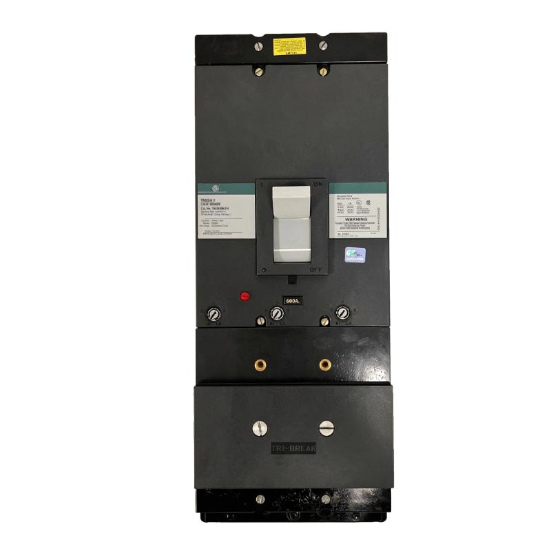
Product Overview
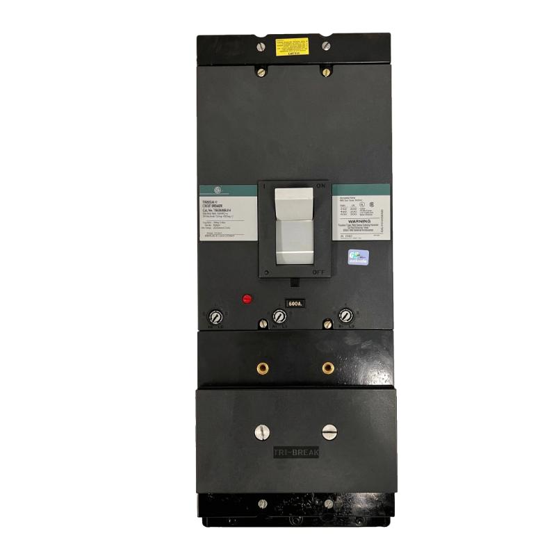
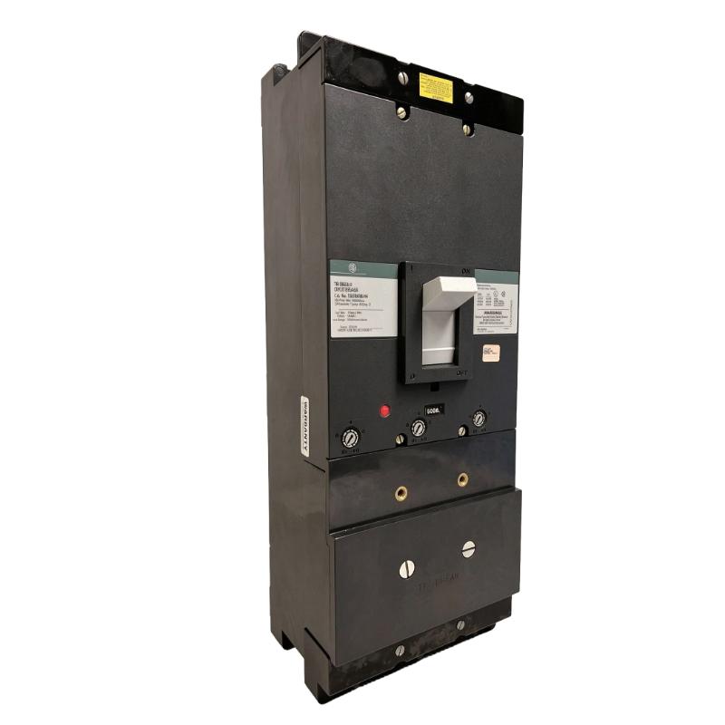
The GE TB63600BJ14 Molded Case Circuit Breaker belongs to the GE Tri-Break TB6 series and is intended for high-current power distribution applications. With a 600 A ampere rating, a three-pole configuration, and a 600 V voltage rating listed for this model, it is suited to installations where a substantial feeder or distribution circuit requires overcurrent protection.
This breaker is relevant to industrial switchgear, large distribution panels, and power systems supplying heavy electrical loads. If a short circuit or other sufficiently high-current fault occurs, the breaker’s protective mechanism interrupts the affected circuit to limit damage to conductors and connected equipment. The actual protection response depends on the installed trip unit, its settings, and the fault current available at the installation.
The TB63600BJ14 uses an interchangeable-trip arrangement within the TB6, 600 A frame family. This is useful when maintaining an established switchgear assembly because the breaker frame and its compatible trip components can be evaluated separately during replacement planning. However, interchangeability does not mean every trip unit or accessory is suitable for every breaker configuration.
The BJ14 model is listed as a three-pole Tri-Break unit with current limiters. Installation planning should account for the breaker’s mounting arrangement, terminal and lug requirements, available fault current, and coordination with upstream and downstream protective devices. A replacement should match the existing electrical ratings and approved switchgear configuration rather than relying on frame size alone.
Technical Specifications
| Parameter | Specification |
|---|---|
| Manufacturer | GE |
| Product Family | Tri-Break TB6 |
| Model | TB63600BJ14 |
| Product Type | Molded Case Circuit Breaker |
| Frame Rating | 600 A |
| Ampere Rating | 600 A |
| Number of Poles | 3 |
| Voltage Rating | 600 V |
| Trip Arrangement | Interchangeable-trip design |
| Instantaneous Trip Range | 1,200–3,500 A, as listed for the TB6 interchangeable-trip family |
| Current Limiting | Tri-Break configuration with current limiters |
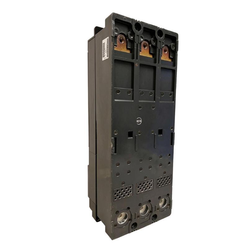
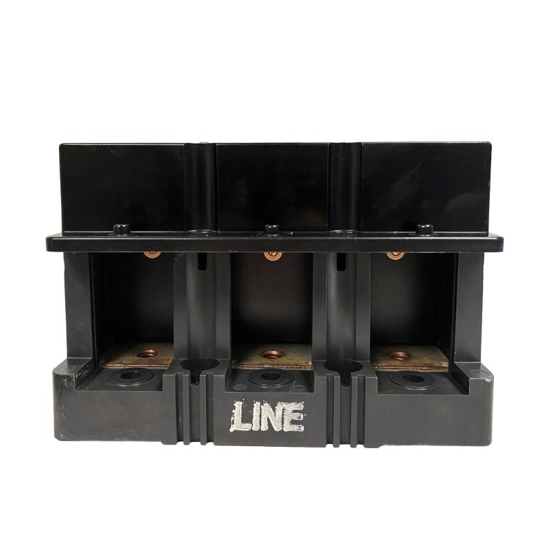
| Line/Load Lugs | Verify the required lug arrangement; catalog listing identifies the breaker without line or load lugs |
| Size | 555.6 × 209.6 × 149.2 mm |
| Weight | 24.95 kg |
Product Features
- 600 A current rating: Intended for high-current distribution circuits within the applicable system ratings.
- Three-pole construction: Provides simultaneous switching and protection of three phases.
- Tri-Break configuration: Uses the TB6 Tri-Break design with current-limiting components.
- Interchangeable-trip arrangement: Allows compatible trip components to be selected for the required ampere rating.
- High-current circuit protection: Helps disconnect circuits during qualifying overload and short-circuit conditions.
- Switchgear integration: Suitable for compatible distribution equipment designed around the TB6 breaker frame.
- Serviceable protection assembly: The breaker and its compatible trip components can be assessed separately during maintenance.
- Coordination with upstream protection: Can be incorporated into a protection scheme after checking trip characteristics and available fault current.
Working Principle
The TB63600BJ14 carries current through its main contacts during normal operation. Its protective assembly responds when current conditions exceed the limits established by the applicable trip arrangement. When a qualifying fault occurs, the breaker opens its contacts and interrupts the current flowing through the protected circuit.
A typical installation follows this sequence:
Incoming Supply → TB63600BJ14 → Protected Feeder → Industrial Load
During normal operation, the breaker remains closed and carries the load current. If a fault causes the current to rise beyond the protection system’s operating threshold, the trip mechanism initiates opening. The resulting interruption isolates the affected circuit from the supply.
The Tri-Break configuration incorporates current-limiting components. During a high-current fault, these components work with the breaker’s interruption mechanism to limit the fault current passing through the protected circuit. The effectiveness of current limitation depends on the applicable breaker configuration and the prospective short-circuit current.
The interchangeable-trip design also makes trip-unit selection an important part of the installation. The selected component must match the breaker frame and the required protection characteristics. Engineers should not assume that a trip unit intended for a different ampere rating will provide the correct protection simply because it fits the same general family.
For example, when protecting a large industrial feeder, the breaker rating must be coordinated with conductor ampacity, connected load, and the upstream protective device. The available fault current must also remain within the interrupting capability of the approved breaker configuration. These checks are essential before commissioning or replacing the breaker.
Role in an Electrical Distribution Architecture
The TB63600BJ14 forms part of the power-distribution and circuit-protection layer. It carries the normal load current and interrupts the protected circuit when the trip mechanism responds to a qualifying fault.
Incoming Power → Main Distribution Equipment → TB63600BJ14 → Feeder Conductors → Downstream Load
| System Element | Function |
|---|---|
| Incoming Supply | Provides power to the distribution assembly |
| Busbars or Distribution Conductors | Carry current to the breaker |
| TB63600BJ14 | Switches and protects the associated three-phase circuit |
| Trip Assembly | Initiates breaker opening under qualifying fault conditions |
| Current-Limiting Components | Limit fault-current passage as part of the Tri-Break arrangement |
| Feeder Conductors | Deliver power to the protected equipment |
| Downstream Load | Uses the supplied electrical power |
| Upstream Protective Device | Coordinates with the breaker to provide selective fault protection |
| Grounding and Bonding System | Supports the electrical installation’s fault-current path and safety requirements |
| Switchgear Enclosure | Houses the breaker and its associated power connections |
The complete protection arrangement must be evaluated using the applicable trip characteristics, conductor ratings, and prospective fault current. Correct breaker selection alone does not establish that the overall distribution system is properly coordinated.
Industrial Applications
| Application | Typical Use |
|---|---|
| Industrial Distribution Panels | Protecting high-current three-phase feeders |
| Manufacturing Facilities | Supplying and protecting large production loads |
| Main Electrical Switchgear | Providing circuit protection within compatible TB6 assemblies |
| Industrial Power Distribution | Isolating downstream circuits during qualifying faults |
| Large Motor Feeders | Protecting compatible feeder circuits supplying motor equipment |
| Commercial and Industrial Buildings | Distributing power to high-current electrical loads |
| Utility and Auxiliary Distribution | Protecting suitable auxiliary power circuits |
| Switchgear Maintenance | Replacing a matching TB6 breaker after verifying ratings and mounting |
| Electrical Retrofit Projects | Maintaining an existing distribution assembly built around the TB6 frame |
The TB63600BJ14 should be selected only after confirming the required voltage rating, short-circuit duty, trip characteristics, terminal arrangement, and switchgear compatibility. Applications requiring different pole counts, specialized ground-fault protection, or alternative trip characteristics may require a different breaker configuration.
Installation and Maintenance
- Verify the complete model number: Confirm TB63600BJ14 and check the breaker identification against the switchgear drawings.
- Confirm the electrical ratings: Verify the circuit voltage, continuous load current, number of poles, and applicable system requirements.
- Check the available fault current: Ensure that the approved breaker configuration is suitable for the prospective short-circuit current at the installation point.
- Inspect the trip arrangement: Confirm that the installed trip components match the required ampere rating and protection characteristics.
- Verify the lug configuration: Check the line-side and load-side terminal requirements and confirm that the correct compatible lugs are provided.
- Isolate the equipment: De-energize the relevant circuit and follow approved lockout/tagout procedures before installation or maintenance.
- Inspect the mounting assembly: Check the breaker mounting points, bus connections, and enclosure arrangement for compatibility and damage.
- Check conductor connections: Verify conductor material, wire size, terminal compatibility, and connection preparation against the applicable installation requirements.
- Tighten electrical connections correctly: Apply the specified torque for the actual terminal and lug assembly rather than using a generic value.
- Inspect the operating mechanism: Check the handle, contact mechanism, and mechanical operation according to the approved maintenance procedure.
- Test the protection scheme: Verify the breaker and associated trip components using suitable procedures and test equipment before returning the circuit to service.
- Record maintenance results: Document the model, trip-component identification, inspection findings, test results, and any replaced parts.
A molded case circuit breaker should never be serviced while energized unless a specific approved procedure permits the work. Before re-energizing, confirm that the breaker is correctly installed, all connections are secured, the enclosure is complete, and the protection scheme has passed the required checks.
Compatible System Components
The TB63600BJ14 is part of a larger distribution assembly. The surrounding components must be selected to match the TB6 frame, current rating, terminal requirements, and protection design.
| Component | Function |
|---|---|
| Compatible TB6 Trip Unit | Establishes the required trip characteristics for the breaker |
| Tri-Break Current Limiters | Form part of the current-limiting configuration |
| Compatible Line and Load Lugs | Provide the required conductor terminations |
| Distribution Busbars | Supply current to the breaker |
| Feeder Conductors | Carry power from the breaker to downstream equipment |
| Upstream Circuit Breaker | Provides coordinated protection for the upstream circuit |
| Downstream Protective Devices | Protect individual branch circuits and loads |
| Switchgear Mounting Assembly | Secures the breaker within the compatible enclosure |
| Grounding and Bonding Conductors | Support the installation’s electrical safety arrangement |
| Protection Test Equipment | Supports inspection and verification of the protection assembly |
Recommended Related Models
The following GE TB6 models share the same general 600 A frame family or are related trip components. Selection must be based on the required ampere rating and the exact switchgear configuration.
| Model | Product Type | Relevance |
|---|---|---|
| GE TB63300BJ14 | Tri-Break Molded Case Circuit Breaker | 300 A version in the TB6 family |
| GE TB63350BJ14 | Tri-Break Molded Case Circuit Breaker | 350 A version in the TB6 family |
| GE TB63400BJ14 | Tri-Break Molded Case Circuit Breaker | 400 A version in the TB6 family |
| GE TB63500BJ14 | Tri-Break Molded Case Circuit Breaker | 500 A version in the TB6 family |
| GE TB63T600 | TB6 Interchangeable Trip Unit | Related 600 A trip component |
| GE TB6BJ09 | Current Limiter | Related current-limiting component listed for compatible TB6 applications |
Key Advantages
- 600 A rating for high-current distribution circuits.
- Three-pole protection for compatible three-phase systems.
- Tri-Break current-limiting configuration.
- Interchangeable-trip arrangement within the TB6 family.
- Suitable for integration into compatible industrial switchgear.
- Supports coordinated feeder protection when correctly selected and configured.
Technical FAQs
What does the TB63600BJ14 model designation indicate?
The model belongs to the GE Tri-Break TB6 family and is listed as a three-pole, 600 A breaker with an interchangeable-trip arrangement and current-limiting components. The complete catalog configuration should be checked before selecting replacement trip components or accessories.
Does the TB63600BJ14 include line and load lugs?
The catalog listing identifies this breaker configuration as supplied without line or load lugs. The required terminal assemblies must therefore be checked against the switchgear design and conductor requirements before installation.
Why must the trip unit be verified when replacing this breaker?
The TB6 family uses interchangeable trip components, and the selected trip unit determines important protection characteristics. A replacement must match the required ampere rating, breaker frame, and protection design to avoid incorrect operation or inadequate circuit protection.
Can the TB63600BJ14 be installed wherever a 600 A breaker is required?
No. A matching ampere rating is not sufficient by itself. The breaker must also match the system voltage, pole count, prospective fault current, mounting arrangement, terminal configuration, and required protection characteristics.