

ProductPRODUCT
Featured products
Contact Us
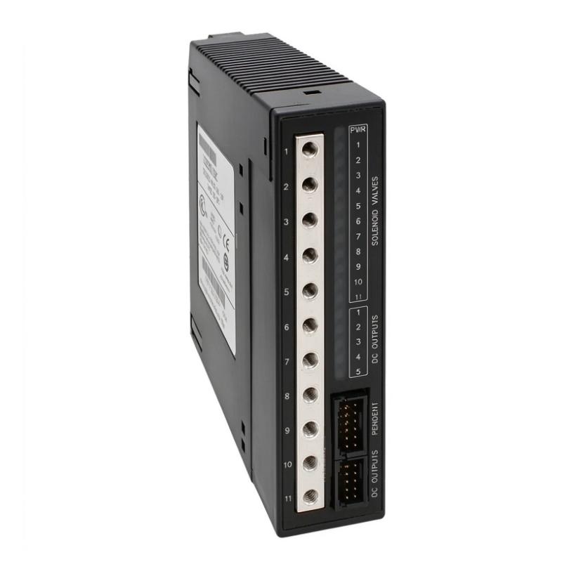
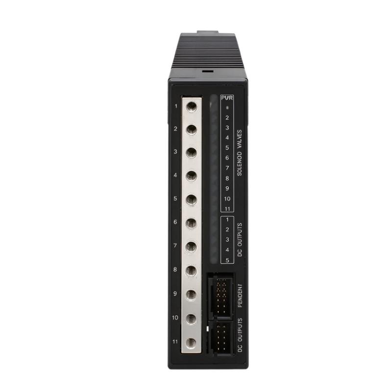
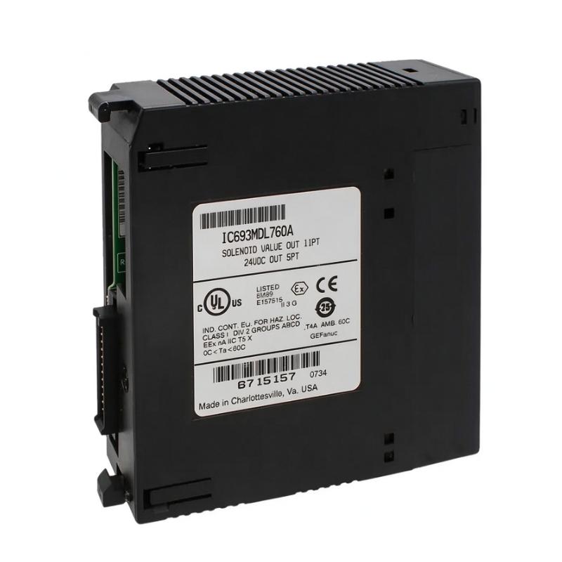
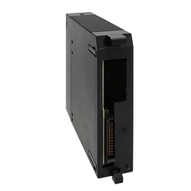
- GE
- IC693MDL760A
- Solenoid Valve Output Module
- USA
- 156 x 30 x 120 mm
- 0.172 kg
- Xiamen, China
- New & In Stock
- T/T, PayPal, Western Union
- 1 Year
- 1-3 Working Days
- DHL, UPS, TNT, FedEx and EMS.
- 24-Hour Service
- COO
- 6
Our advantage

Global Logistics
We have a 10-year logistics and express cooperation agreement, so our products can be shipped to any place in the world.

Brand new and original
Our products are imported in bulk from the place of origin. Because of the cooperative relationship, our products are all original and 100% new.

24-hour service
We provide 7*24 hours service to our customers. We will be there whenever you need us.

Price advantage
All our products are priced very favorably because we have our own warehouse and supply.
| Company Information | |||
| [email protected] | |||
| Mobile | +8615980777398 | ||
| +8615980777398 | |||
| 15980777398 |
Product Overview
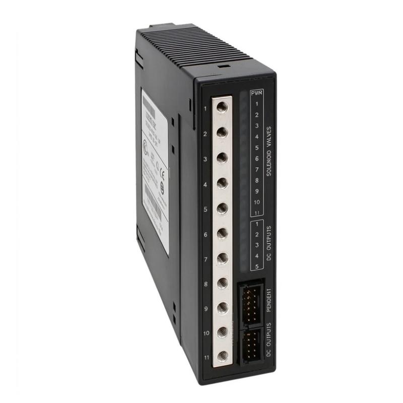
The GE IC693MDL760A Solenoid Valve Output Module is a specialized output module designed for industrial automation systems based on the GE Fanuc Series 90-30 programmable logic controller platform. It combines pneumatic valve control with discrete DC output functionality, enabling a PLC system to coordinate electrical signals and pneumatic operations within automated machinery.
Unlike a conventional digital output module that only switches electrical loads, the IC693MDL760 module family incorporates internal three-way solenoid-operated pneumatic valves. When a pneumatic output is activated, the corresponding internal valve connects the supplied compressed-air source to its output fitting. When the output is deactivated, the valve vents the output port to atmosphere.
The module family provides 11 pneumatic outputs and five 24 V DC sourcing outputs. This combination can simplify control arrangements in applications where pneumatic actuators and electrically operated devices must respond to the same PLC program. The external DC supply powers the solenoid circuits, while the PLC backplane provides the module’s internal logic power.
The IC693MDL760A is intended for applications requiring coordinated pneumatic actuation, such as automated assembly equipment, packaging machinery, material-handling systems, and industrial process-control installations. Its integrated design can reduce the need for separate electrical output hardware and individual pneumatic valve assemblies in suitable applications.
When selecting this module for a replacement or maintenance project, engineers should verify the exact model suffix, rack compatibility, electrical connections, pneumatic supply requirements, and output specifications. The characteristics of the IC693MDL760 module family provide a useful technical reference, but the installed unit’s identification and revision should always be checked before installation.
Technical Specifications
| Parameter | Specification |
|---|---|
| Brand | GE / GE Fanuc |
| Product Model | IC693MDL760A |
| Product Type | Solenoid Valve Output Module |
| PLC Platform | Series 90-30 |
| Module Family | IC693MDL760 |
| Pneumatic Outputs | 11 |
| Discrete DC Outputs | 5 |
| DC Output Voltage | 24 V DC nominal |
| DC Output Logic | Positive logic, sourcing |
| DC Output Current | 0.5 A per point at 30 V DC |
| Total DC Output Current | 2.0 A maximum across five outputs |
| Pneumatic Valve Type | Internal three-way solenoid-operated valves |
| Maximum Pneumatic Supply Pressure | 100 psi |
| External Solenoid Supply | 24 V DC nominal; 21.6–26.4 V DC |
| Pneumatic Output Connection | Threaded fitting for 10-32 adapter; 1/16-inch hose barb supplied for the module family |
| Pneumatic Supply Connection | Threaded fitting for 10-32 adapter; 1/8-inch hose barb supplied for the module family |
| Maximum Pressure Drop | 25 psi at 0.25 SCFM |
| Pneumatic Response Time | 12 ms maximum ON and OFF |
| DC Output Response Time | Approximately 0.5 ms ON and OFF for the module family |
| Internal Backplane Power | 75 mA from the 5 V DC bus |
| Dimensions Provided | 156 × 30 × 120 mm |
| Weight Provided | 0.172 kg |
| Typical Application | PLC-controlled pneumatic and discrete output operations |
Note: Electrical and pneumatic characteristics are based on documentation for the IC693MDL760 module family. Confirm the exact IC693MDL760A revision and its applicable datasheet before using these values for final engineering or procurement.
Function and Working Principle
The IC693MDL760A combines PLC-controlled electrical output signals with integrated pneumatic switching. Its primary purpose is to translate programmed control decisions into physical actions performed by pneumatic devices and compatible electrical loads.
1. PLC-Controlled Pneumatic Switching
The PLC executes a control program based on input signals, operating sequences, interlocks, and process conditions. When the program commands a pneumatic output, the module activates the associated internal solenoid valve.
The internal valve changes the pneumatic connection so that the supplied compressed air can reach the corresponding output fitting. This allows the connected pneumatic circuit to perform an operation, such as moving a cylinder or actuating a pneumatic mechanism, when the downstream circuit is correctly designed.
When the output is switched off, the internal valve vents the output port to atmosphere. The resulting movement of the actuator depends on the pneumatic circuit, actuator design, spring return arrangement, and any external directional valves or flow controls.
2. Integrated Three-Way Solenoid Valves
A three-way pneumatic valve manages connections among a pressure supply, a controlled output, and an exhaust path. In the IC693MDL760 module family, each pneumatic output incorporates an internal solenoid-operated valve.
This arrangement allows multiple pneumatic functions to be controlled directly from a PLC module. It may reduce the need for a separate manifold of individual pilot valves in applications where the integrated pneumatic outputs meet the required flow, pressure, and response specifications.
The maximum supply pressure is 100 psi for the documented module family. Engineers must also consider pressure drop, tubing size, air consumption, and actuator requirements when designing the pneumatic system.
3. Five Discrete 24 V DC Outputs
In addition to the pneumatic channels, the module family provides five 24 V DC sourcing outputs. These outputs can switch compatible external electrical loads under PLC program control.
Typical applications may include small DC-operated devices, indicator circuits, or control interfaces, provided the load voltage, current, polarity, and transient characteristics remain within the specified limits.
Each output is rated at up to 0.5 A at 30 V DC, with a combined maximum current of 2.0 A across the five points. Both the per-point and total-current limits must be observed.
4. External Solenoid Power
The solenoid circuits use an external 24 V DC supply. The documented operating range is 21.6–26.4 V DC, with 24 V DC nominal.
Separating the solenoid supply from the PLC backplane logic supply helps define the electrical power arrangement for the module. During installation, engineers must verify the supply capacity, polarity, connector assignment, common references where required, and protective measures.
The external supply must support the connected solenoids under the applicable operating conditions.
5. PLC Logic and Output Coordination
The module is accessed by the PLC program as an output module. Program logic determines when individual pneumatic channels and discrete DC outputs are activated.
For example, a packaging machine may use a sensor to detect a product, activate a pneumatic stop mechanism, and switch an auxiliary electrical output during a defined sequence. Interlocks and feedback from appropriate sensors help ensure that operations occur in the correct order.
The module provides the output hardware; the PLC program, field sensors, actuators, and pneumatic circuit determine the complete machine behavior.
Role in Industrial Control Systems
The IC693MDL760A can serve as an interface between the Series 90-30 PLC and equipment that uses pneumatic actuation or discrete DC control signals.
Integration with GE Fanuc Series 90-30 PLCs
The module is designed for the Series 90-30 control platform. It operates as part of the PLC’s I/O system, allowing the controller program to manage its output points.
Before installation, verify that the CPU, baseplate, slot configuration, power supply, programming environment, and module revision are suitable for the existing system. A module with a similar appearance or function from a different PLC family should not be assumed to be a direct replacement.
Pneumatic Actuator Control
The integrated pneumatic outputs can be used to control compatible pneumatic circuits. Depending on the machine design, these circuits may operate cylinders, stops, clamps, positioning mechanisms, or other pneumatic devices.
Correct actuator sizing and pneumatic design are essential. The module’s maximum supply pressure does not by itself determine actuator force, speed, or suitability for a particular process.
Discrete Electrical Output Control
The five DC outputs allow the PLC to coordinate additional electrical devices with pneumatic actions. This can reduce the number of separate output modules required in a suitable installation.
However, the module’s output type and current limits must match the connected loads. Devices requiring higher current, different voltage levels, or specialized isolation may need an interposing relay or another suitable interface.
Machine Sequencing and Interlocking
A PLC can use the module’s outputs as part of a sequence involving sensors, timers, actuator-position feedback, and safety-related control equipment.
For example, a pneumatic clamp may be activated only after a workpiece is detected and a machine guard is confirmed in the required state. The complete safety function must be implemented with appropriately rated safety equipment and control architecture; this output module should not be treated as a standalone safety controller.
Industrial Applications
The IC693MDL760A module is relevant to industrial installations where pneumatic mechanisms and discrete electrical outputs must be coordinated by a PLC.
1. Automated Assembly Equipment
Assembly machines often use pneumatic cylinders to position components, operate clamps, or move parts between stations. The module’s integrated pneumatic outputs can support these functions when the required pressure and flow characteristics are within specification.
The additional DC outputs may be used for compatible auxiliary control devices, allowing multiple operations to be coordinated through a single PLC program.
2. Packaging Machinery
Packaging equipment may use pneumatic actuators to position products, operate stops, control guides, or assist with carton handling.
The PLC can coordinate these movements with product sensors and other machine signals. The module’s pneumatic switching and discrete outputs can support the required sequence, provided that actuator response and cycle-time requirements are satisfied.
3. Material Handling
Material-handling systems may require pneumatic stops, diverters, clamps, and positioning devices. PLC-controlled outputs can activate these mechanisms according to product detection and conveyor sequencing.
For applications with frequent switching, engineers should evaluate compressed-air consumption, valve response, actuator duty cycle, and maintenance access.
4. Industrial Process Equipment
Certain process machines use pneumatic mechanisms to open, close, position, or secure equipment. The module can provide control signals for suitable pneumatic circuits and compatible DC loads.
Where process conditions are hazardous or loss of air pressure could create a dangerous condition, the complete system must include appropriate mechanical safeguards, monitoring, and fail-safe design.
5. Testing and Inspection Stations
Automated testing stations may use pneumatic fixtures to secure components during inspection or release them after a test is complete.
The PLC can sequence fixture operation with measurement equipment and inspection logic. The module’s outputs can participate in this sequence, while sensors and interlocks provide the information needed to confirm the machine’s state.
Installation and System Integration
Correct installation is necessary to ensure reliable electrical switching, proper pneumatic operation, and compatibility with the existing Series 90-30 system.
1. Verify the Exact Model
Before installing the module, confirm that the nameplate identifies the required IC693MDL760A variant. Check the module suffix, revision, connector layout, and applicable technical documentation.
For replacement projects, compare the existing module with the replacement unit and verify that the PLC hardware and configuration support the intended installation.
2. Check the PLC Baseplate
Confirm the compatibility of the Series 90-30 baseplate, slot arrangement, power supply, and controller configuration.
Isolate power and follow the prescribed installation procedure before inserting or removing the module. Do not install or remove hardware while energized unless the applicable manufacturer documentation explicitly permits the operation.
3. Connect the Pneumatic Supply
Connect the compressed-air supply to the specified supply fitting using suitable tubing and fittings. The documented module-family maximum supply pressure is 100 psi.
Use clean, appropriately conditioned compressed air in accordance with the equipment requirements. Check tubing size, leakage, pressure stability, and the flow requirements of the connected actuators.
The pneumatic circuit must be designed so that venting an output produces the intended behavior. Do not assume that switching off an output automatically places every connected actuator in a safe position.
4. Wire the External 24 V DC Supply
Provide the required external DC supply for the solenoid circuits. Verify voltage, polarity, available current, connector assignments, and protective-device requirements before energizing the system.
The external supply must be suitable for the total expected solenoid load. Follow the module’s wiring documentation rather than relying solely on generic 24 V DC wiring practices.
5. Connect the Discrete DC Loads
Verify that each connected load is compatible with the module’s sourcing output configuration. Observe the per-point current rating of 0.5 A and the total output current limit of 2.0 A for the five DC points.
Check the load’s operating current, inrush current, inductive characteristics, and required suppression measures. Use an appropriate interface device if a load exceeds the module’s electrical limits.
6. Configure and Test the PLC Program
After the module is installed, confirm the I/O configuration and output addressing in the PLC program. Test each output individually before running the complete machine sequence.
For pneumatic channels, verify supply pressure, tubing connections, valve switching, exhaust behavior, and actuator movement. For DC outputs, confirm the correct polarity, load response, and current requirements.
Test interlocks, fault responses, and restart behavior before returning the equipment to production.
Compatible System Components
The IC693MDL760A is designed for integration into a suitable GE Fanuc Series 90-30 automation installation. The following components represent common system elements that may be used with this type of module.
| Component | Function | Compatibility Considerations |
|---|---|---|
| GE Fanuc Series 90-30 PLC CPU | Executes the control program | Confirm CPU, firmware, configuration, and I/O compatibility |
| Series 90-30 baseplate | Provides the module mounting and backplane connection | Verify the correct rack and slot arrangement |
| Compatible PLC power supply | Supplies the controller and backplane | Check system power requirements and available capacity |
| External 24 V DC power supply | Powers the solenoid circuits | Confirm the specified voltage range and current capacity |
| Pneumatic cylinders | Convert compressed air into mechanical movement | Check force, stroke, speed, and air-consumption requirements |
| Pneumatic tubing and fittings | Connect the supply and output ports to field devices | Match the documented fitting sizes and pressure rating |
| Pressure regulator and air preparation equipment | Conditions and regulates compressed air | Maintain pressure and air quality within the system requirements |
| Sensors and limit switches | Provide process and position feedback | Match the electrical interface and PLC input configuration |
| Interposing relays or interface devices | Adapt outputs to compatible loads when required | Ensure correct ratings and suitable electrical isolation |
| HMI or operator panel | Provides operator commands and status information | Integration depends on the PLC and communication architecture |
These components are examples of a complete automation system, not a list of accessories supplied with the IC693MDL760A.
Alternative Models and Replacement Considerations
When an IC693MDL760A requires replacement, the best choice depends on the existing PLC platform, pneumatic circuit, electrical loads, and control-program configuration.
| Alternative | Considerations |
|---|---|
| GE Fanuc IC693MDL760 module family | Confirm the complete catalog number and revision before using another variant |
| Compatible Series 90-30 discrete output module | May provide electrical outputs but may not include integrated pneumatic valves |
| Separate pneumatic valve manifold and electrical output module | Can provide similar overall functionality, but requires pneumatic, electrical, and control-system redesign |
| Modern PLC with separate pneumatic control hardware | May be suitable for a broader modernization project, subject to engineering and software changes |
A replacement must not be selected solely because its output count or physical dimensions appear similar.
Before approving an alternative, verify:
- PLC platform and baseplate compatibility.
- Module revision and I/O addressing.
- Number and type of pneumatic outputs.
- Number, voltage, polarity, and current rating of discrete outputs.
- External solenoid supply requirements.
- Pneumatic pressure, flow, and response requirements.
- Fitting sizes and tubing compatibility.
- PLC program changes and commissioning requirements.
- Required safety interlocks and failure behavior.
Replacing an integrated pneumatic module with a conventional electrical output module may require a separate valve manifold and additional wiring. Such a change should be treated as an engineering modification rather than a simple plug-in substitution.
Key Advantages
Integrated Pneumatic and Electrical Outputs
The module family combines 11 pneumatic outputs with five discrete 24 V DC outputs, supporting applications that require both types of control from one PLC module.
Direct Pneumatic Switching
Internal three-way solenoid valves provide controlled connections between the air supply and pneumatic output fittings, with output venting when the relevant valve is switched off.
PLC-Based Control
The module can be controlled through a Series 90-30 PLC program, allowing pneumatic and electrical operations to be coordinated with machine logic and sensor feedback.
Compact Control Arrangement
Combining pneumatic valves and DC outputs in one module may reduce the need for separate control components in suitable applications.
Defined Electrical Output Limits
The documented 0.5 A per-point rating and 2.0 A total limit for the five DC outputs help engineers evaluate load compatibility during system design.
Support for Automated Machine Sequences
The module can participate in packaging, assembly, material handling, and testing operations where pneumatic actuation is coordinated with other automation functions.
Technical FAQs
1. What is the GE IC693MDL760A?
It is a solenoid valve output module associated with the GE Fanuc Series 90-30 PLC platform. The IC693MDL760 module family combines 11 pneumatic outputs and five 24 V DC sourcing outputs.
2. How many pneumatic outputs does the module provide?
The documented IC693MDL760 module family provides 11 pneumatic outputs. Confirm the exact hardware variant and revision before using this figure for system design.
3. What is the voltage of the discrete outputs?
The five discrete outputs use a nominal 24 V DC supply and positive-logic sourcing configuration. Their documented current rating is up to 0.5 A per point at 30 V DC.
4. What is the maximum total current for the DC outputs?
The documented maximum total current is 2.0 A across the five discrete DC outputs. The individual 0.5 A per-point limit must also be respected.
5. What is the maximum pneumatic supply pressure?
The IC693MDL760 module-family documentation specifies a maximum pneumatic supply pressure of 100 psi. Confirm the applicable documentation for the installed revision and ensure that all connected pneumatic components are rated appropriately.
6. Does the module need an external 24 V DC supply?
Yes. The documented configuration uses an external 24 V DC supply for the solenoid circuits. Verify the operating voltage range, supply capacity, polarity, and wiring details before installation.
7. Can the module control pneumatic cylinders directly?
It can switch compatible pneumatic circuits, but suitability depends on the actuator, required airflow, pressure, tubing, and circuit design. The module’s output fittings and valve characteristics must match the application requirements.
8. Is the IC693MDL760A compatible with every GE PLC?
No. It is associated with the Series 90-30 platform. Compatibility with another PLC family should not be assumed, even if the other system uses similar I/O functions.
9. What should be checked when purchasing a replacement?
Verify the complete catalog number, revision, physical condition, connectors, pneumatic fittings, and electrical ratings. Also confirm the condition of the internal valves and the compatibility of the PLC baseplate and control program.
10. Why should the model suffix be verified?
Different suffixes or revisions can indicate hardware or documentation differences. Confirming the exact variant helps avoid incorrect assumptions about output characteristics, connections, and replacement compatibility.
Procurement and Maintenance Recommendations
When purchasing the GE IC693MDL760A, begin by checking the exact model designation on the existing module. Compare the replacement’s label, connectors, pneumatic fittings, and revision with the installed hardware.
For used or refurbished units, request clear photographs of the nameplate and connection points. Where possible, obtain evidence of functional testing for both pneumatic switching and the five discrete DC outputs. Confirm whether the unit includes any accessories and establish the supplier’s warranty and return conditions.
During maintenance, inspect pneumatic tubing, fittings, air supply quality, and output behavior. Look for leaks, contamination, sticking valves, and inconsistent actuator movement. Electrical checks should include the external 24 V DC supply, connectors, grounding arrangements, and load-current requirements.
Keep the PLC configuration and I/O addressing documented. After replacement, test each output individually and verify the complete operating sequence, including interlocks and fault responses.
The dimensions of 156 × 30 × 120 mm and weight of 0.172 kg are the supplied listing values. Verify the physical measurements and shipping weight before using them for panel planning or logistics.
Conclusion
The GE IC693MDL760A Solenoid Valve Output Module is designed for PLC-based automation applications that require coordinated pneumatic switching and discrete electrical outputs. The documented IC693MDL760 module family combines 11 pneumatic outputs with five 24 V DC sourcing outputs, allowing compatible pneumatic actuators and electrical loads to be controlled through a Series 90-30 PLC program.
For successful integration, engineers should verify the exact module revision, external solenoid power, pneumatic pressure and flow requirements, output-current limits, and PLC hardware compatibility. Careful installation, functional testing, and accurate replacement identification help maintain reliable operation in automated assembly, packaging, material handling, and other industrial applications.