

ProductPRODUCT
Featured products


Contact Us
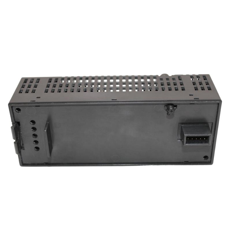
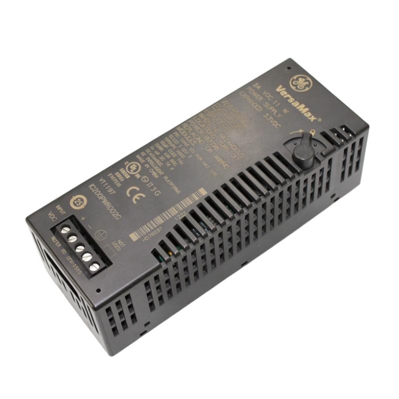
- GE
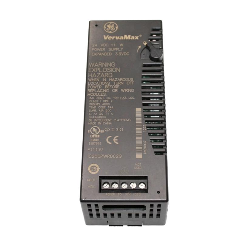
- IC200PWR002G
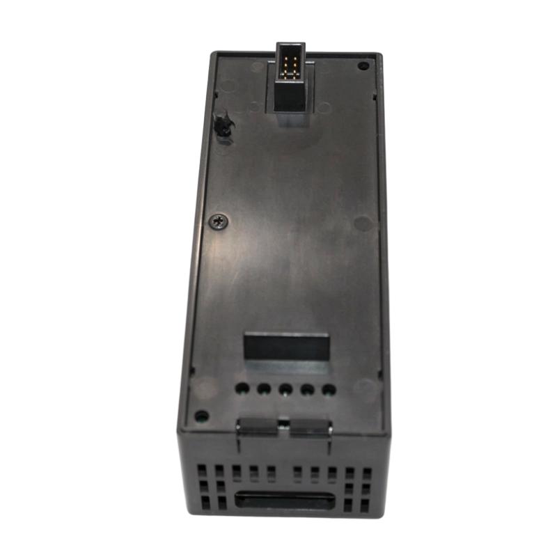
- VersaMax Power Module
- USA
- 133.4 x 39 x 49 mm
- 0.12 kg
- Xiamen, China
- New & In Stock
- T/T, PayPal, Western Union
- 1 Year
- 1-3 Working Days
- DHL, UPS, TNT, FedEx and EMS.
- 24-Hour Service
- COO
- 6
Our advantage

Global Logistics
We have a 10-year logistics and express cooperation agreement, so our products can be shipped to any place in the world.

Brand new and original
Our products are imported in bulk from the place of origin. Because of the cooperative relationship, our products are all original and 100% new.

24-hour service
We provide 7*24 hours service to our customers. We will be there whenever you need us.

Price advantage
All our products are priced very favorably because we have our own warehouse and supply.
| Company Information | |||
| [email protected] | |||
| Mobile | +8615980777398 | ||
| +8615980777398 | |||
| 15980777398 |
Product Overview
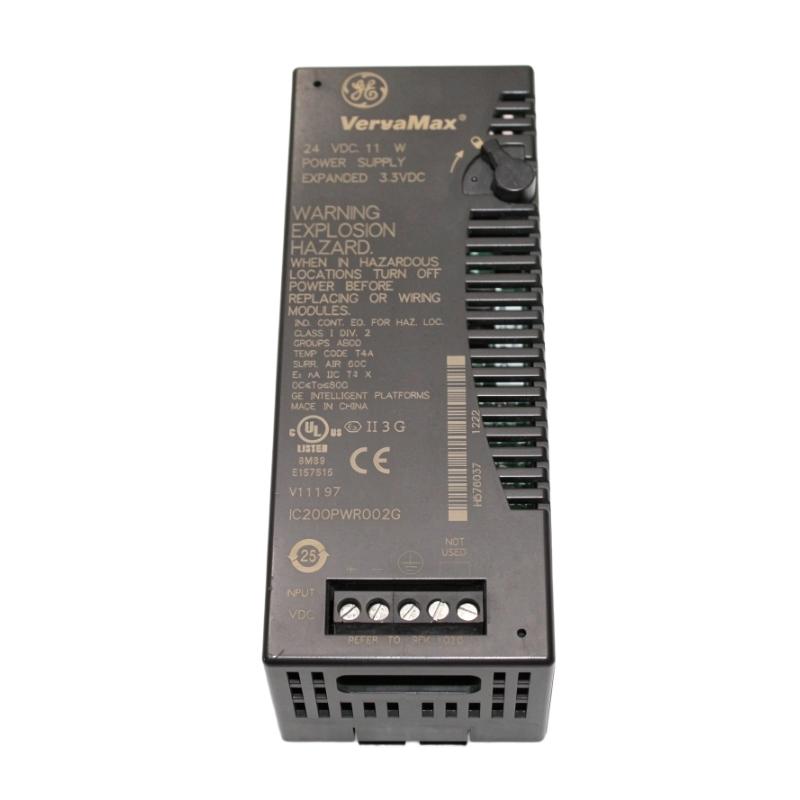
The GE IC200PWR002G VersaMax Power Module is an expanded DC power supply designed for compatible GE Fanuc VersaMax programmable logic controller (PLC) and distributed I/O systems. Originally associated with GE Intelligent Platforms, the VersaMax automation portfolio is now part of Emerson’s automation product range.
The IC200PWR002G accepts a nominal 24 V DC input and provides regulated 5 V DC and 3.3 V DC outputs for supported VersaMax system electronics. Its expanded 3.3 V output capability makes it suitable for system configurations that require more 3.3 V current than the standard IC200PWR001G power supply can provide.
This module can be installed directly on a compatible VersaMax CPU or network interface unit (NIU) to serve as the main power source for an I/O station. It can also be used with a compatible power supply booster carrier to provide supplemental power to supported modules in a larger system.
With an input voltage range of 18–30 V DC, an input power rating of 11 W, and a maximum combined output current of 1.5 A, the IC200PWR002G is intended for relatively low-power control-system electronics rather than direct operation of motors, solenoids, or other high-current field loads.
The module includes protection against short circuits, overloads, and reverse polarity. Its compact design supports installation in distributed automation cabinets where reliable power for PLC electronics and I/O assemblies is essential.
When selecting this module for maintenance or replacement, engineers should confirm the complete part number, revision, mounting arrangement, and current requirements of the connected system. A power supply with a similar appearance may have a different input voltage or output-current capability.
Technical Specifications
| Parameter | Specification |
|---|---|
| Brand | GE Fanuc / GE Intelligent Platforms |
| Current Product Portfolio | Emerson Automation |
| Model | IC200PWR002G |
| Product Series | VersaMax |
| Product Type | Expanded DC Power Supply Module |
| Nominal Input Voltage | 24 V DC |
| Input Voltage Range | 18–30 V DC |
| Input Power | 11 W |
| Output Voltages | 5 V DC and 3.3 V DC |
| Maximum Combined Output Current | 1.5 A |
| Maximum 3.3 V Output Current | 1.0 A |
| 5 V Output Current | Up to the remaining current within the 1.5 A combined limit |
| Hold-Up Time | Approximately 10 ms |
| Inrush Current | 20 A maximum for 6 ms at 24 V DC; 25 A maximum for 6 ms at 30 V DC |
| Protection | Short circuit, overload, and reverse polarity |
| Power Isolation | Non-isolated configuration |
| Mounting | Compatible VersaMax CPU, NIU, or power supply booster carrier |
| Dimensions | 133.4 × 39 × 49 mm |
| Weight | 0.12 kg |
| Typical Application | VersaMax PLC and distributed I/O power supply |
Note: The 5 V and 3.3 V outputs share a combined current limit. The total must not exceed 1.5 A. The available current on the 5 V output decreases as current demand on the 3.3 V output increases.
Function and Working Principle
The IC200PWR002G converts an external 24 V DC supply into regulated DC power rails used by compatible VersaMax automation electronics. These power rails support the internal logic and backplane requirements of the connected control system.
1. DC Power Conversion
The module receives an external DC supply within its specified input range of 18–30 V DC. Internal conversion circuitry produces the required 5 V DC and 3.3 V DC outputs.
These regulated outputs are intended for supported control-system electronics. They should not be treated as general-purpose field power supplies without confirming the electrical requirements of the connected equipment.
Stable DC power is important for PLC operation because the CPU, communication interfaces, and I/O electronics rely on suitable supply voltage to process logic and exchange signals correctly.
2. Expanded 3.3 V Output Capability
The IC200PWR002G is an expanded power supply variant. It supports up to 1.0 A on the 3.3 V output while maintaining a maximum combined output current of 1.5 A.
The 5 V output shares the remaining current capacity. For example, if a system draws 0.4 A from the 3.3 V output, the theoretical remaining current allowance for the 5 V output is 1.1 A, provided all other operating conditions remain within specification.
This shared-current arrangement must be considered during system design. Engineers should calculate the actual current demand of all connected components rather than assume that both outputs can independently deliver their maximum ratings at the same time.
3. Main Power Supply Operation
When mounted on a compatible VersaMax CPU or NIU, the IC200PWR002G can function as the main power supply for the associated I/O station.
In this configuration, the module supports the power requirements of the relevant system electronics. Correct mounting and electrical connections are necessary to ensure that the supply is recognized and operates as intended.
4. Supplemental Power Supply Operation
In a larger I/O configuration, the module may be installed on a compatible power supply booster carrier to provide supplemental power to supported modules.
This arrangement can help accommodate the power requirements of a larger assembly, subject to the system’s architecture and installation rules. It does not mean that the module can power an unlimited number of additional devices; the available current and supported configuration must be checked carefully.
5. Electrical Protection
The module incorporates short-circuit, overload, and reverse-polarity protection. These features help protect the power supply and connected electronics against certain electrical faults.
Protection functions do not replace correct wiring, appropriately rated upstream protection, or the manufacturer’s grounding requirements. A fault in the external supply or a connected module may still cause the station to lose power.
Role in Industrial Control Systems
The IC200PWR002G supports the power architecture of VersaMax PLC and distributed I/O systems. Although it does not execute control logic itself, it provides the DC power required for compatible control electronics to operate.
PLC Power Support
A PLC depends on stable power for its processor, memory, and internal communication functions. When used in an approved configuration, the IC200PWR002G supplies the required DC rails to supported VersaMax components.
An inadequate or unstable supply can lead to intermittent operation, communication interruptions, or unexpected system resets. Power-supply selection should therefore include a review of the connected hardware’s voltage and current requirements.
Distributed I/O Power
Industrial automation systems often distribute I/O modules across multiple locations in a control cabinet or machine. Each station must have a suitable power arrangement for its installed components.
The IC200PWR002G can support compatible VersaMax I/O assemblies when installed according to the applicable system configuration. Engineers should calculate total module consumption and verify whether the selected power supply is sufficient for the station.
Network Interface Unit Support
A VersaMax network interface unit connects supported I/O hardware to a wider control network. Depending on the configuration, the IC200PWR002G may provide the primary power supply for a compatible NIU-based station.
The correct power supply must be selected according to the NIU model, the I/O arrangement, and the applicable installation documentation. Compatibility should not be inferred from the VersaMax family name alone.
Power Distribution and System Reliability
A correctly sized power supply helps maintain the stability of the control system’s internal electronics. During troubleshooting, checking input voltage, output loading, grounding, and connections can help identify whether a power problem is contributing to PLC or I/O faults.
The IC200PWR002G is one element of the power architecture; system reliability also depends on the external 24 V DC source, wiring, grounding, environmental conditions, and the condition of connected modules.
Industrial Applications
The IC200PWR002G is intended for control-system power rather than direct high-power machinery operation. Its role is to support compatible automation electronics in industrial installations.
1. PLC Control Cabinets
In PLC cabinets, the module can supply the required DC power rails for supported VersaMax components. Stable internal power helps the PLC and its associated I/O equipment operate consistently during production.
The compact form factor is useful where cabinet space is limited, provided adequate mounting access and ventilation are maintained.
2. Distributed I/O Stations
Distributed I/O stations collect signals from field sensors and transmit output commands to compatible devices through a PLC or network interface. The IC200PWR002G can support the power requirements of an appropriately configured VersaMax station.
Before adding I/O modules, engineers should verify the total power demand and the station’s allowable configuration.
3. Manufacturing Automation
Production equipment often uses PLCs to coordinate sensors, actuators, conveyors, and machine sequences. The IC200PWR002G supports the electronics of compatible VersaMax control assemblies used within these systems.
Its contribution is indirect but important: the module supplies power for control electronics rather than controlling the production process itself.
4. Material-Handling Equipment
Conveyors, sorting machines, and packaging lines may use distributed I/O to monitor photoelectric sensors, limit switches, and actuator states. A suitable VersaMax power arrangement helps maintain reliable signal processing and control.
The power supply’s 1.5 A combined output limit must be respected, and field-device power should be supplied separately where the design requires it.
5. Process Monitoring and Utility Systems
Water treatment equipment, utility installations, and other process-control systems may use PLC-based monitoring and control panels. In suitable VersaMax installations, the IC200PWR002G can provide internal DC power for the control electronics.
Actual suitability depends on the PLC hardware, I/O configuration, environmental conditions, and the requirements of the overall control system.
Installation and System Integration
Correct installation is essential for electrical safety and stable operation. The IC200PWR002G should be installed only in a compatible VersaMax configuration.
1. Verify the External DC Supply
The module requires a nominal 24 V DC input and supports an input range of 18–30 V DC. Confirm that the external supply remains within this range under normal operation and during expected load changes.
The external source must also be capable of handling the module’s input power demand and startup inrush current. A source that meets the nominal voltage requirement but cannot support the current demand may cause voltage dips or unreliable startup.
2. Confirm Mounting Compatibility
The IC200PWR002G is designed to mount on compatible VersaMax CPUs, NIUs, or power supply booster carriers, depending on the application.
Before installation, verify that the target component and mounting arrangement support this power supply. Do not force the module into an incompatible carrier or use an unapproved mechanical arrangement.
3. Check Output Loading
Calculate the current demand on both the 5 V and 3.3 V rails. The combined output current must not exceed 1.5 A, and the 3.3 V output must remain within its 1.0 A maximum.
When adding modules to an existing station, review the current consumption of all installed components. A station that operates correctly under light load may become unstable if additional hardware pushes the power supply beyond its limits.
4. Grounding Requirements
The module’s DC negative terminal is internally connected to frame/earth ground. A floating input supply should not be used with this configuration.
Follow the manufacturer’s grounding and wiring instructions and the applicable electrical codes. Improper grounding may cause equipment malfunction or create an electrical safety risk.
5. Polarity and Wiring Inspection
Verify input polarity before energizing the module. Inspect terminals and conductors for secure connections, damaged insulation, corrosion, and signs of overheating.
Disconnect the power source before installing, removing, or rewiring the module. Follow site lockout procedures and verify the safe condition of the circuit before handling the equipment.
6. Startup and Functional Testing
After installation, measure the input voltage and check the connected system’s operation. Confirm that the PLC, NIU, and supported I/O modules power up as expected.
If the system fails to start, check input voltage, polarity, grounding, module seating, output loading, and the condition of the external supply. Record any changes made during troubleshooting.
Compatible System Components
The IC200PWR002G is designed for use with supported VersaMax components. The following table describes typical system relationships; exact compatibility depends on the hardware revision and approved system configuration.
| Component | Function | Integration Considerations |
|---|---|---|
| VersaMax CPU | Executes PLC logic and coordinates automation | Verify the CPU’s power-supply compatibility |
| VersaMax Network Interface Unit | Connects distributed I/O to a control network | Check NIU model and installation requirements |
| VersaMax I/O modules | Receive field inputs and drive control outputs | Calculate module power consumption |
| IC200PWB001 Power Supply Booster Carrier | Supports a supplemental power supply arrangement | Confirm carrier compatibility and intended installation |
| External 24 V DC power supply | Provides the module’s input power | Must remain within 18–30 V DC and support startup demand |
| Control cabinet | Houses the automation system | Provide secure mounting and suitable environmental protection |
| Grounding system | Establishes the required electrical reference | Follow the manufacturer’s grounding requirements |
| Field sensors and actuators | Provide process signals and perform physical actions | Check whether they require separate field power |
The presence of a component in this table does not mean it is included with the IC200PWR002G. Confirm the complete bill of materials for the target installation.
Alternative Models and Replacement Considerations
When replacing the IC200PWR002G, engineers should compare the input voltage, output rails, output-current allocation, mounting arrangement, and system compatibility. A module with a similar physical size may have a different electrical specification.
| Alternative Model | Key Difference or Consideration |
|---|---|
| GE IC200PWR001G | Standard VersaMax DC power supply with lower 3.3 V output capability |
| GE IC200PWR011 | Isolated 24 V DC input power supply; verify output capability and mounting compatibility |
| GE IC200PWR012 | Isolated 24 V DC supply with expanded 3.3 V output capability; verify the complete system requirements |
| GE IC200PWR102 | VersaMax power supply with 120/240 V AC input and 5 V / 3.3 V DC outputs; not a direct electrical substitute for a 24 V DC input model |
| GE IC200PWR202 | 12 V DC input power supply configuration; unsuitable as a direct substitute without checking system requirements |
Before selecting a replacement, compare the following:
- Exact catalog number and revision.
- Input voltage range and supply type.
- 5 V and 3.3 V output requirements.
- Maximum combined output current.
- Mounting and carrier compatibility.
- Grounding and isolation characteristics.
- Current demand of the connected CPU, NIU, and I/O modules.
- Availability and lifecycle status.
The IC200PWR002G should not be replaced solely because another module is also described as a VersaMax power supply. The replacement must meet the electrical and mechanical requirements of the installed system.
Key Advantages
Expanded 3.3 V Output Capability
The module provides up to 1.0 A on its 3.3 V rail, subject to the total combined output limit. This can support compatible VersaMax configurations with higher 3.3 V power demand.
Dual DC Output Rails
The 5 V and 3.3 V outputs support the power requirements of compatible control-system electronics.
Flexible System Placement
Depending on the approved configuration, the module can act as the primary power supply on a compatible CPU or NIU, or as supplemental power on a booster carrier.
Compact Design
Its dimensions of 133.4 × 39 × 49 mm and supplied weight of 0.12 kg suit compact control cabinets and modular automation installations.
Integrated Protection Features
Short-circuit, overload, and reverse-polarity protection help protect the module under certain fault conditions.
Established VersaMax Platform Compatibility
The IC200PWR002G is designed for the VersaMax automation family, making it relevant to maintenance and spare-parts requirements for existing compatible systems.
Technical FAQs
1. What is the GE IC200PWR002G?
It is an expanded DC power supply module for compatible GE Fanuc VersaMax automation systems. It accepts 24 V DC nominal input and provides 5 V DC and 3.3 V DC outputs.
2. What is the input voltage range?
The specified input range is 18–30 V DC, with 24 V DC nominal input.
3. What is the maximum output current?
The maximum combined output current is 1.5 A. The 3.3 V output can supply up to 1.0 A, while the 5 V output receives the remaining current capacity.
4. Can the 5 V and 3.3 V outputs both operate at their maximum ratings simultaneously?
No. The two output rails share a 1.5 A combined current limit. The available current on one rail depends on the current drawn by the other.
5. Can this module power field sensors and actuators directly?
It is primarily intended to supply supported VersaMax control-system electronics. Field devices should be powered according to their own requirements and the control-system design. Do not assume that the module can directly supply every sensor or actuator.
6. Can the IC200PWR002G be used as a supplemental power supply?
Yes, in an approved configuration with a compatible power supply booster carrier. Verify the carrier, system layout, and installation requirements before use.
7. Does this module provide isolated power?
The IC200PWR002G is a non-isolated configuration. If galvanic isolation is required, select a compatible isolated power supply and confirm the system requirements.
8. What protection features are included?
The module provides short-circuit, overload, and reverse-polarity protection. Correct wiring and grounding remain essential.
9. What should be checked when purchasing a replacement?
Verify the full catalog number, revision, physical condition, input voltage range, output-current capability, mounting compatibility, and the power requirements of connected components.
10. What are the dimensions and weight?
The supplied listing dimensions are 133.4 × 39 × 49 mm, and the supplied weight is 0.12 kg. Confirm the actual unit and packaging configuration when calculating shipping requirements.
Procurement and Maintenance Recommendations
When sourcing the GE IC200PWR002G, confirm that the complete catalog number matches the existing module. Check the revision, input voltage requirements, output ratings, mounting arrangement, and intended function within the VersaMax system.
For new-old-stock or used equipment, request clear photographs of the product label and terminals. Confirm whether the module has been tested and whether any warranty or return conditions apply. The weight and dimensions should be checked separately if they will be used for shipping or cabinet planning.
During maintenance, inspect the external 24 V DC source, wiring, terminal connections, grounding, and module seating. Measure the input voltage under load and verify that the current requirements of the connected system remain within the module’s limits.
If the PLC or I/O station experiences intermittent resets, communication loss, or unexpected shutdowns, investigate the power supply as one possible cause. Check for excessive loading, input-voltage dips, loose connections, incorrect grounding, and faults in connected modules before replacing hardware.
For system expansion, calculate the power requirements of the existing and proposed modules before adding hardware. If the total demand exceeds the available output capacity, use an approved power architecture rather than operating the module beyond its ratings.
Conclusion
The GE IC200PWR002G VersaMax Power Module is an expanded DC power supply for compatible PLC and distributed I/O systems. It accepts 18–30 V DC input, provides 5 V DC and 3.3 V DC outputs, and supports a maximum combined output current of 1.5 A, with up to 1.0 A available on the 3.3 V rail.
Its compact form factor, expanded 3.3 V output capability, and integrated protection features make it useful for maintaining compatible VersaMax control installations. Correct selection requires careful attention to input voltage, combined output loading, mounting compatibility, grounding, and the power requirements of connected modules.