

ProductPRODUCT
Featured products
Contact Us
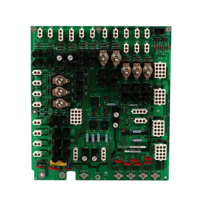
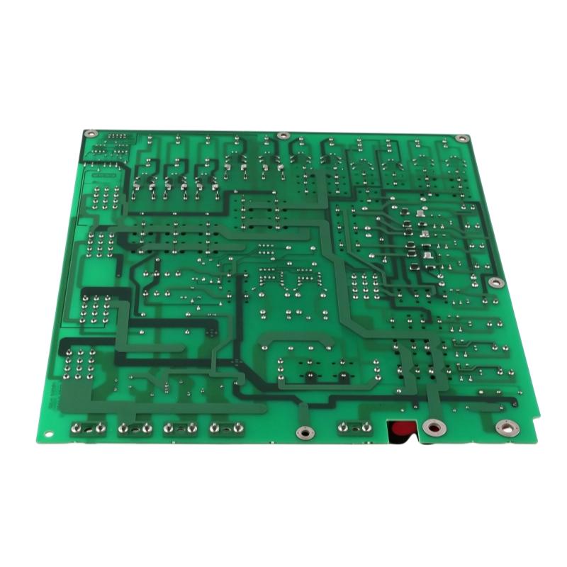
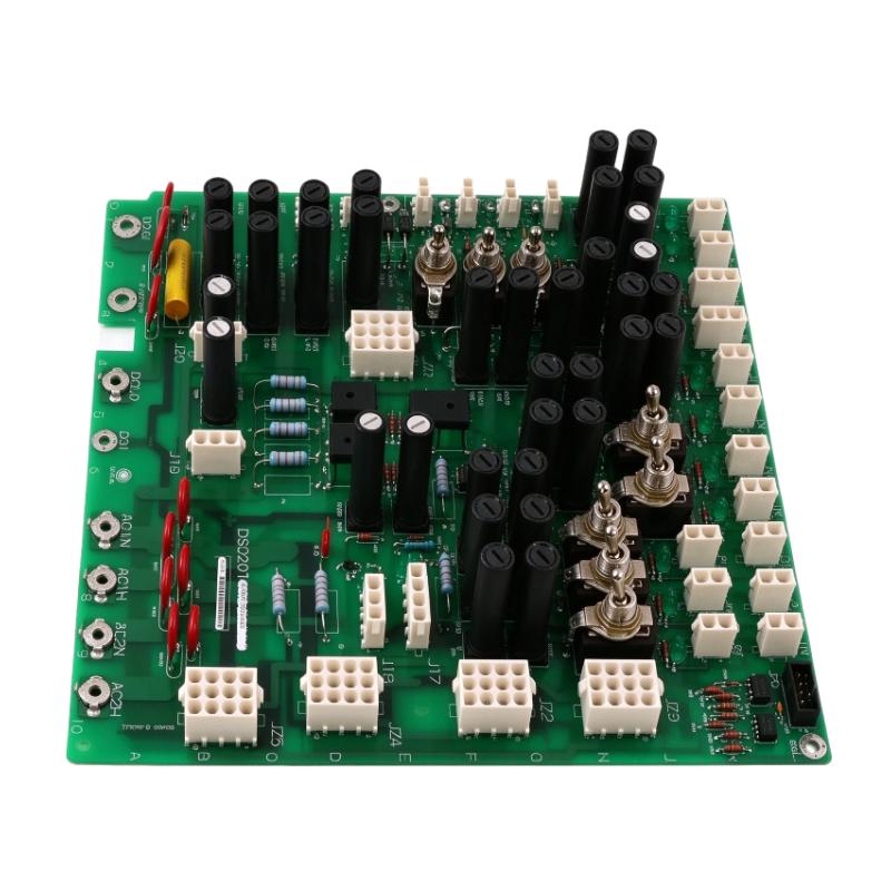
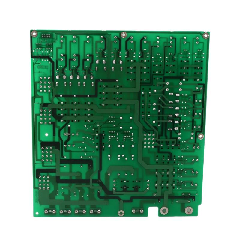
- GE
- DS200TCPDG2B
- Power Distribution Board
- USA
- 180 × 120 × 30 mm
- 0.454 kg
- Xiamen, China
- New & In Stock
- T/T, PayPal, Western Union
- 1 Year
- 1-3 Working Days
- DHL, UPS, TNT, FedEx and EMS.
- 24-Hour Service
- COO
- 7
Our advantage

Global Logistics
We have a 10-year logistics and express cooperation agreement, so our products can be shipped to any place in the world.

Brand new and original
Our products are imported in bulk from the place of origin. Because of the cooperative relationship, our products are all original and 100% new.

24-hour service
We provide 7*24 hours service to our customers. We will be there whenever you need us.

Price advantage
All our products are priced very favorably because we have our own warehouse and supply.
| Company Information | |||
| [email protected] | |||
| Mobile | +8615980777398 | ||
| +8615980777398 | |||
| 15980777398 |
Product Overview
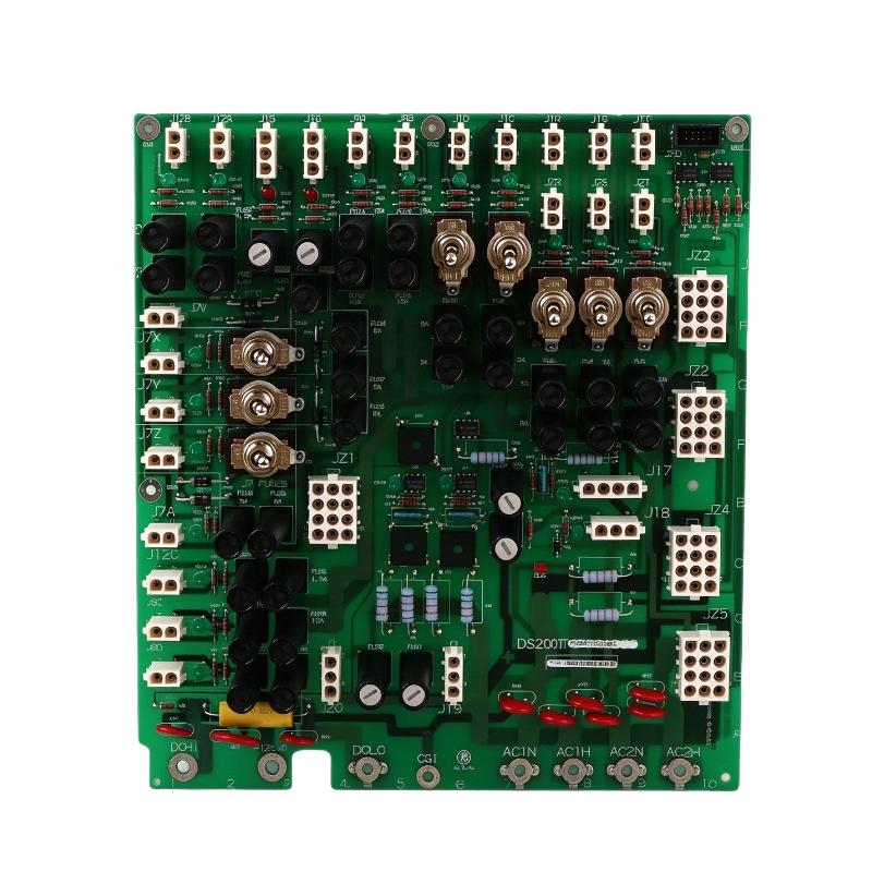
The GE DS200TCPDG2B Power Distribution Board is part of the Mark V Speedtronic turbine control system. Its primary job is to distribute electrical power to control-system cores and associated boards, allowing the turbine control hardware to operate from the required power sources. Unlike a processor or I/O board, the TCPD board focuses on power routing, circuit protection, and the controlled supply of power to different sections of the system.
In a gas turbine control cabinet, multiple control cores and interface boards require separate power connections. The DS200TCPDG2B distributes 125 V DC to designated control-system sections, including I/O cores, the Control Engine core, and TCEA boards. It also supports power distribution to specified terminal boards and the AC supply path used by ignition transformers.
The board includes individual toggle switches that allow designated control cores to be powered down for maintenance or troubleshooting. Its fuse arrangement and status LEDs help technicians identify the condition of the protected power-distribution circuits. These features are particularly useful when diagnosing a control cabinet in which one section has lost power while other sections remain operational.
When replacing this board, engineers should verify the complete part number and revision, the installed Mark V cabinet arrangement, connector assignments, and power-routing configuration. A board that fits the same general series is not automatically interchangeable if its wiring or revision differs from the installed unit.
Technical Specifications
| Parameter | Specification |
|---|---|
| Manufacturer | GE (General Electric) |
| Product Series | Mark V Speedtronic |
| Model | DS200TCPDG2B |
| Functional Acronym | TCPD |
| Product Type | Power Distribution Board |
| Primary Function | Distribution of control-system power |
| DC Power Distribution | 125 V DC to designated control-system sections |
| AC Power Distribution | Supports the specified 120/240 V AC ignition-transformer supply path |
| Toggle Switches | 8 |
| Fuses | 36 |
| Fuse Status Indicators | 36 OK LEDs |
| Signal Wire Terminals | 4 |
| Main Connector | 1 × 10-pin connector |
| PCB Coating | Normal coating |
| Installation | Mark V turbine control cabinet |
| Size | 180 × 120 × 30 mm |
| Weight | 0.454 kg |
Product Features
- Distributed DC power routing: Supplies 125 V DC to designated Mark V control cores and associated boards.
- Individual core switching: Eight toggle switches support the specified core power-control functions.
- Fuse-based circuit protection: Thirty-six fuses protect the applicable distribution circuits.
- Visual fuse-status indication: Dedicated OK LEDs help technicians locate a fuse-related problem during inspection.
- Multiple system connections: Signal terminals and the 10-pin connector support integration with the cabinet’s power-distribution wiring.
- Ignition power routing: Supports the specified AC supply path for ignition transformers.
- Mark V system integration: Works within the power-distribution architecture of compatible Speedtronic turbine control cabinets.
- Maintenance-oriented layout: Switches and indicators help isolate and diagnose individual power-distribution issues.
Working Principle
The DS200TCPDG2B receives power through the Mark V cabinet’s designated power connections and routes it to the control-system sections assigned to the TCPD board. Its function is to distribute the required supply voltages rather than execute turbine control algorithms or process field measurements.
A simplified power path is:
Cabinet Power Source → DS200TCPDG2B → Protected Distribution Circuits → Control Cores and Associated Boards
The board distributes 125 V DC to designated I/O cores, the Control Engine core, and TCEA boards. The power-distribution arrangement also supports the specified terminal-board supply connections and the 120/240 V AC path used by ignition transformers.
Each protected circuit uses its associated fuse. If a fuse opens because of an electrical fault or an abnormal load condition, the affected distribution path may lose power. The corresponding status indication helps maintenance personnel identify the circuit that requires investigation. A blown fuse should not simply be replaced repeatedly without checking the downstream wiring and load for the cause of the fault.
The eight toggle switches provide control over designated core power connections. During approved troubleshooting or maintenance procedures, technicians can use the applicable switch to isolate a supported section without treating the entire board as a general-purpose controller. The exact effect of each switch depends on its assigned core and the cabinet wiring.
The board’s power-routing function also depends on the surrounding Mark V hardware. Connectors, terminal wiring, grounding references, and any AC-to-DC conversion equipment must be correctly configured. A fault on the incoming supply, a downstream short circuit, or an incorrectly connected distribution path can affect the operation of connected control hardware.
Role in the Mark V Turbine Control Architecture
The DS200TCPDG2B occupies the power-distribution layer of the Mark V control cabinet. It supplies designated control-system sections and provides switching and fuse-status features that support maintenance and fault isolation.
Cabinet Power Inputs → TCPD Power Distribution Board → Control Cores / TCEA Boards / Terminal Boards
| System Element | Function |
|---|---|
| Cabinet Power Source | Supplies the electrical power routed by the distribution system |
| DS200TCPDG2B | Distributes power to designated Mark V system sections |
| I/O Cores | Host control-system input/output hardware |
| Control Engine Core | Hosts the designated turbine control processing hardware |
| TCEA Boards | Receive the required distributed power within the configured architecture |
| DTBC and DTBD Terminal Boards | Receive their specified power connections from the distribution arrangement |
| Ignition Transformers | Receive the applicable 120/240 V AC supply |
| Distribution Fuses | Protect individual power paths against qualifying overcurrent conditions |
| Toggle Switches | Control power to designated cores |
| CTBA Terminal Board | Monitors the specified power-distribution output in the applicable cabinet arrangement |
The TCPD board is one part of the overall turbine control power system. Correct operation depends on the upstream supply, downstream wiring, fuse condition, and compatibility of the connected boards.
Industrial Applications
| Application | Typical Use |
|---|---|
| Gas Turbine Control Systems | Distributing power to designated Mark V control hardware |
| Industrial Power Generation | Supporting the control electronics used in turbine-based generation |
| Turbine Control Cabinets | Routing power to I/O, processing, and interface boards |
| Ignition Systems | Supporting the specified power path for ignition transformers |
| Control System Maintenance | Isolating designated cores during approved troubleshooting procedures |
| Turbine Retrofit Projects | Replacing a matching TCPD board in an existing Mark V cabinet |
| Electrical Fault Investigation | Using fuse indicators and switching functions to help trace power-distribution problems |
| Industrial Plant Support Systems | Maintaining the power connections required by turbine control electronics |
The board is intended for the specific power-distribution arrangement of a compatible Mark V system. It should not be treated as a universal DC power distribution module for unrelated PLC or DCS platforms.
Installation and Maintenance
- Verify the complete part number: Confirm DS200TCPDG2B and check the board revision against the installed system documentation.
- Identify the cabinet configuration: Verify the Mark V core arrangement and the power connections assigned to the existing TCPD board.
- Isolate the power sources: Follow approved lockout procedures for both DC and AC supplies associated with the board.
- Document existing wiring: Record connector positions, terminal assignments, and switch positions before disconnecting the board.
- Inspect connectors and terminals: Check for damaged contacts, loose connections, discoloration, or signs of overheating.
- Check the incoming supply: Verify that the designated DC and AC sources match the cabinet wiring requirements.
- Inspect all fuses: Check the installed fuse types and ratings against the applicable system documentation before replacement.
- Review toggle-switch assignments: Confirm which core or distribution path each switch controls before operating it.
- Verify grounding references: Check the applicable grounding arrangement and any external-reference jumper configuration specified for the cabinet.
- Inspect downstream circuits: Investigate wiring faults or abnormal loads before restoring power to a circuit with a blown fuse.
- Perform staged power-up tests: Restore power according to the approved procedure and verify the expected status indications and operation of connected boards.
- Record the maintenance results: Document the board revision, fuse replacements, switch positions, voltage checks, and any corrective actions.
Work on the TCPD board must be performed by qualified personnel familiar with turbine control cabinets. Never assume that switching off one core removes all hazardous voltages from the board; separate DC and AC circuits may remain energized. Confirm isolation before handling connectors or replacing components.
Compatible System Components
The DS200TCPDG2B operates with the power connections and control hardware assigned to the Mark V turbine control architecture. The exact component arrangement depends on the cabinet configuration.
| Component | Function |
|---|---|
| Mark V Control Cabinet | Houses the TCPD board and associated turbine control hardware |
| Control Engine Core | Receives its designated power supply |
| I/O Cores | Receive power for the associated input/output hardware |
| TCEA Boards | Receive power through the specified distribution paths |
| DTBC Terminal Boards | Receive the applicable solenoid-output power connections |
| DTBD Terminal Boards | Receive their specified power connections |
| CTBA Terminal Board | Monitors the designated power-distribution output in the applicable arrangement |
| AC-to-DC Conversion Equipment | Supplies the specified DC power where used by the cabinet |
| Ignition Transformers | Use the designated AC power-distribution path |
| Compatible Fuses | Protect the corresponding distribution circuits |
| Cabinet Wiring and Connectors | Carry power between the TCPD board and connected equipment |
Recommended Related Models
The following GE boards belong to or are associated with the Mark V turbine control hardware family. Their functions differ, so verify the cabinet location, revision, connectors, and power requirements before selecting a related board.
| Model | Product Type | Relevance |
|---|---|---|
| GE DS200TCPDG2 | Power Distribution Board | Parent TCPD board designation |
| GE DS200TCPDG1 | Power Distribution Board | Related TCPD board variant |
| GE DS200PTBAG1 | Terminal Board | Related Mark V cabinet interface hardware |
| GE DS200DTBCG1 | Terminal Board | Related terminal-board hardware used in turbine control systems |
| GE DS200DTBDG1 | Terminal Board | Related terminal-board hardware |
| GE DS200TCEA | Control Electronics Board | Related Mark V control-system board family |
Key Advantages
- Distributes power to designated Mark V control-system sections.
- Provides individual switching for supported core power paths.
- Uses fuses to protect applicable distribution circuits.
- Includes LED indications for fuse-status checks.
- Supports the specified DC and ignition-related AC power paths.
- Simplifies power-distribution troubleshooting within compatible turbine control cabinets.
Technical FAQs
Which Mark V components receive power from the DS200TCPDG2B?
The board distributes 125 V DC to designated I/O cores, the Control Engine core, and TCEA boards. It also supplies specified terminal-board power connections and the AC supply path used by ignition transformers, depending on the cabinet arrangement.
What should be checked when one control core loses power but other cores remain operational?
Inspect the relevant toggle-switch position, associated fuse and status LED, incoming supply, and downstream wiring for that core. Confirm the assigned power path from the cabinet drawings before replacing a fuse or changing a switch position.
Why might a replacement TCPD board fail to power the same circuits as the original?
Differences in board revision, connector assignments, grounding-reference configuration, or cabinet wiring can affect compatibility. Compare the complete part number and revision, then verify each connection against the installed Mark V configuration before energizing the replacement.
Does the DS200TCPDG2B distribute power to every Mark V I/O core directly?
No. The distribution arrangement includes designated power paths, and some digital I/O cores receive power through their associated I/O core rather than directly from the TCPD board. Confirm the actual core architecture and wiring when tracing a power fault.