

ProductPRODUCT
Featured products
Contact Us
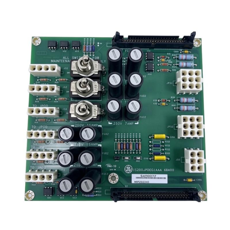
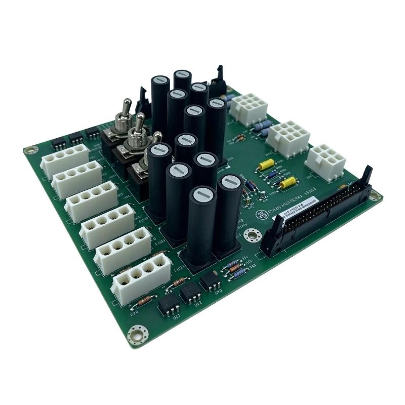
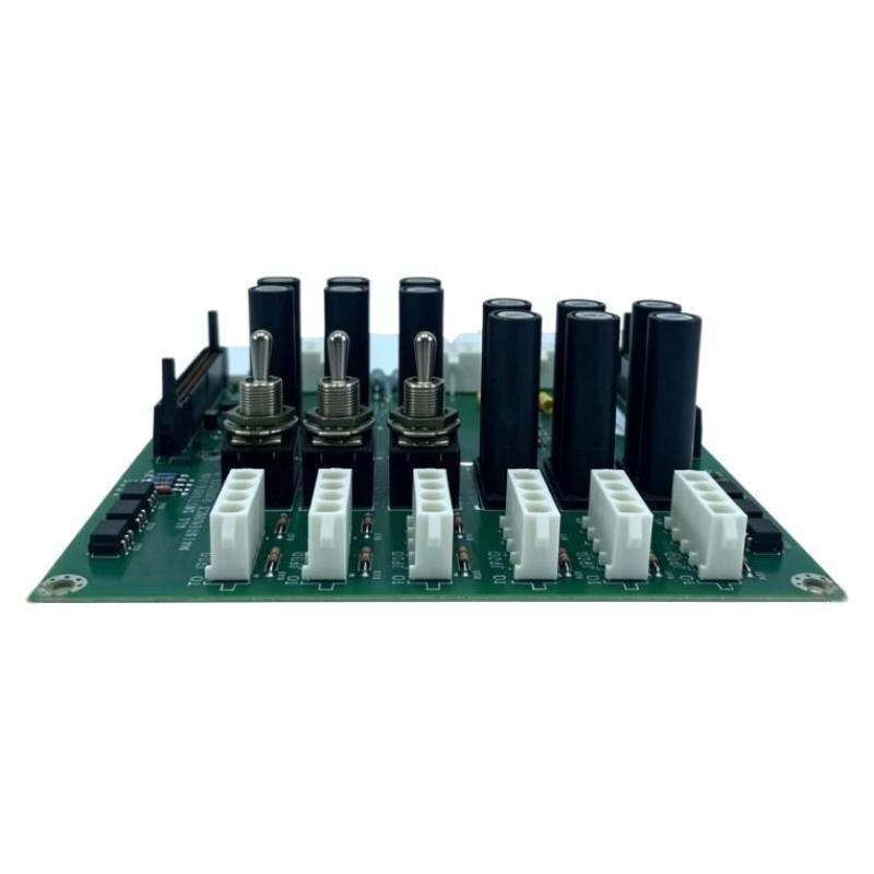
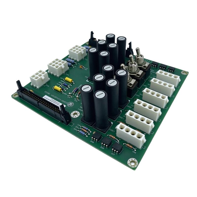
- GE
- IS200JPDEG1ABB
- DC Battery Power Distribution Board
- USA
- 170 × 25 × 150 mm
- 0.45 kg
- Xiamen, China
- New & In Stock
- T/T, PayPal, Western Union
- 1 Year
- 1-3 Working Days
- DHL, UPS, TNT, FedEx and EMS.
- 24-Hour Service
- COO
- 5
Our advantage

Global Logistics
We have a 10-year logistics and express cooperation agreement, so our products can be shipped to any place in the world.

Brand new and original
Our products are imported in bulk from the place of origin. Because of the cooperative relationship, our products are all original and 100% new.

24-hour service
We provide 7*24 hours service to our customers. We will be there whenever you need us.

Price advantage
All our products are priced very favorably because we have our own warehouse and supply.
| Company Information | |||
| [email protected] | |||
| Mobile | +8615980777398 | ||
| +8615980777398 | |||
| 15980777398 |
Product Overview
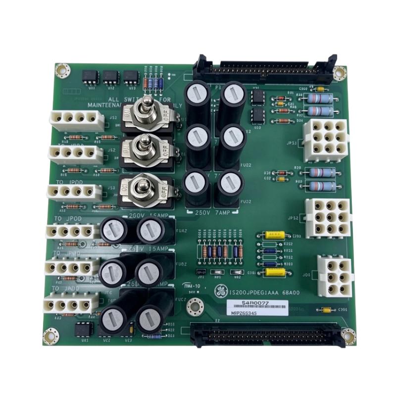
The GE IS200JPDEG1ABB DC Battery Power Distribution Board is part of the Mark VIe turbine control system’s power distribution architecture. Identified by the functional acronym JPDE, the board receives DC power from battery supplies or compatible power supplies and distributes it to designated terminal boards and other control-system loads.
In a turbine control cabinet, several terminal boards and associated control components depend on a consistent DC supply. The JPDE board organizes these power connections and supports monitoring of the DC distribution system through feedback signals routed to the PPDA I/O pack. This feedback helps the control system identify abnormal bus-voltage conditions, including ground faults in a properly configured floating DC system.
The board supports two power-supply inputs and can operate with 24 V DC or 48 V DC supplies. In battery-powered installations, its distribution arrangement is used alongside the associated DC circuit breaker and input filter. This makes the JPDE relevant to maintenance work involving turbine control power, battery-backed supplies, and faults affecting multiple downstream circuits.
The IS200JPDEG1ABB designation should be checked against the installed board and cabinet configuration before replacement. Connector assignments, grounding arrangements, jumper positions, and the feedback-cable path all affect how the board operates within the power distribution module. Matching the general JPDE description alone is not sufficient to establish complete interchangeability.
Technical Specifications
| Parameter | Specification |
|---|---|
| Manufacturer | GE (General Electric) |
| Product Series | Mark VIe |
| Model | IS200JPDEG1ABB |
| Functional Acronym | JPDE |
| Product Type | DC Battery Power Distribution Board |
| Primary Function | DC power distribution to terminal boards and system loads |
| DC Operating Voltage | 24 V DC or 48 V DC |
| Power-Supply Inputs | 2 |
| Total DC Current Rating | 30 A across all branch circuits, according to the JPDE platform documentation |
| Maximum Nominal Voltage | 50 V |
| Feedback Interface | P1/P2 diagnostic ribbon-cable connections |
| Monitoring Function | DC bus-voltage and distribution-circuit feedback through PPDA |
| Grounding Arrangement | Floating DC bus with optional earth-centering resistors |
| Mounting | Vertical mounting on a metal bracket in the power distribution cabinet |
| Size | 170 × 25 × 150 mm |
| Weight | 0.45 kg |
Product Features
- DC battery power distribution: Routes DC power from battery or power-supply inputs to designated terminal boards and system loads.
- Dual supply inputs: Supports two power-supply connections within the configured distribution arrangement.
- 24 V and 48 V operation: Accommodates the supported DC supply configurations.
- Bus-voltage feedback: Sends voltage-monitoring information through the PPDA feedback architecture.
- Ground-fault monitoring support: Allows the system to detect ground faults when the DC bus and grounding resistors are configured appropriately.
- Branch-circuit protection: Uses fuses to protect the associated distribution circuits.
- Diagnostic ribbon connections: P1 and P2 provide the feedback path between compatible power distribution boards and the PPDA interface.
- Cabinet-level integration: Works with other JPDE, JPDB, JPDF, JPDS, or JPDM boards where the documented feedback architecture permits.
- Maintenance access: The board’s connectors and mounting arrangement support inspection and replacement within the power distribution cabinet.
Working Principle
The IS200JPDEG1ABB receives DC power from the connected battery or power supplies and distributes it to the designated downstream circuits. Its role is to manage power routing and provide feedback about selected electrical conditions rather than perform turbine control calculations.
A simplified arrangement is:
Battery / DC Power Supplies → JPDE Distribution Board → Protected DC Branch Circuits → Terminal Boards and System Loads
The board supports two power-supply inputs and operates with a 24 V DC or 48 V DC distribution arrangement. The incoming supply is routed through the board to the appropriate output connections. Fuses protect individual branches, while the overall current rating limits the amount of current that can be carried through the board’s conventional construction.
The JPDE also supports monitoring through the power distribution module’s PPDA I/O pack. Voltage feedback from the positive and negative sides of the DC bus allows the control system to evaluate the condition of the supply. When the system uses a floating DC bus, the board’s grounding resistors can center the bus relative to earth. This arrangement enables ground-fault detection through voltage feedback when the required jumper and grounding configuration are in place.
The P1 and P2 diagnostic ribbon connectors form part of the feedback chain. P1 sends feedback toward the board hosting the PPDA I/O pack, while P2 receives feedback from other compatible distribution boards and passes it along. Correct cable routing is therefore important when multiple power distribution boards share the same monitoring path.
The board is not intended to supply the bulk 500 W converters used to generate 28 V control power for I/O packs. Those loads require the appropriate power-distribution equipment. During troubleshooting, engineers should distinguish between a missing incoming supply, a blown branch fuse, a downstream wiring fault, and a ground fault indicated by the monitoring system.
Role in the Mark VIe Power Distribution Architecture
The JPDE board forms part of the DC power distribution and diagnostic layer in the Mark VIe control cabinet. It supplies designated loads and contributes bus-voltage feedback to the wider power distribution monitoring arrangement.
Battery / DC Supplies → JPDE → Protected Distribution Branches → Terminal Boards and System Loads
JPDE P1/P2 Feedback → PPDA I/O Pack → Mark VIe Control System
| System Element | Function |
|---|---|
| Battery Supply | Provides DC power in battery-backed installations |
| DC Power Supplies | Supply the configured 24 V DC or 48 V DC inputs |
| IS200JPDEG1ABB | Distributes DC power and supports bus-voltage feedback |
| Branch Fuses | Protect individual output circuits |
| Terminal Boards | Receive power for designated control-system functions |
| Compatible JPDB / JPDF / JPDS / JPDM Boards | Participate in the documented distribution feedback arrangement |
| PPDA I/O Pack | Receives and processes power-distribution feedback signals |
| Ground-Centering Resistors | Establish the intended relationship between the floating DC bus and earth |
| Grounding Jumper JP1 | Connects the centering resistors to earth when the required configuration calls for it |
| Diagnostic Ribbon Cables | Carry feedback signals between distribution boards and the PPDA interface |
| DC Circuit Breaker and Input Filter | Support the battery-powered distribution arrangement where specified |
The final arrangement depends on whether the installation uses one or two supplies, the selected bus voltage, and the cabinet’s grounding design. These details must be verified before changing jumpers or reconnecting the feedback cables.
Industrial Applications
| Application | Typical Use |
|---|---|
| Gas Turbine Control Cabinets | Distributing DC power to designated control-system loads |
| Steam Turbine Control Systems | Supporting compatible turbine-control power distribution arrangements |
| Battery-Backed Control Power | Routing DC power from battery supplies to terminal boards and other loads |
| Industrial Power Generation | Maintaining the DC supply architecture for turbine control equipment |
| Mark VIe Power Distribution Modules | Providing branch distribution and feedback within the cabinet |
| Control-System Ground-Fault Monitoring | Supporting detection of ground faults on a properly configured floating DC bus |
| Turbine Maintenance and Troubleshooting | Investigating supply interruptions, branch-fuse faults, and voltage-feedback alarms |
| Turbine Control System Retrofit | Replacing a matching JPDE board after verifying the installed configuration |
The JPDE is intended for the specified DC distribution architecture. It should not be substituted for a general-purpose power supply or a different Mark VIe distribution board without checking the intended voltage, load type, feedback arrangement, and mounting configuration.
Installation and Maintenance
- Verify the complete part number: Confirm IS200JPDEG1ABB and check the board revision against the installed Mark VIe documentation.
- Identify the supply arrangement: Determine whether the installation uses one or two DC power supplies and confirm the intended bus voltage.
- Isolate all power sources: Follow approved lockout procedures for battery supplies and associated DC power circuits before handling the board.
- Document the existing connections: Record P1/P2 ribbon-cable routing, power connectors, branch connections, and jumper positions before removal.
- Inspect the mounting bracket: Check the metal bracket, fasteners, grounding contact, and board support for damage or looseness.
- Verify the input supply: Confirm that the connected supply is configured for the required 24 V DC or 48 V DC operation.
- Inspect branch fuses: Check fuse ratings and condition against the applicable circuit documentation. Investigate the cause of a blown fuse before replacing it.
- Check grounding configuration: Verify the floating-bus arrangement and confirm whether JP1 must connect the centering resistors to earth.
- Inspect the P1/P2 feedback path: Check ribbon cables, connector seating, and routing to the PPDA interface and adjacent distribution boards.
- Verify downstream loads: Confirm that terminal-board connections and branch wiring match the approved power distribution diagram.
- Perform power and feedback checks: Restore power according to the commissioning procedure and verify the DC bus readings, branch status, and PPDA feedback.
- Record maintenance results: Document the supply configuration, jumper position, fuse replacements, cable routing, and test results.
The DC battery supply may remain hazardous even when the turbine control system is not operating. Confirm electrical isolation before disconnecting the board. Do not alter the grounding jumper solely to clear a ground-fault indication; first determine the intended grounding scheme and investigate the fault.
Compatible System Components
The IS200JPDEG1ABB operates with the DC supply equipment, terminal boards, and feedback components assigned to the Mark VIe power distribution arrangement. Compatibility depends on the actual cabinet design and the documented P1/P2 feedback connections.
| Component | Function |
|---|---|
| DC Battery Supply | Provides battery-backed power where used |
| 24 V DC / 48 V DC Power Supplies | Supply the supported JPDE input voltage |
| DC Circuit Breaker | Provides upstream protection in the specified battery-powered arrangement |
| 30 A Input Filter | Supports the battery input arrangement where specified |
| Terminal Boards | Receive distributed DC power for designated system functions |
| JPDB Power Distribution Board | Participates in compatible power distribution feedback arrangements |
| JPDF Power Distribution Board | Participates in compatible power distribution feedback arrangements |
| JPDS DC Power Distribution Board | Distributes DC power in the wider control-system architecture |
| JPDM Power Distribution Board | Provides related power distribution and feedback functionality where supported |
| PPDA I/O Pack | Receives power-distribution monitoring signals |
| P1/P2 Diagnostic Ribbon Cables | Carry feedback signals between compatible boards |
| Grounding Jumper and Centering Resistors | Support the specified floating-bus grounding and monitoring arrangement |
Recommended Related Models
The following GE models are related to Mark VIe power distribution. Their functions and electrical arrangements differ, so verify the required supply type, output configuration, feedback interface, and mounting method before choosing a related component.
| Model | Product Type | Relevance |
|---|---|---|
| GE IS200JPDBG1ABB | AC Power Distribution Board | Related Mark VIe distribution board for AC power |
| GE IS200JPDFG1ACC | DC Power Distribution Board | Related power distribution hardware within the Mark VIe family |
| GE IS200JPDSG1ABB | DC Power Distribution Board | Related DC distribution board for the control system |
| GE IS200JPDMG1A | Power Distribution Board | Related board in the Mark VIe power distribution architecture |
| GE IS200JPDHG1A | I/O Pack Power Distribution Board | Related distribution hardware for I/O pack power |
| GE IS200JPDLG1A | Local Pack DC Power Distribution Board | Related board for local DC power distribution |
Key Advantages
- Distributes DC power to designated turbine control-system loads.
- Supports 24 V DC and 48 V DC supply arrangements.
- Accepts two power-supply inputs.
- Provides feedback for bus-voltage and distribution monitoring.
- Supports ground-fault detection on a correctly configured floating DC bus.
- Integrates with compatible Mark VIe distribution boards and the PPDA monitoring interface.
Technical FAQs
What is the difference between the JPDE board and a standard DC power supply?
The JPDE is a power distribution board, not a standalone voltage-conversion unit. It receives DC power from batteries or compatible power supplies and routes it to designated loads while providing distribution feedback. The upstream equipment must supply the required DC voltage.
How does the IS200JPDEG1ABB support ground-fault detection?
The JPDE provides positive and negative DC bus-voltage feedback through the PPDA monitoring arrangement. When the DC bus is intended to float relative to earth, the centering resistors and JP1 jumper can establish the required reference for detecting ground faults. The jumper must be configured according to the system grounding design.
What should be checked if the Mark VIe system reports a DC distribution fault?
Check the incoming supply voltage, branch fuses, output wiring, P1/P2 feedback cables, and PPDA diagnostic information. If a ground-fault indication is present, inspect the bus grounding arrangement and downstream circuits rather than changing the grounding jumper without diagnosis.
Can the JPDE board directly power the bulk converters used for I/O pack control power?
No. The JPDE documentation states that it is limited by the current capacity of conventional board construction and does not supply the bulk 500 W converters that convert 24 V input to 28 V output for I/O pack control power. Those converters require the appropriate power-distribution arrangement.