

ProductPRODUCT
Featured products
Contact Us
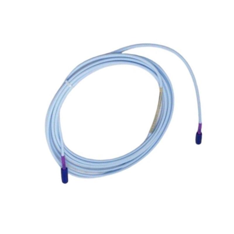
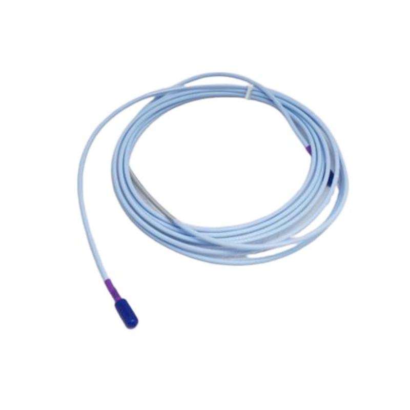
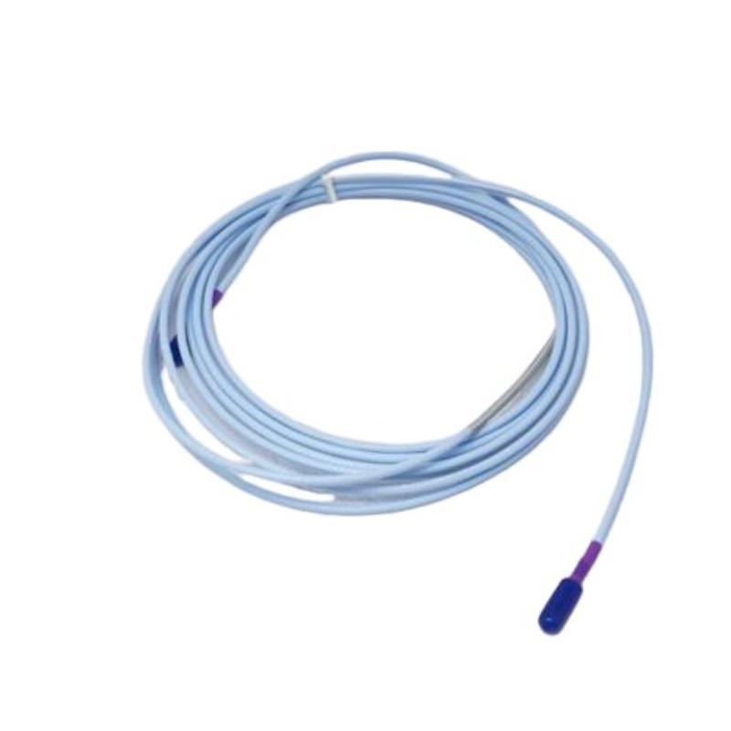
- Bently Nevada
- 330730-080-12-05
- 3300 XL 11mm Extension Cable
- USA
- 8.0 m
- 0.36kg
- Xiamen, China
- New & In Stock
- T/T, PayPal, Western Union
- 1 Year
- 1-3 Working Days
- DHL, UPS, TNT, FedEx and EMS.
- 24-Hour Service
- COO
- 12
Our advantage

Global Logistics
We have a 10-year logistics and express cooperation agreement, so our products can be shipped to any place in the world.

Brand new and original
Our products are imported in bulk from the place of origin. Because of the cooperative relationship, our products are all original and 100% new.

24-hour service
We provide 7*24 hours service to our customers. We will be there whenever you need us.

Price advantage
All our products are priced very favorably because we have our own warehouse and supply.
| Company Information | |||
| [email protected] | |||
| Mobile | +8615980777398 | ||
| +8615980777398 | |||
| 15980777398 |
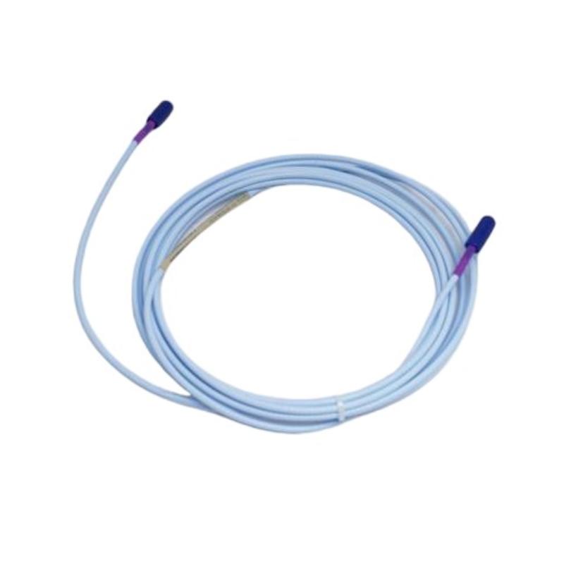
Bently Nevada 330730-080-12-05 Extension Cable — Product Details, Specifications, Applications, and Related Models
1. Product Overview
The Bently Nevada 330730-080-12-05 is an extension cable component for the 3300 XL 11 mm Proximity Transducer System. It connects a compatible proximity probe to its matching Proximitor Sensor, providing the electrical connection needed for shaft vibration and relative displacement measurements in industrial machinery.
This model has a nominal cable length of 8.0 m (26.2 ft) and uses the FluidLoc cable with connector protector configuration. The cable is not armored in this configuration. The FluidLoc design is intended to limit fluid migration through the cable interior, while the connector protector helps protect the connection area during handling and installation.
The extension cable is a passive component, not a standalone sensor. Its electrical characteristics and length must match the probe and Proximitor Sensor to form a correctly configured measurement system.
The final suffix 05 identifies the multiple-agency approval option. The specific approvals applicable to the supplied unit should be verified against its markings and documentation before use in regulated or hazardous-area installations.
2. Basic Product Information
| Parameter | Specification |
|---|---|
| Brand | Bently Nevada |
| Model number | 330730-080-12-05 |
| Product name | 3300 XL 11 mm Extension Cable |
| Product series | 3300 XL 11 mm Proximity Transducer System |
| Product category | Industrial proximity transducer extension cable |
| Cable length code | 080 |
| Nominal cable length | 8.0 m |
| Equivalent length | Approximately 26.2 ft |
| Cable and connector option | 12 — FluidLoc cable with connector protector |
| Cable armor | Not fitted |
| FluidLoc construction | Yes |
| Connector protector | Included |
| Agency approval option | 05 — multiple-agency approval option |
| Cable type | 75 Ω triaxial |
| Insulation material | FEP (fluoroethylene propylene) |
| Connector type | Compatible ClickLoc-style connector |
| Typical connector material | Gold-plated brass |
| Main function | Connects a compatible probe to its Proximitor Sensor |
| Typical application | Shaft vibration and displacement monitoring |
| Typical cable weight | Approximately 0.36 kg |
| Approximate cable dimensions | 8.0 m length; exact diameter and connector dimensions depend on the applicable drawing |
| Packed dimensions | Packaging-dependent |
| Shipping weight | Packaging-dependent; confirm with the supplier |
| Operating temperature | Approximately −51°C to +177°C for the cable family; verify the exact applicable specification |
| Power requirement | No independent power supply; passive cable assembly |
3. Detailed Technical Specifications
The 330730-080-12-05 is designed to maintain the electrical connection within a compatible proximity measurement loop. The specifications below describe the cable itself; they should not be confused with the performance specifications of the complete probe-cable-Proximitor system.
| Technical parameter | Specification |
|---|---|
| Full model number | 330730-080-12-05 |
| Measurement system | 3300 XL 11 mm |
| Cable length | 8.0 m |
| Cable length in feet | 26.2 ft |
| Cable construction | FluidLoc, without armor |
| Connector protection | Connector protector fitted |
| Electrical design | 75 Ω triaxial cable |
| Insulation | FEP |
| Typical capacitance | 69.9 pF/m |
| Capacitance per foot | 21.3 pF/ft |
| Center-conductor resistance | 2.0 ± 0.5 Ω for the specified 8 m assembly |
| Coaxial-conductor resistance | 0.6 ± 0.2 Ω for the specified 8 m assembly |
| Typical cable mass per metre | 45 g/m |
| Calculated cable mass for 8.0 m | Approximately 0.36 kg |
| Minimum bend radius | 25.4 mm (1.0 in), subject to the applicable installation instructions |
| Cable outside diameter | Approximately 3.9 mm for the unarmored cable section; verify the exact drawing |
| Connector arrangement | Compatible ClickLoc-style connection with connector protector |
| Connector material | Gold-plated brass in the applicable configuration |
| Connector tightening | Finger-tight connection; follow the applicable installation instructions |
| Maximum connector torque | Approximately 0.565 N·m where specified for the applicable connector |
| Operating temperature | Approximately −51°C to +177°C for the cable family; confirm the applicable rating |
| Approval option | 05 — multiple-agency approval option |
| Net cable weight | Approximately 0.36 kg, calculated from typical cable mass |
| Shipping weight | Not fixed; depends on packaging and accessories |
| Overall cable length | 8.0 m nominal |
| Connector-protector dimensions | Confirm against the applicable product drawing |
| Shipping package dimensions | Packaging-dependent |
| Independent power consumption | None |
| Primary function | Transmits the proximity probe signal to the Proximitor Sensor |
The calculated cable mass of 0.36 kg is based on a typical cable mass of 45 g/m multiplied by 8.0 m. The delivered assembly may have a different measured weight due to connector components and packaging.
4. Product Introduction
The Bently Nevada 330730-080-12-05 is intended for installations that use the 3300 XL 11 mm proximity transducer system. It provides the electrical connection between a compatible proximity probe and the corresponding Proximitor Sensor.
A proximity probe measures changes in the gap between its sensing tip and a conductive target, commonly a rotating shaft. As the shaft moves, the probe’s electrical response changes. The Proximitor Sensor conditions that response so compatible machinery monitoring equipment can use it to assess shaft movement and vibration.
The extension cable is a necessary part of this measurement chain. Its length, capacitance, resistance, connector condition, and compatibility influence the electrical behavior of the complete system. An unsuitable cable can affect measurement performance even when the probe and monitoring equipment are otherwise functioning correctly.
The 8.0 m length is useful where the probe and Proximitor Sensor must be installed some distance apart. The FluidLoc construction is intended to limit fluid migration through the cable interior, and the connector protector helps protect the connection area during installation and maintenance.
This model is therefore best suited to applications where the exact cable length, connector arrangement, and electrical configuration are specified as part of an existing or newly designed measurement system.
5. Product Applications
5.1 Steam turbines
Steam turbines operate at high rotational speeds and require careful monitoring of mechanical behavior. Proximity measurement systems can be used to monitor shaft vibration and relative shaft displacement.
The 330730-080-12-05 connects the compatible probe to the Proximitor Sensor, allowing the measurement signal to reach the signal-conditioning component. A correctly installed cable helps maintain a stable connection for ongoing monitoring.
5.2 Gas turbines and generators
Gas turbines and generators may operate continuously for long periods, making reliable monitoring and maintenance planning important.
The cable’s 8.0 m length allows flexibility when positioning the probe and Proximitor Sensor. Its suitability depends on the actual installation temperature, routing, connector protection requirements, and compatibility with the installed system.
5.3 Centrifugal compressors
Centrifugal compressors are often monitored for shaft vibration and relative displacement. Changes in these measurements can help maintenance teams investigate developing mechanical problems.
The extension cable carries the probe signal to the Proximitor Sensor. Keeping the cable and connectors in good condition helps reduce the risk of intermittent signals and unnecessary troubleshooting.
5.4 Industrial pumps
Large industrial pumps may use proximity probes where shaft displacement monitoring is required by the equipment design.
The FluidLoc construction may be useful in installations where contact with oil or other fluids is a concern. However, the cable should only be used where its documented material and temperature limits suit the actual operating environment.
5.5 Other rotating machinery
The cable may also be used in other installations that employ a compatible 3300 XL 11 mm proximity measurement system.
Typical applications include continuous machinery monitoring, vibration trend analysis, and support for planned maintenance. The cable itself does not perform the analysis; it provides the connection needed for the larger monitoring system to function.
6. Product Advantages
6.1 FluidLoc construction
The FluidLoc cable design is intended to restrict the migration of oil and other liquids through the cable interior.
This feature can be useful in machinery environments where fluids may come into contact with the cable. Correct routing, connector handling, and regular inspection are still necessary.
6.2 Connector protector
The connector protector helps protect the connection area during installation, routine maintenance, and handling.
This is particularly useful where technicians must route cables through confined spaces or work around other machinery components. Adequate clearance should be allowed so the protector is not crushed or forced against adjacent equipment.
6.3 Electrical characteristics designed for the system
The 75 Ω triaxial construction and specified cable capacitance are intended for use within the compatible proximity measurement system.
Using the correct cable helps maintain the electrical characteristics required by the probe and Proximitor Sensor. An ordinary cable with different characteristics should not be substituted without explicit technical approval.
6.4 Practical 8.0 m length
The 8.0 m length can accommodate installations where the sensing probe and Proximitor Sensor are not located close together.
Choosing the correct cable length helps avoid unnecessary cable loops, unsuitable routing, and unauthorized modifications. The total probe-plus-extension length must match the selected Proximitor Sensor configuration.
6.5 Straightforward replacement
The pre-terminated cable assembly can simplify replacement work because it reduces the need for field termination.
Maintenance personnel should still verify the complete part number, inspect the connectors, and confirm compatibility with the installed probe and Proximitor Sensor before returning the equipment to service.
6.6 Supports stable machinery measurements
When correctly matched and installed, the cable supports the transmission of the signal used by the proximity measurement system.
Reliable signal transmission contributes to the quality of the data available for condition monitoring, but overall performance depends on the complete system, correct installation, and appropriate monitoring configuration.
6.7 Defined ordering configuration
The model number identifies the cable length and construction option. This helps maintenance teams specify replacement parts without treating every cable in the same product family as interchangeable.
The 05 approval option is relevant to projects that require multiple-agency approvals. The actual approvals applicable to a delivered unit should be verified against its documentation.
7. Brand and Product Series
| Item | Description |
|---|---|
| Brand | Bently Nevada |
| Series | 3300 XL |
| Product family | 3300 XL 11 mm Proximity Transducer System |
| Product type | Extension cable |
| Model | 330730-080-12-05 |
| Cable length | 8.0 m |
| Cable construction | FluidLoc |
| Connector protection | Included |
| Armor | Not fitted |
| Primary purpose | Connects a compatible proximity probe to its Proximitor Sensor |
| Typical industry | Industrial machinery monitoring |
| Related components | Compatible 3300 XL 11 mm probes, Proximitor Sensors, and monitoring equipment |
The 3300 XL 11 mm product family uses components designed to operate together as a matched measurement system. A proximity probe, extension cable, and Proximitor Sensor must be compatible in terms of electrical characteristics and total system length.
The cable is not a direct substitute for a monitoring module or a Proximitor Sensor. Each component has a different role in the measurement chain.
8. Five Related Models in the Same Series
The following models are related extension-cable configurations or components from the same proximity transducer family. Their option codes and lengths should be checked carefully before substitution.
| Model | Product type | Main parameters | Dimensions | Weight (kg) |
|---|---|---|---|---|
| 330730-080-12-00 | 3300 XL 11 mm extension cable | 8.0 m; FluidLoc; connector protector; approval option 00 | Cable length 8.0 m; exact connector dimensions require drawing | Approx. 0.36 kg |
| 330730-080-13-05 | 3300 XL 11 mm extension cable | 8.0 m; armored FluidLoc configuration with connector protectors; multiple-agency approval option | Cable length 8.0 m; armor and connector dimensions require drawing | Configuration-dependent; verify |
| 330730-080-11-05 | 3300 XL 11 mm extension cable | 8.0 m; armored FluidLoc configuration; multiple-agency approval option | Cable length 8.0 m; exact assembly dimensions require drawing | Approx. 1.12 kg as an estimate based on 140 g/m armored-cable mass; verify |
| 330730-080-10-05 | 3300 XL 11 mm extension cable | 8.0 m; FluidLoc option; multiple-agency approval option; confirm exact option details | Cable length 8.0 m; exact connector dimensions require drawing | Configuration-dependent; verify |
| 330730-040-12-05 | 3300 XL 11 mm extension cable | 4.0 m; FluidLoc cable with connector protector; multiple-agency approval option | Cable length 4.0 m; exact connector dimensions require drawing | Approx. 0.18 kg as a length-based estimate; verify |
These models provide a starting point for comparing cable length, construction, and approval configuration. The 00 and 05 suffixes are not equivalent approval options, and armored configurations may have different dimensions and weights from unarmored cables.
The estimated weights above are reference values, not guaranteed factory weights for every supplied configuration. Before ordering, confirm the full part number and its mechanical and electrical characteristics against the intended system.
9. Five Other Commonly Used Models from the Same Brand
These products are associated with proximity measurement and machinery condition monitoring. They have different functions and should not be treated as direct replacements for the extension cable.
| Model | Product name / type | Main parameters and function | Dimensions | Weight (kg) |
|---|---|---|---|---|
| 330101-00-08-10-02-00 | 3300 XL 8 mm proximity probe | Probe for a compatible 8 mm proximity measurement system; confirm exact probe and thread configuration | Configuration-dependent; refer to drawing | Not confirmed |
| 330103-00-08-10-02-00 | 3300 XL 8 mm proximity probe | Proximity sensing component for suitable industrial machinery applications | Configuration-dependent; refer to drawing | Not confirmed |
| 330104-00-08-10-02-00 | 3300 XL 8 mm proximity probe | Probe component for compatible proximity measurement installations | Configuration-dependent; refer to drawing | Not confirmed |
| 330180-50-00 | Proximitor Sensor | Signal-conditioning component for a compatible proximity transducer system | Housing and mounting dimensions require the applicable drawing | Not confirmed |
| 3500/42M | Machinery monitoring module | Monitoring module used in compatible machinery protection and condition-monitoring arrangements | Rack-mounted; exact dimensions depend on hardware configuration | Not confirmed |
The proximity probe detects changes in the gap between its sensing tip and a conductive target. The extension cable carries the signal to the Proximitor Sensor, which conditions it for use by the wider monitoring system. A monitoring module then processes the available signals according to its configuration.
These products are examples of related equipment rather than interchangeable components. Confirm the installed system family, complete model number, and physical specifications before selecting a replacement or planning an upgrade.
10. Installation and Maintenance Recommendations
Before installation
– Confirm that the full model number is 330730-080-12-05.
– Verify that the cable length and connector option match the intended system.
– Confirm compatibility with the installed proximity probe and Proximitor Sensor.
– Inspect the cable jacket, connector protector, and connector contacts for damage.
– Check that the installation environment is within the specified temperature and material limits.
– Verify the actual approval markings and documentation where regulatory approvals are required.
During installation
– Follow the applicable connector installation procedure.
– Route the cable away from sharp edges, crushing points, and unsuitable hot surfaces.
– Observe the specified minimum bend radius.
– Avoid pulling directly on the connector or using the connector protector as a pulling handle.
– Do not cut, splice, or modify the cable unless the applicable instructions explicitly permit it.
– Leave sufficient space around the connector to allow inspection and future maintenance.
After installation
– Verify that the cable is connected securely at both ends.
– Perform the required continuity and system checks using the approved procedure.
– Confirm that the monitoring channel produces plausible readings under the commissioning conditions.
– Record the installed part number and configuration in the maintenance documentation.
– Check the complete measurement loop before returning critical machinery to service.
Routine maintenance
Inspect the cable periodically for damaged insulation, loose connectors, contamination, liquid exposure, and signs of mechanical stress.
If the measurement signal becomes unstable, check the probe, cable, Proximitor Sensor, connectors, and associated monitoring equipment. Replacing the cable without checking the rest of the measurement chain may not resolve the underlying issue.
11. Dimensions and Weight Reference
| Physical parameter | Value |
|---|---|
| Nominal cable length | 8.0 m |
| Length in feet | Approximately 26.2 ft |
| Cable outside diameter | Approximately 3.9 mm for the unarmored cable section; verify the drawing |
| Minimum bend radius | 25.4 mm |
| Connector protector | Included |
| Exact connector-protector dimensions | Not confirmed |
| Net cable weight | Approximately 0.36 kg |
| Shipping weight | Depends on packaging and accessories |
| Shipping package dimensions | Packaging-dependent |
| Mounting dimensions | Not applicable to the cable itself; installation clearance must be checked |
The 0.36 kg value is based on the typical cable mass of 45 g/m over an 8.0 m length. It should be treated as a nominal reference rather than a guaranteed packaged weight.
For a formal engineering specification, procurement document, or shipping declaration, use the actual delivered assembly’s documented weight and dimensions.
12. Final Summary
The Bently Nevada 330730-080-12-05 is an 8.0 m extension cable for the 3300 XL 11 mm proximity transducer system. It features FluidLoc cable construction and connector protection, without the stainless-steel armor used in armored cable variants.
Its main purpose is to connect a compatible proximity probe to the Proximitor Sensor while preserving the electrical characteristics required by the complete measurement loop. The cable is suited to industrial machinery monitoring where the specified system length, connector configuration, and environmental requirements are met.
The most important purchasing checks are the full model number, 8.0 m cable length, FluidLoc and connector-protector configuration, approval option, and compatibility with the installed probe and Proximitor Sensor. The nominal cable weight is approximately 0.36 kg, while exact connector dimensions and shipping details should be confirmed for the supplied assembly.