

ProductPRODUCT
Featured products
Contact Us
- Bently Nevada
- 288055-01+146031-01
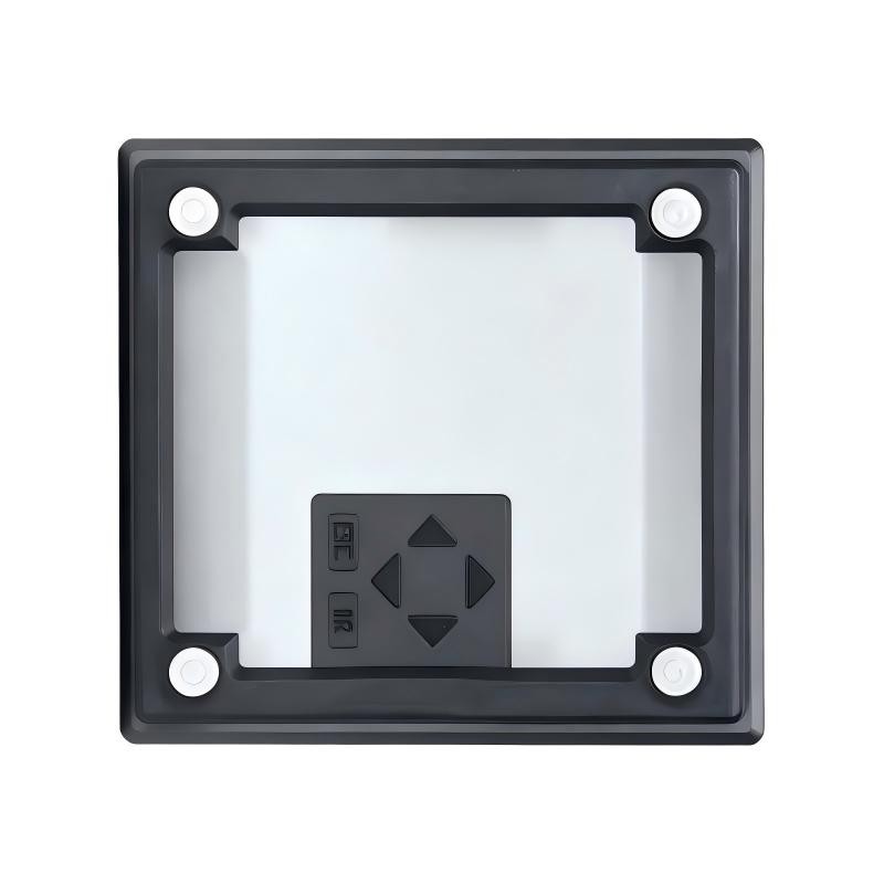
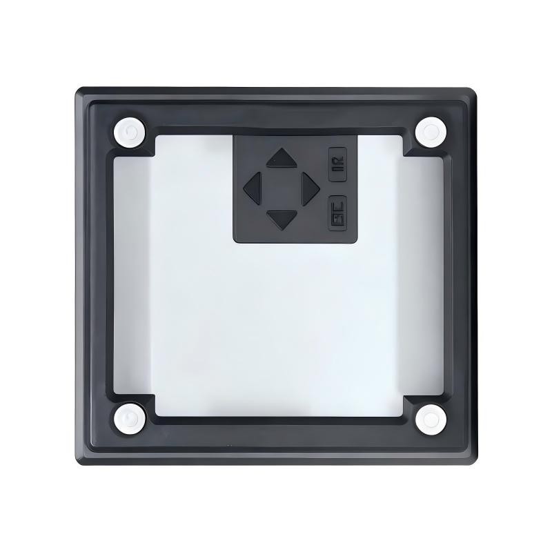
- 3500/22M Standard Transient Data Interface
- USA
- 241.3 × 24.4 × 241.8 mm
- 0.91 kg
- Xiamen, China
- New & In Stock
- T/T, PayPal, Western Union
- 1 Year
- 1-3 Working Days
- DHL, UPS, TNT, FedEx and EMS.
- 24-Hour Service
- COO
- 14
Our advantage

Global Logistics
We have a 10-year logistics and express cooperation agreement, so our products can be shipped to any place in the world.

Brand new and original
Our products are imported in bulk from the place of origin. Because of the cooperative relationship, our products are all original and 100% new.

24-hour service
We provide 7*24 hours service to our customers. We will be there whenever you need us.

Price advantage
All our products are priced very favorably because we have our own warehouse and supply.
| Company Information | |||
| [email protected] | |||
| Mobile | +8615980777398 | ||
| +8615980777398 | |||
| 15980777398 |
Product Overview
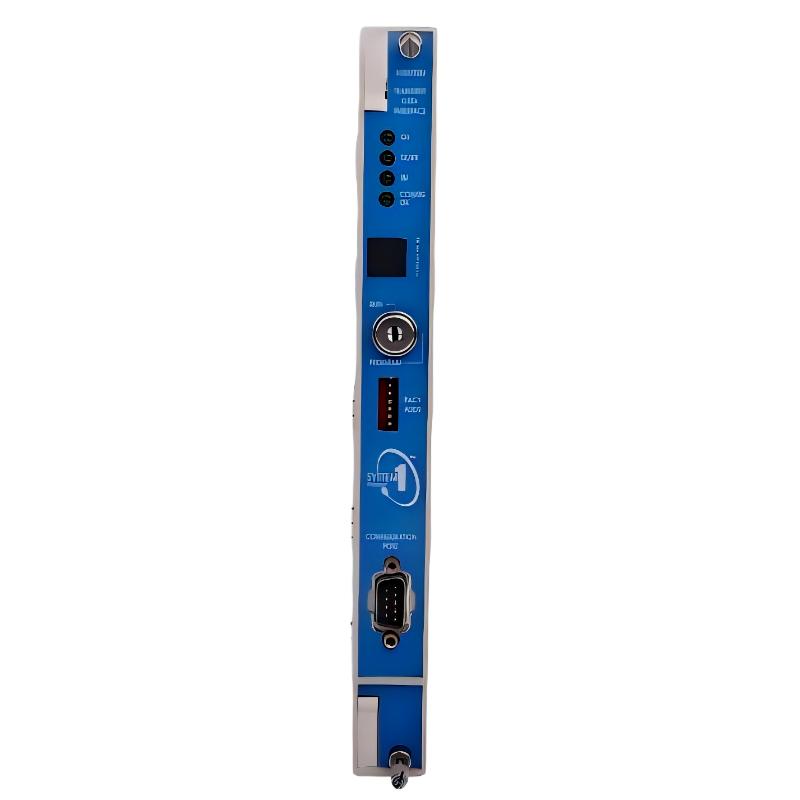
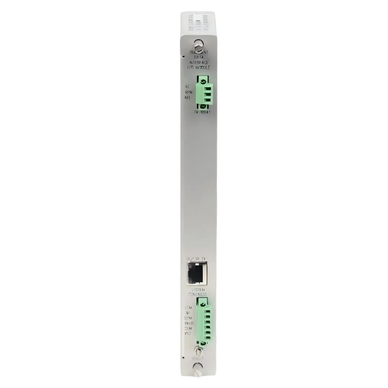
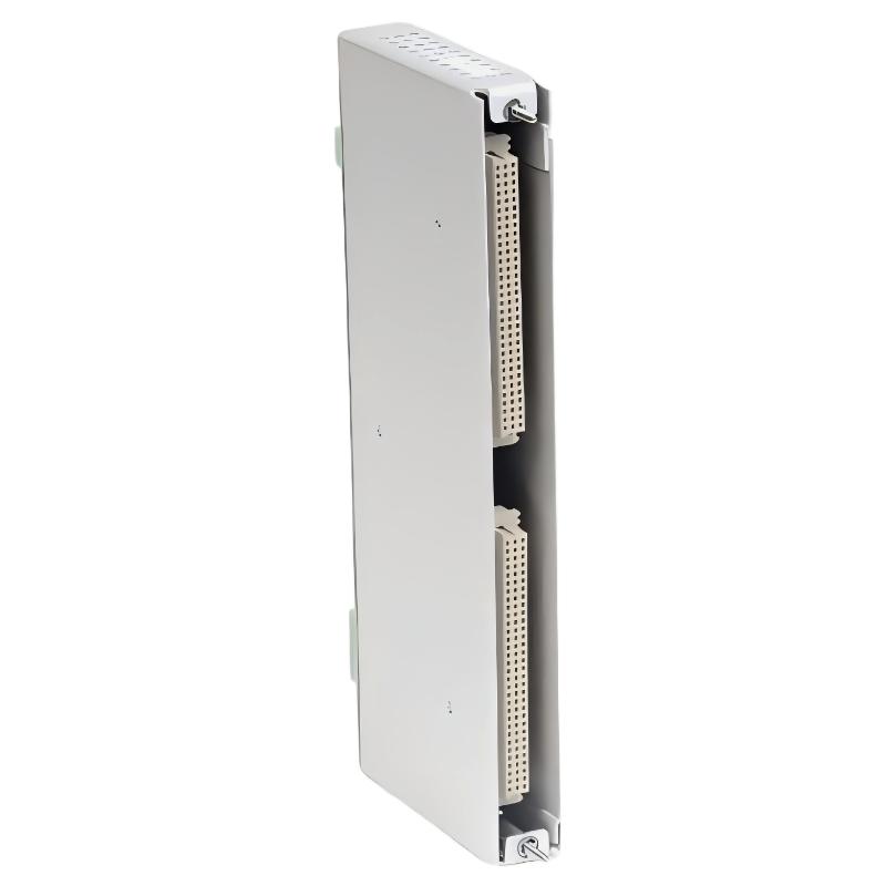
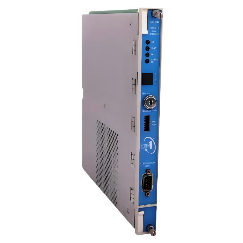
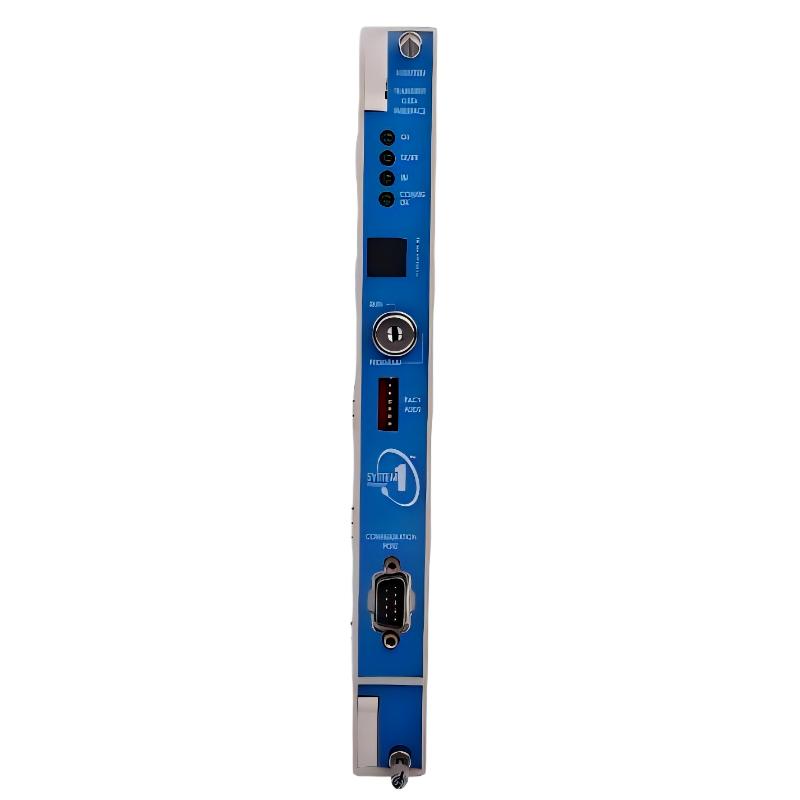
The Bently Nevada 288055-01+146031-01 is a standard Transient Data Interface (TDI) configuration for the 3500 Machinery Protection System. It combines the 288055-01 Standard Transient Data Interface Module with the 146031-01 10Base-T/100Base-TX Ethernet I/O Module. The assembly connects the 3500 rack with compatible machinery monitoring and configuration software, allowing operating data to be collected and transferred to an external computer system.
The TDI occupies the dedicated interface position in a 3500 rack, adjacent to the power supplies. It combines functions associated with the rack interface module with data collection and communication capabilities. This allows the rack to exchange information with compatible software without requiring a separate communication processor for those functions.
In rotating machinery installations, the 3500 system receives signals from monitoring modules connected to vibration, position, speed, and other machinery sensors. The TDI collects supported steady-state measurements and transfers the data through an Ethernet connection. With the appropriate dynamic data enabling configuration, it can also support waveform collection for more detailed machinery condition analysis.
For example, a plant operating centrifugal compressors may use the 3500 rack to monitor shaft vibration, bearing condition, and other mechanical operating parameters. The TDI provides the communication path through which compatible monitoring software can retrieve measurements, review historical behavior, and investigate changes associated with a developing machinery problem.
The 288055-01 module includes a USB configuration connection, while the 146031-01 I/O module provides copper Ethernet connectivity through a 10Base-T/100Base-TX interface. This configuration suits installations using standard Ethernet network cabling rather than the fiber-optic interface provided by the alternative 146031-02 module.
The TDI also provides rack-level functions through its front-panel controls and status indicators. These include a rack reset button, an address switch, operating-status LEDs, and a key-operated configuration mode selector. The available indications help maintenance personnel distinguish normal operation from communication, configuration, or rack-status problems.
One important distinction is that the TDI is not itself a vibration measurement module. It does not replace the monitoring modules that receive sensor signals, and it is not part of the critical machinery protection measurement path. Its primary responsibility is rack interfacing, data collection, and communication. The 3500 rack’s monitoring and protection functions remain dependent on the appropriate monitoring modules and system configuration.
The 288055-01+146031-01 configuration is therefore suited to installations that need standard 3500 rack communication, data collection, and copper Ethernet connectivity for compatible machinery monitoring software.
Technical Specifications
| Parameter | Specification |
|---|---|
| Manufacturer | Bently Nevada |
| Product Configuration | 288055-01 + 146031-01 |
| Product Series | 3500 Series |
| Product Type | Standard Transient Data Interface |
| Main Module | 288055-01 Standard TDI Module |
| I/O Module | 146031-01 10Base-T/100Base-TX Ethernet I/O Module |
| Interface Type | Standard |
| Ethernet Interface | 10Base-T / 100Base-TX |
| Ethernet Connection | RJ-45 |
| USB Configuration Port | USB-B |
| Host Communication | Ethernet TCP/IP |
| Primary Function | Rack interfacing, machinery data collection, and communication |
| Data Collection | Steady-state measurements and supported dynamic data |
| Dynamic Data Capability | Supported with the appropriate Channel Enabling Disk configuration |
| Rack Position | Dedicated full-height front slot adjacent to the power supplies |
| Front-Panel Controls | Rack reset button, address switch, keylock |
| Status Indication | OK, TX/RX, TM, and CONFIG OK LEDs |
| Power Consumption | 10.5 W |
| TDI Module Dimensions | 241.3 × 24.4 × 241.8 mm |
| TDI Module Weight | 0.91 kg |
| Shipping Weight | 3 kg |
Product Features
- Standard TDI configuration: Combines the 288055-01 interface module with the 146031-01 Ethernet I/O module.
- 3500 rack integration: Occupies the dedicated interface position adjacent to the rack power supplies.
- Copper Ethernet communication: Supports 10Base-T and 100Base-TX connections through the Ethernet I/O module.
- USB configuration interface: Provides a local connection for compatible configuration and data-retrieval tasks.
- Steady-state data collection: Retrieves supported measurements from compatible monitoring modules.
- Dynamic waveform capability: Supports waveform collection when the appropriate data-enabling configuration is installed.
- Rack address selection: Allows the rack address to be configured using the front-panel address switch.
- Front-panel diagnostics: Uses status LEDs to indicate operating, communication, and configuration conditions.
- Rack reset function: Provides a local reset control for specified rack-level conditions.
- Configuration access control: Includes a keylock for selecting RUN or PROGRAM mode.
- Monitoring software connectivity: Provides the communication path to compatible machinery condition-monitoring and configuration software.
Working Principle
The 3500/22M TDI collects supported information from monitoring modules installed in the 3500 rack and makes that information available to compatible host software. The 288055-01 performs the interface and data-collection functions, while the 146031-01 provides the copper Ethernet connection.
3500 Monitoring Modules → 288055-01 TDI → 146031-01 Ethernet I/O Module → Ethernet Network → Host Software
During normal operation, the monitoring modules process signals from their associated sensors and maintain the measurements required by the machinery protection system. The TDI communicates with compatible modules in the rack and collects available steady-state values, including measurements reported by the monitors.
The collected information can include supported static measurements such as overall vibration values and other monitored parameters. The TDI transfers the information through the Ethernet interface to compatible software, where engineers can review operating conditions, compare measurements, and investigate changes over time.
Static data collection is part of the standard TDI functionality. Dynamic waveform collection depends on the installed Channel Enabling Disk configuration and the enabled data capacity. When the required capability is available, the TDI can collect waveform data for supported channels, including data associated with transient machine conditions.
Waveform information is particularly useful when an overall vibration value does not fully explain a change in machine behavior. Engineers may examine waveform and spectrum data to investigate vibration patterns, shaft behavior, and other characteristics that require more detailed analysis. The actual measurements available depend on the installed monitoring modules, enabled channels, and system configuration.
The 146031-01 I/O module provides a 10Base-T/100Base-TX Ethernet interface. Its RJ-45 connection supports the copper network link between the rack and compatible host equipment. Network configuration, addressing, and access arrangements must be consistent with the plant’s monitoring network design.
The TDI also provides local controls and status information. The address switch sets the rack address, while the keylock determines whether the rack is in RUN or PROGRAM mode. RUN mode supports normal operation while restricting configuration changes; PROGRAM mode permits the supported local or remote configuration activities. The status LEDs help identify whether the module is operating correctly, communicating with other modules, and working with a valid rack configuration.
The rack reset button clears specified latched rack alarms and the Timed OK Channel Defeat condition. It should be used in accordance with the system operating procedure rather than as a substitute for diagnosing the underlying fault.
Although the TDI performs important communication and data collection functions, it is not part of the critical measurement path used for automatic machinery protection. A communication fault can affect access to data and configuration functions without necessarily stopping the rack’s normal monitoring and protection operation.
When commissioning the assembly, technicians should verify module seating, rack addressing, Ethernet connectivity, software communication, and the expected status indications. If waveform collection is required, the enabled channel capacity must also match the intended monitoring application.
Role in the Machinery Monitoring Architecture
The Bently Nevada 288055-01+146031-01 provides the interface between the 3500 rack and external monitoring software. It collects supported data from the rack and transfers it through a copper Ethernet connection for remote viewing, analysis, and configuration.
Machinery Sensors → 3500 Monitoring Modules → TDI → Ethernet Network → Condition Monitoring Software
| System Component | Function |
|---|---|
| 288055-01 TDI Module | Interfaces with the 3500 rack and collects supported monitoring data |
| 146031-01 Ethernet I/O Module | Provides the 10Base-T/100Base-TX copper Ethernet connection |
| 3500 Monitoring Modules | Process signals from connected machinery sensors |
| Proximity Probes | Measure relative shaft position and vibration in compatible installations |
| Seismic Vibration Sensors | Measure casing or structural vibration where supported |
| Speed and Phase Reference Sensors | Provide rotational speed or reference signals to compatible monitoring modules |
| 3500 Rack Power Supplies | Supply operating power to the rack modules |
| Ethernet Network | Carries data between the rack interface and compatible host equipment |
| System 1 Software | Supports machinery condition monitoring and diagnostic analysis |
| 3500 Configuration Software | Supports configuration of the compatible monitoring system |
| Plant Monitoring Computer | Hosts the applicable monitoring and configuration applications |
The TDI provides data access and communication rather than replacing the measurement and protection functions of the other rack modules. The selected Ethernet connection and software configuration must match the intended monitoring architecture.
Industrial Applications
| Application | Typical Use |
|---|---|
| Centrifugal Compressor Monitoring | Transfers supported vibration and operating measurements from the 3500 rack to monitoring software |
| Steam Turbine Monitoring | Provides rack communication for compatible machinery condition-monitoring systems |
| Gas Turbine Installations | Supports data collection from installed monitoring modules |
| Power Generation Facilities | Connects machinery protection racks with compatible monitoring and diagnostic software |
| Industrial Pump Monitoring | Makes supported shaft and vibration measurements available for review |
| Refinery Machinery | Supports data collection for rotating equipment operating in process plants |
| Petrochemical Facilities | Connects 3500 monitoring racks to the plant’s machinery diagnostic environment |
| Offshore Machinery Systems | Provides rack communication in compatible monitoring installations |
| Plant Maintenance Systems | Supports retrieval of operating measurements for condition assessment |
| Machinery Diagnostic Workstations | Transfers supported rack data to compatible analysis software |
Installation and Maintenance
- Verify the module configuration: Confirm that the assembly consists of the 288055-01 Standard TDI Module and the 146031-01 copper Ethernet I/O module.
- Prepare the rack position: Identify the dedicated TDI slot adjacent to the power supplies and confirm that the rack is configured for the intended interface module.
- Check rack compatibility: Confirm that the installed monitoring modules and rack configuration support the selected TDI arrangement.
- Install the modules correctly: Follow the applicable rack installation procedure and ensure that the TDI and its I/O module occupy their intended positions.
- Set the rack address: Configure the address switch according to the plant’s monitoring network and rack identification plan.
- Connect the Ethernet interface: Use a compatible copper Ethernet cable and verify that the RJ-45 connection is secure.
- Connect the configuration interface: Use the specified USB connection when carrying out supported local configuration or data-retrieval tasks.
- Set the operating mode: Use the keylock to select RUN or PROGRAM mode according to the required operating and configuration activity.
- Check status indicators: Review the OK, TX/RX, TM, and CONFIG OK LEDs to assess module operation, communication, and configuration status.
- Verify host communication: Confirm that compatible software can identify the rack and retrieve the expected monitoring data.
- Test required data collection: Check steady-state values and, where enabled, confirm that the required dynamic waveform channels can be collected.
- Document the configuration: Record module references, rack address, Ethernet settings, enabled data capacity, software configuration, and commissioning results.
If the TDI does not communicate with the host software, check the rack address, Ethernet cabling, network configuration, module seating, and status indications. If steady-state data is available but waveform data is missing, review the installed data-enabling configuration and the enabled channel capacity.
Related Components
| Component | Function |
|---|---|
| Bently Nevada 288055-01 | Standard 3500/22M TDI module supplied with a USB cable |
| Bently Nevada 146031-01 | 10Base-T/100Base-TX copper Ethernet I/O module |
| Bently Nevada 146031-02 | Alternative 100Base-FX fiber-optic Ethernet I/O module |
| Bently Nevada 3500/40M | Proximitor Monitor for compatible proximity transducer measurements |
| Bently Nevada 3500/42M | Proximity Seismic Monitor for supported vibration and position measurements |
| Bently Nevada 3500/20 Rack Interface Module | Related rack interface component used in compatible 3500 configurations |
| Bently Nevada 3500/09 Dynamic Data Enabling Disk | Enables configured steady-state and transient waveform data capacity |
| Bently Nevada 161580 | 3500/22M TDI operation and maintenance manual reference |
| Bently Nevada 164466 | Network accessories documentation reference |
| Ethernet Cable | Provides the copper network connection to compatible host equipment |
Recommended Related Models
| Model / Product Family | Product Type | Typical Application |
|---|---|---|
| Bently Nevada 288055-01 | Standard Transient Data Interface Module | Standard TDI module supplied with USB cable |
| Bently Nevada 146031-01 | 10Base-T/100Base-TX Ethernet I/O Module | Copper Ethernet connectivity for the 3500/22M TDI |
| Bently Nevada 146031-02 | 100Base-FX Ethernet I/O Module | Fiber-optic Ethernet connectivity for compatible TDI configurations |
| Bently Nevada 288055-02 | TMR Transient Data Interface Module | Triple Modular Redundant monitoring configurations |
| Bently Nevada 3500/22M | Transient Data Interface | Rack-level data collection and communication |
| Bently Nevada 3500 Series | Machinery Protection System | Monitoring and protection of compatible rotating machinery |
Key Advantages
- Combines the standard TDI module and copper Ethernet I/O module in one configuration.
- Connects the 3500 rack with compatible machinery monitoring and configuration software.
- Collects supported steady-state measurements and configured dynamic data.
- Provides front-panel controls and status indicators for rack operation and diagnosis.
- Supports copper Ethernet communication through the 146031-01 I/O module.
- Operates as the rack interface without replacing the critical machinery protection measurement path.
Technical FAQs
What is the difference between the 288055-01 and 146031-01?
The 288055-01 is the Standard Transient Data Interface Module, responsible for rack interfacing and supported data collection. The 146031-01 is the 10Base-T/100Base-TX Ethernet I/O Module, which provides the copper Ethernet connection. The two references identify different parts of the complete 3500/22M configuration.
Does the standard TDI configuration automatically provide all transient waveform data?
No. Steady-state data collection is standard, while dynamic and transient waveform collection depends on the appropriate Channel Enabling Disk configuration and the enabled channel capacity. The available data functions must match the monitoring requirements of the installed system.
Can the 146031-01 be replaced with a fiber-optic Ethernet I/O module?
The 146031-02 is the corresponding 100Base-FX fiber-optic I/O option for compatible TDI configurations. A change from copper to fiber requires the correct I/O module, compatible network cabling and connectors, and a suitable network arrangement.
Does a TDI communication fault automatically disable machinery protection?
The TDI is not part of the critical monitoring path for automatic machinery protection. A communication problem can interrupt data retrieval or software access, but it does not automatically mean that the rack’s normal monitoring and protection functions have stopped. The rack’s actual status and fault indications should be evaluated separately.