

ProductPRODUCT
Featured products
Contact Us
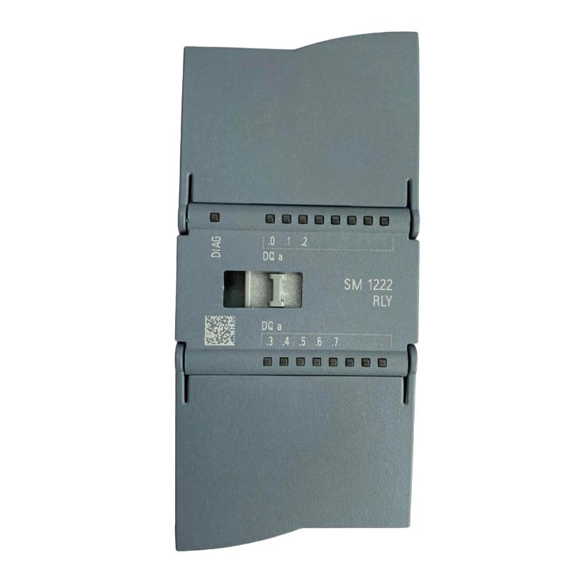
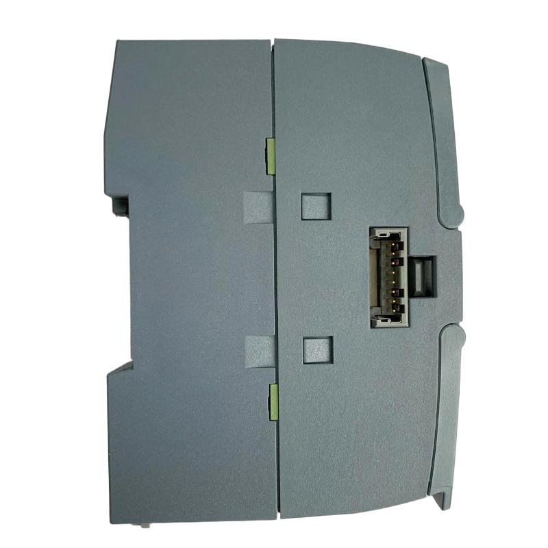
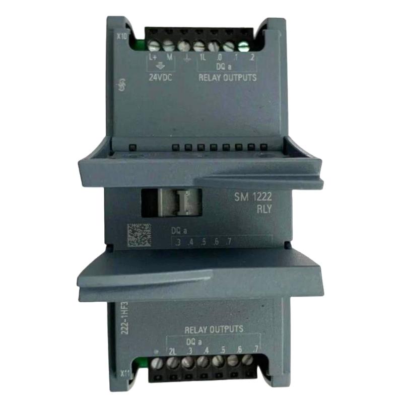
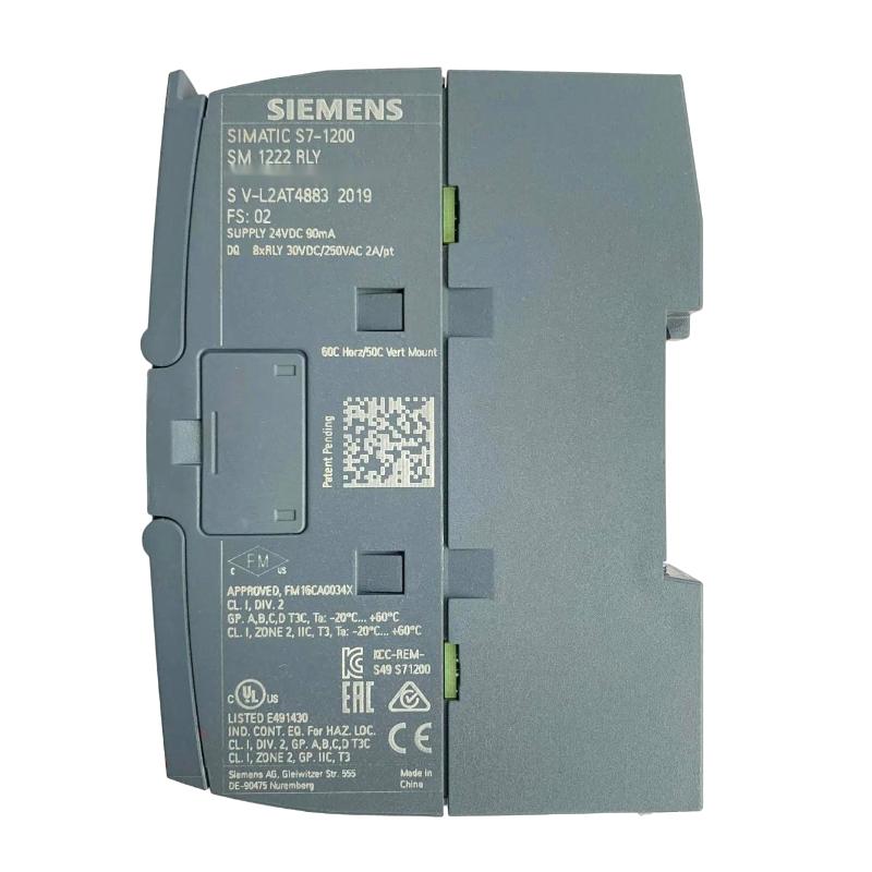
- Siemens
- 6AG2222-1HF32-1XB0
- Digital Output Module
- Germany
- 45 × 100 × 75 mm
- 0.19 kg
- Xiamen, China
- New & In Stock
- T/T, PayPal, Western Union
- 1 Year
- 1-3 Working Days
- DHL, UPS, TNT, FedEx and EMS.
- 24-Hour Service
- COO
- 7
Our advantage

Global Logistics
We have a 10-year logistics and express cooperation agreement, so our products can be shipped to any place in the world.

Brand new and original
Our products are imported in bulk from the place of origin. Because of the cooperative relationship, our products are all original and 100% new.

24-hour service
We provide 7*24 hours service to our customers. We will be there whenever you need us.

Price advantage
All our products are priced very favorably because we have our own warehouse and supply.
| Company Information | |||
| [email protected] | |||
| Mobile | +8615980777398 | ||
| +8615980777398 | |||
| 15980777398 |
Product Overview
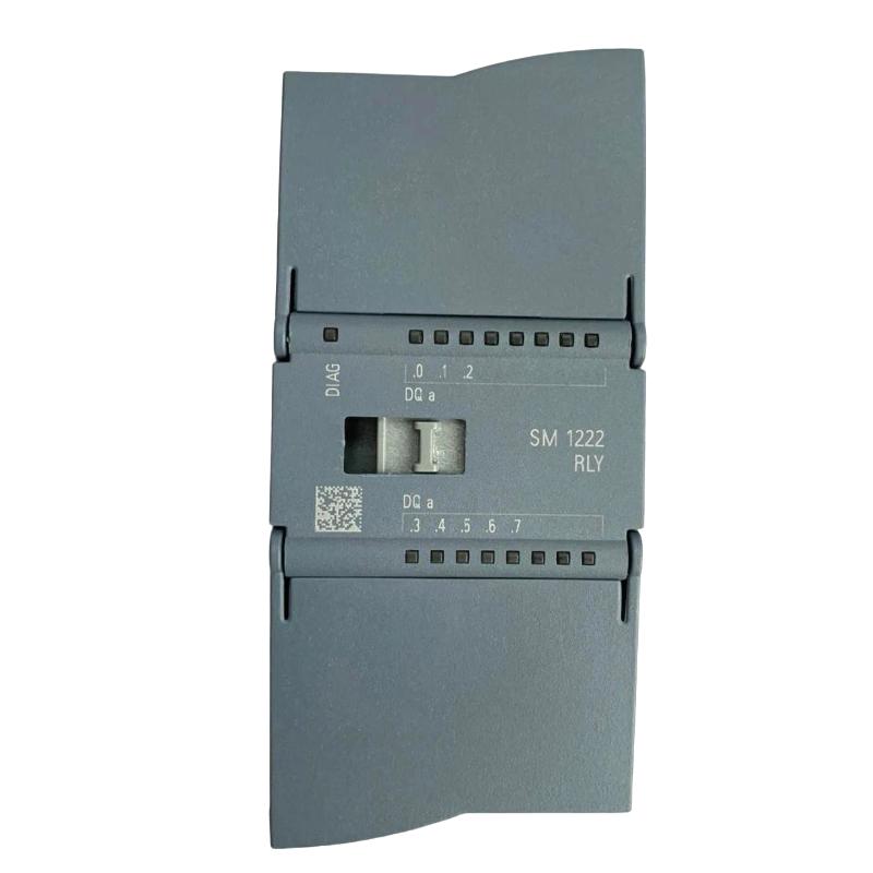
The Siemens 6AG2222-1HF32-1XB0 is a SIPLUS S7-1200 SM 1222 8DQ RLY RAIL digital output module designed to switch external electrical circuits through eight relay output channels. Based on the standard 6ES7222-1HF32-0XB0, this module extends the output capabilities of a compatible SIMATIC S7-1200 PLC while incorporating conformal coating for specified demanding environmental conditions, including railway-related applications.
Unlike transistor-output modules, the 6AG2222-1HF32-1XB0 uses mechanical relay contacts. Its outputs can switch compatible DC circuits from 5 to 30 V DC and AC circuits from 5 to 250 V AC, subject to the specified contact ratings and load characteristics. This makes the module suitable for applications where different voltage types or electrical isolation between control and load circuits are required.
Each of the eight relay outputs supports a rated switching current of up to 2 A. Typical applications include operating interface circuits, switching indicator devices, controlling auxiliary equipment, and enabling external contactors. The module can also handle suitable resistive loads directly when their voltage, current, and power requirements remain within the permitted limits.
The relay outputs are arranged in two-channel groups, which is important when planning wiring and electrical isolation. The module does not provide integrated short-circuit protection, so appropriate external protective devices must be included in the installation. Inductive loads also require careful consideration of contact ratings, switching frequency, and suppression arrangements.
The SIPLUS RAIL configuration is intended for installations that require specified environmental performance and conformal coating. It can be used in railway-related equipment and industrial control cabinets when the operating environment, electrical design, and system configuration meet the applicable requirements.
Technical Specifications
| Parameter | Specification |
|---|---|
| Manufacturer | Siemens |
| Product Type | SIPLUS S7-1200 SM 1222 8DQ RLY RAIL Digital Output Module |
| Model | 6AG2222-1HF32-1XB0 |
| Product Family | SIPLUS S7-1200 |
| Module Type | SM 1222 Digital Output Module |
| Standard Base Model | 6ES7222-1HF32-0XB0 |
| Number of Digital Outputs | 8 |
| Output Type | Relay |
| Number of Output Groups | 4 groups of 2 outputs |
| Rated Relay Coil Supply Voltage | 24 V DC |
| Permissible Supply Voltage | 20.4–28.8 V DC |
| Rated Switching Current | 2 A per output |
| Rated Switching Voltage, DC | 5–30 V DC |
| Rated Switching Voltage, AC | 5–250 V AC |
| Maximum Resistive Load Current | 2 A |
| Maximum Lamp Load | 30 W DC / 200 W AC |
| Maximum Total Output Current per Group | 10 A under specified horizontal-installation conditions up to 50 °C |
| Switching Delay, OFF to ON | Maximum 10 ms with resistive load |
| Switching Delay, ON to OFF | Maximum 10 ms with resistive load |
| Short-Circuit Protection | Not integrated; external protection required |
| Relay Mechanical Life | Up to 10 million operating cycles under specified conditions |
| Electrical Life | Up to 100,000 operating cycles at rated load voltage, subject to specified conditions |
| Backplane Bus Current at 5 V DC | Maximum 120 mA |
| Typical Power Loss | 4.5 W |
| Diagnostic Functions | Diagnostic information and diagnostic alarms |
| Required Front Connector | Yes |
| Protection Rating | IP20 |
| Conformal Coating | Yes |
| Railway Environmental Requirements | Designed for specified railway-related requirements, subject to applicable conditions |
| Operating Temperature | -25 to +60 °C; up to +70 °C for 10 minutes under specified conditions |
| Dimensions | 45 × 100 × 75 mm |
| Weight | 0.19 kg |
Product Features
- Eight relay output channels: Provides eight independently controlled switching outputs for compatible external circuits.
- AC and DC switching: Supports specified AC and DC loads within the relay contact ratings.
- 2 A rated switching current: Allows each output to switch loads within its permitted current and voltage limits.
- Mechanical contact isolation: Uses relay contacts to separate the switched load circuit from the relay-control side according to the specified isolation arrangement.
- Grouped output architecture: Organizes the eight channels into four groups of two, which must be considered during electrical design.
- Flexible load interfacing: Can switch suitable control circuits directly or operate external interface devices.
- Diagnostic support: Provides diagnostic information for system monitoring and troubleshooting.
- External circuit protection: Requires appropriate protective devices because short-circuit protection is not integrated.
- Conformal coating: Protects coated electronic assemblies under specified environmental conditions.
- Railway-oriented design: Supports applications meeting the applicable environmental and railway-related requirements.
Working Principle
The 6AG2222-1HF32-1XB0 converts output commands from a SIMATIC S7-1200 CPU into relay contact switching actions. The CPU executes the user program and updates the output data. The module then energizes or de-energizes the corresponding relay coil, changing the state of the associated contacts.
A typical operating sequence follows this path:
PLC Program → CPU Output Data → SM 1222 Relay Coil → Relay Contacts → External Load
When a control program issues an ON command, the relevant relay coil is energized through the module’s internal circuitry. The relay contacts change state and complete or interrupt the external circuit according to the wiring arrangement. When the command is removed, the relay returns to its unenergized state, subject to the specified switching characteristics.
The module provides eight relay outputs arranged in four groups of two. Each output has a rated switching current of 2 A, but the current rating alone does not determine whether a load can be switched safely. The voltage, load type, inrush current, power consumption, and switching frequency must also be checked. The permitted load characteristics differ between resistive, inductive, and lamp loads.
The relay contacts support specified DC voltages from 5 to 30 V and AC voltages from 5 to 250 V. This flexibility is useful when a PLC must operate different types of auxiliary circuits. However, the voltage and current ratings must be observed together, and the installation must follow the applicable contact-load specifications.
Relay switching is generally slower than transistor switching because it involves mechanical contact movement. The specified switching delay with resistive loads is up to 10 ms in both the OFF-to-ON and ON-to-OFF directions. Mechanical contacts also wear over time, particularly when switching loads with high inrush currents or inductive characteristics. Applications with frequent switching should therefore account for relay life and maintenance requirements.
Short-circuit protection is not integrated into the module. External circuit protection must be selected to suit the connected loads and wiring. For inductive loads such as contactor coils and solenoid valves, appropriate suppression may reduce contact stress and electrical transients. The protection method must be compatible with the load voltage and the circuit design.
The module communicates with the CPU through the S7-1200 system backplane. Once the hardware configuration and output addresses are assigned in the engineering project, the controller can use the module to execute programmed switching sequences, interlocks, alarms, and equipment-control functions.
The SIPLUS RAIL version incorporates conformal coating and specified environmental capabilities. These features support operation under defined conditions but do not replace appropriate enclosure protection, wiring practices, or external electrical safeguards.
Role in the SIMATIC S7-1200 Control Architecture
The 6AG2222-1HF32-1XB0 serves as a relay-based output expansion module in a compatible SIMATIC S7-1200 automation system. It receives commands from the CPU and switches connected electrical circuits, allowing the controller to operate equipment that requires relay contacts rather than transistor outputs.
Field Sensors → S7-1200 CPU → SM 1222 Relay Output Module → External Control Circuits → Actuators
| System Component | Function |
|---|---|
| SIMATIC S7-1200 CPU | Executes the control program and generates output commands |
| 6AG2222-1HF32-1XB0 | Provides eight relay output channels |
| System Backplane | Transfers output data between the CPU and module |
| 24 V DC Power Supply | Supplies the module’s relay coils and compatible control circuits |
| Interface Relays | Provide additional switching capacity or electrical interfacing where required |
| Contactors | Switch suitable motor and power circuits |
| Solenoid Valves | Operate compatible pneumatic or hydraulic equipment |
| Indicator Devices | Display operating conditions and control states |
| Digital Input Modules | Return equipment status and feedback signals to the CPU |
| HMI Panel | Displays process states, alarms, and operating information |
| Engineering Software | Supports hardware configuration, output assignment, and diagnostics |
The module performs relay switching rather than independent control logic. The CPU determines when each output should operate, while external protection and switching devices handle requirements that exceed the module’s contact ratings.
Industrial Applications
| Application | Typical Use |
|---|---|
| Railway Automation | Switching compatible auxiliary circuits in installations meeting specified railway requirements |
| Rolling Stock Equipment | Controlling auxiliary devices and status indicators |
| Transportation Infrastructure | Operating compatible equipment interfaces and control circuits |
| Machine Automation | Switching relay-controlled functions and auxiliary equipment |
| Pump and Fan Systems | Controlling suitable contactor coils and auxiliary circuits |
| Industrial Control Cabinets | Adding relay-based outputs to a compact PLC system |
| Material Handling | Operating compatible diverters, stops, and auxiliary mechanisms |
| Building and Facility Equipment | Switching suitable AC or DC control loads within the specified ratings |
| Equipment Signaling | Operating indicators and annunciation circuits |
| Distributed Automation | Providing relay outputs for a local S7-1200 control subsystem |
Application suitability depends on the load voltage, current, switching frequency, contact life, output-group loading, and environmental conditions. Loads outside the module’s permitted switching capacity require suitable external switching equipment.
Installation and Maintenance
- Verify the order number: Confirm that the module is 6AG2222-1HF32-1XB0 and that the application requires the SM 1222 8DQ RLY RAIL configuration.
- Check CPU compatibility: Verify that the selected SIMATIC S7-1200 CPU and hardware configuration support the module.
- Isolate all relevant power sources: Follow the site’s lockout procedure before installation, wiring changes, or module replacement.
- Verify load voltage: Confirm that each switched circuit falls within the specified 5–30 V DC or 5–250 V AC contact-voltage range.
- Check contact current and load type: Keep each output within the 2 A rating and verify the applicable limits for resistive, inductive, and lamp loads.
- Calculate output-group loading: Check the total current for each group of two outputs and comply with the applicable group-current and temperature limits.
- Install external circuit protection: Provide suitable short-circuit and overcurrent protection because the module has no integrated short-circuit protection.
- Review inductive-load suppression: Check contactor coils, solenoids, and other inductive loads for suitable suppression and transient-control arrangements.
- Inspect the front connector: Ensure that the required connector is installed correctly and that the conductors are securely terminated.
- Verify output addresses: Match each relay channel to the appropriate hardware address, control-program assignment, and electrical drawing.
- Check the operating environment: Confirm that the temperature, mounting arrangement, cabinet protection, and railway-related conditions meet the module’s specifications.
- Perform functional tests: Test each output with its connected circuit, verify the switching sequence and diagnostic information, and confirm that the equipment responds correctly before returning it to service.
When an output fails to switch a load, check the CPU command, output address, relay-coil supply, connector wiring, external protection, and load circuit. If the relay operates but the external device does not, investigate the switched circuit and load before replacing the module.
Compatible System Components
The 6AG2222-1HF32-1XB0 is intended for use within a compatible SIMATIC S7-1200 system. Associated components should match the CPU’s supported expansion configuration and the electrical requirements of the relay-controlled loads.
| Component | Function |
|---|---|
| Compatible SIMATIC S7-1200 CPU | Executes the control program and generates output commands |
| Required S7-1200 Front Connector | Provides the module’s electrical connections |
| 24 V DC Power Supply | Supplies the relay coils and compatible control circuits |
| Interface Relays | Provide additional switching or circuit interfacing when required |
| Contactors | Switch compatible motor and power circuits |
| Solenoid Valves | Operate suitable pneumatic or hydraulic functions |
| Indicator Lamps | Display machine status and operating conditions |
| Digital Input Modules | Acquire feedback and equipment-status signals |
| SIMATIC HMI Panels | Display process information and diagnostic messages |
| PROFINET Network Components | Connect the CPU with compatible automation equipment |
| STEP 7 in TIA Portal | Supports module configuration, output addressing, and troubleshooting |
Recommended Related Models
| Model | Product Type | Relevance |
|---|---|---|
| Siemens 6ES7222-1HF32-0XB0 | SIMATIC S7-1200 SM 1222 8DQ RLY Digital Output Module | Standard module on which the SIPLUS RAIL variant is based |
| Siemens 6AG2222-1BF32-1XB0 | SIPLUS S7-1200 SM 1222 8DQ Digital Output Module | Related transistor-output version for compatible 24 V DC switching applications |
| Siemens 6ES7222-1BH32-0XB0 | SIMATIC S7-1200 SM 1222 16DQ Digital Output Module | Standard 16-channel transistor-output option |
| Siemens 6AG2221-1BF32-1XB0 | SIPLUS S7-1200 SM 1221 8DI RAIL Digital Input Module | Related RAIL module for acquiring field feedback |
| Siemens 6AG2223-1PL32-1XB0 | SIPLUS S7-1200 SM 1223 Digital Input/Output Module | Related RAIL combination module with relay outputs |
| Siemens 6AG2214-1AG40-1XB0 | SIPLUS S7-1200 CPU 1214C DC/DC/DC RAIL | Related RAIL CPU for controller and expansion-module integration |
Key Advantages
- Provides eight relay output channels for compatible AC and DC circuits.
- Supports switching voltages up to 250 V AC or 30 V DC within the specified contact ratings.
- Offers a 2 A rated switching current per output.
- Allows relay-based control of loads that are unsuitable for direct transistor-output switching.
- Incorporates conformal coating for specified railway-related environmental conditions.
Technical FAQs
Can the 6AG2222-1HF32-1XB0 switch both AC and DC loads?
Yes. Its relay contacts are specified for 5–250 V AC and 5–30 V DC. The permitted current and load capacity depend on the voltage and load characteristics, so the 2 A rating should not be treated as a universal rating for every application.
How does the four-group output arrangement affect wiring?
The eight outputs are arranged in four groups of two. Engineers should account for the grouping when planning circuit connections, electrical separation, and total current. The applicable wiring diagrams and group-current limits must be followed.
Why is this relay module preferable to the transistor-output version in some applications?
The relay version supports specified AC loads as well as DC loads and provides mechanical contacts. It can be useful where the application requires relay-based switching. However, relay contacts have mechanical wear and slower switching response than transistor outputs, so frequent-switching applications may favor a suitable transistor module.
What should be checked if a relay output operates intermittently?
Inspect the relay-coil supply, terminal connections, external wiring, load inrush current, protective devices, and contact condition. Also check whether the load exceeds the permitted switching capacity or whether frequent switching has accelerated contact wear. Compare the actual load characteristics with the module’s ratings before replacing the output module.