

ProductPRODUCT
Featured products
Contact Us
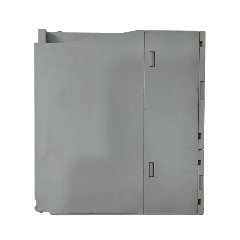
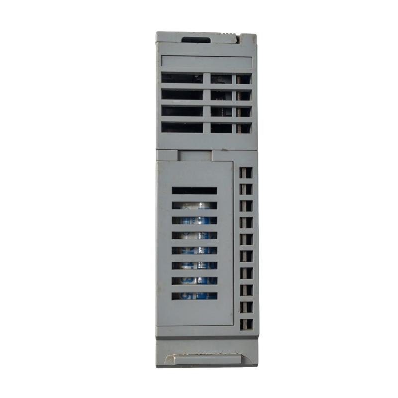
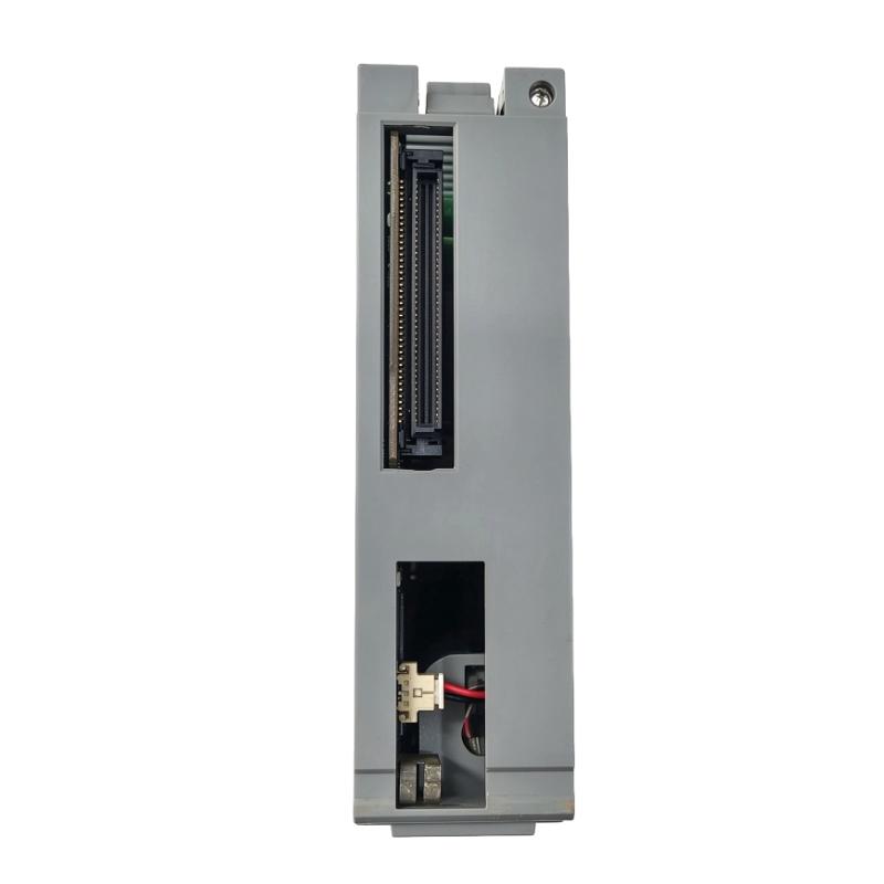
- Honeywell
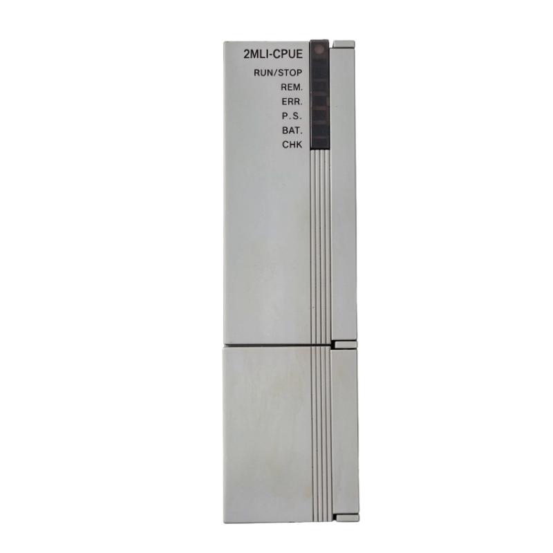
- 2MLI-CPUE
- CPU Module
- USA
- 120 × 25 × 110 mm
- 0.13 kg
- Xiamen, China
- New & In Stock
- T/T, PayPal, Western Union
- 1 Year
- 1-3 Working Days
- DHL, UPS, TNT, FedEx and EMS.
- 24-Hour Service
- COO
- 6
Our advantage

Global Logistics
We have a 10-year logistics and express cooperation agreement, so our products can be shipped to any place in the world.

Brand new and original
Our products are imported in bulk from the place of origin. Because of the cooperative relationship, our products are all original and 100% new.

24-hour service
We provide 7*24 hours service to our customers. We will be there whenever you need us.

Price advantage
All our products are priced very favorably because we have our own warehouse and supply.
| Company Information | |||
| [email protected] | |||
| Mobile | +8615980777398 | ||
| +8615980777398 | |||
| 15980777398 |
Product Overview
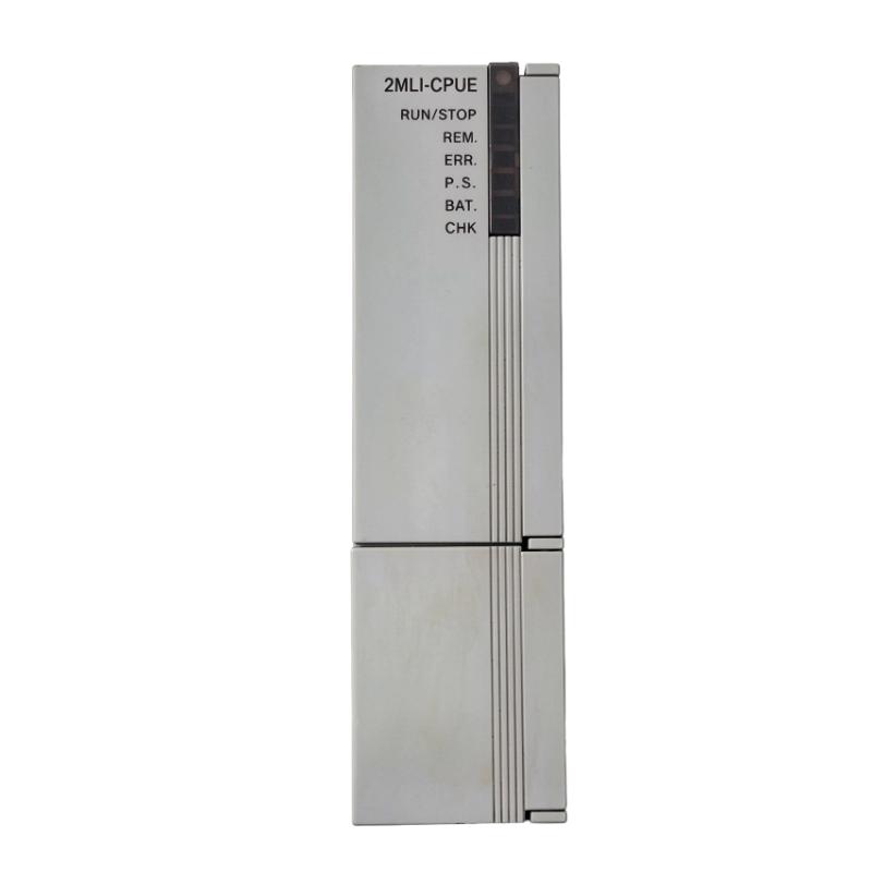
The Honeywell 2MLI-CPUE MasterLogic-200 CPU Module is identified as a central processing unit module for the MasterLogic-200 programmable logic controller platform. A PLC CPU coordinates program execution, manages input and output data, processes control conditions, and determines the commands required by connected automation equipment.
In a typical industrial control system, the CPU receives process information from digital and analog input modules, evaluates the programmed logic, and updates the corresponding output commands. These operations support sequential machine control, equipment interlocking, process monitoring, and coordinated operation across multiple I/O modules.
The MasterLogic-200 platform supports modular system configurations with different CPU performance levels, I/O capacities, communication options, and redundancy arrangements. Selecting the correct CPU therefore requires more than matching the series name. The exact model designation, supported base configuration, program capacity, communication interfaces, and existing system architecture must all be considered.
For maintenance and replacement projects, engineers should verify the installed CPU model against the system configuration before transferring programs or reconnecting the controller. CPU variants within the same family may differ in processing capability, supported I/O capacity, and hardware configuration. The exact specifications of the 2MLI-CPUE should be confirmed before applying configuration data from another MasterLogic-200 CPU.
Technical Specifications
| Parameter | Specification |
|---|---|
| Manufacturer | Honeywell |
| Product Type | MasterLogic-200 CPU Module |
| Model | 2MLI-CPUE |
| Product Series | MasterLogic-200 |
| Module Type | Programmable Logic Controller CPU Module |
| Dimensions | 120 × 25 × 110 mm |
| Weight | 0.13 kg |
Product Features
- Centralized control processing: Executes the PLC program and coordinates control operations across the configured automation system.
- Input and output management: Processes information exchanged with compatible digital, analog, and special-function I/O modules.
- Sequential control: Supports programmed operating sequences, interlocks, and equipment coordination within the PLC application.
- Modular system architecture: Fits the general MasterLogic-200 approach of combining a CPU with separately selected I/O and system components.
- Program-based operation: Uses application logic to determine how process conditions affect equipment commands.
- System integration: Supports integration into an appropriately configured industrial automation system.
- Maintenance-oriented identification: The complete CPU model designation helps engineers distinguish the installed unit during troubleshooting and replacement.
- Configuration-dependent scalability: The available I/O capacity and system functions depend on the exact CPU variant and supported hardware arrangement.
Working Principle
The CPU module is the processing center of a programmable logic controller. It executes the stored control program and coordinates the flow of information between input modules, internal program variables, and output modules.
The basic control sequence is:
Field Sensors → Input Modules → CPU Program Execution → Output Modules → Controlled Equipment
Input modules acquire field signals such as equipment status, process measurements, and operator commands. The CPU evaluates these values against the logic and operating conditions defined in the application program. It then updates output data to control connected equipment.
For sequential machinery, the program may use permissives, timers, counters, and interlocks to determine when an operation can proceed. In process-control applications, the CPU may evaluate temperature, pressure, level, or flow measurements and calculate the required response through compatible output modules.
The CPU also coordinates communication and data exchange according to the capabilities of the installed hardware and configured network. Depending on the application, this may involve communication with engineering software, operator interfaces, remote equipment, or other controllers.
During commissioning, the correct CPU configuration is essential. The installed hardware, I/O assignments, program version, and communication settings must agree with the actual system. A mismatch can prevent normal startup, cause I/O configuration errors, or interrupt communication with connected equipment.
The detailed processing speed, memory capacity, supported instruction set, and maximum I/O configuration must be checked against the exact CPU model. Specifications published for the 2MLI-CPUS, 2MLI-CPUH, or 2MLI-CPUU should not automatically be attributed to the 2MLI-CPUE.
Role in the MasterLogic-200 Control Architecture
The CPU coordinates the operation of the MasterLogic-200 control system. It receives data from configured input modules, executes the control application, and distributes commands to output modules and other supported system components.
A typical architecture is:
Field Instruments → Input Modules → MasterLogic-200 CPU → Output Modules → Actuators and Control Equipment
| System Component | Function |
|---|---|
| CPU Module | Executes the control program and coordinates system operation |
| Digital Input Modules | Acquire discrete equipment status and contact signals |
| Digital Output Modules | Operate compatible relays, solenoids, and other discrete loads |
| Analog Input Modules | Acquire process variables from compatible transmitters |
| Analog Output Modules | Send analog control signals to compatible field devices |
| RTD Input Modules | Acquire temperature measurements from resistance temperature detectors |
| Thermocouple Input Modules | Convert thermocouple signals into temperature data |
| High-Speed Counter Modules | Acquire and count high-frequency pulse signals |
| Event Input Modules | Record selected digital input changes for sequence-of-events analysis |
| PLC Base and Backplane | Provide mounting and electrical interconnection for compatible modules |
| Engineering Software | Supports programming, configuration, monitoring, and troubleshooting |
The exact arrangement depends on the selected CPU variant, the installed base, and the required I/O configuration. Before integrating a replacement CPU, engineers should verify the supported hardware combination and confirm that the application program matches the intended controller.
Industrial Applications
| Application | Typical Use |
|---|---|
| Manufacturing Automation | Coordinating machine sequences and production equipment |
| Process Automation | Executing logic associated with process measurements and operating conditions |
| Packaging Machinery | Managing machine cycles, interlocks, and discrete control operations |
| Material Handling | Coordinating conveyor equipment and transfer sequences |
| Water Treatment | Processing instrument signals and controlling treatment equipment |
| Pumping Systems | Managing pump commands, operating permissives, and equipment status |
| HVAC Automation | Coordinating compatible heating, ventilation, and equipment-control functions |
| Industrial Utilities | Supervising auxiliary equipment through configured PLC logic |
| Production Lines | Coordinating multiple machines and monitoring operational states |
| Equipment Modernization | Replacing or maintaining a CPU within a verified compatible MasterLogic-200 installation |
Application suitability depends on the actual CPU variant, the required processing performance, I/O capacity, communication interfaces, and the control program. Existing system requirements should be documented before selecting a replacement controller.
Installation and Maintenance
- Verify the model designation: Confirm the complete CPU part number on the installed unit and compare it with the intended replacement before proceeding.
- Check hardware compatibility: Verify that the CPU is supported by the existing MasterLogic-200 base, power arrangement, and installed system components.
- Back up the application program: Preserve the existing PLC program, configuration data, and relevant documentation before replacing or reconfiguring the controller.
- Record communication settings: Document the configured network parameters, communication interfaces, and connections used by the existing system.
- Inspect the installation environment: Check the cabinet for excessive dust, moisture, corrosive contaminants, and conditions that could affect electronic equipment.
- Follow electrical safety procedures: Isolate the equipment as required and follow the applicable installation instructions before removing or inserting the CPU.
- Check the power arrangement: Confirm that the installed power module and distribution arrangement meet the requirements of the exact CPU and system configuration.
- Verify I/O assignments: Compare the installed I/O modules and their addresses with the project configuration before starting the controller.
- Check program compatibility: Confirm that the application program and configuration are suitable for the exact CPU model rather than assuming that all family variants are interchangeable.
- Inspect module connections: Check the CPU seating, base connections, and applicable communication connections before restoring operation.
- Perform controlled startup tests: Verify CPU status indications, communication, I/O operation, interlocks, and representative control sequences before returning the equipment to normal operation.
- Document maintenance results: Record the installed model, program version, configuration changes, startup results, and any corrective actions taken.
Always follow the applicable Honeywell installation and commissioning procedures. If the CPU fails to start or communicate, check the power supply, hardware configuration, program compatibility, and communication settings before concluding that the controller is defective.
Compatible System Components
The MasterLogic-200 platform uses a modular architecture that combines a CPU with appropriate power, base, I/O, and communication components. Compatibility with the specific 2MLI-CPUE designation must be verified before these components are selected for an installation.
| Component | Function |
|---|---|
| Honeywell MasterLogic-200 CPU Variants | Execute PLC programs according to the selected controller configuration |
| Honeywell 2MLI-D21A | Eight-point 24 V DC digital input module |
| Honeywell 2MLF-DV4A | Four-channel analog voltage output module |
| Honeywell 2MLF-DV8A | Eight-channel analog voltage output module |
| Honeywell 2MLF-RD4A | Four-channel RTD input module |
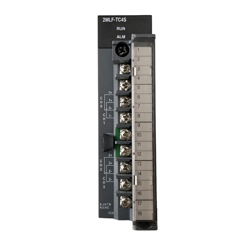
| Honeywell 2MLF-TC4S | Four-channel thermocouple input module |
| Honeywell 2MLF-HD2A | Differential-input high-speed counter module |
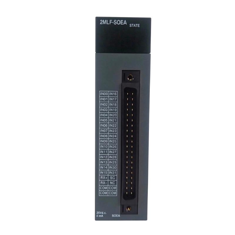
| Honeywell 2MLF-SOEA | Sequence-of-events input module |
| MasterLogic-200 Power Supply | Supplies power to the compatible controller system |
| MasterLogic-200 Main and Expansion Bases | Provide mounting and interconnection for supported modules |
| Compatible Communication Modules | Provide supported network or serial communication functions |
| PLC Engineering Software | Supports program development, configuration, and diagnostics |
Recommended Related Models
| Model | Product Type | Relevance |
|---|---|---|
| Honeywell 2MLI-CPUS | MasterLogic-200 Standard CPU Module | Standard-performance CPU option within the family |
| Honeywell 2MLI-CPUH | MasterLogic-200 High-Performance CPU Module | Higher-performance non-redundant CPU option |
| Honeywell 2MLI-CPUU | MasterLogic-200 Enhanced CPU Module | Enhanced non-redundant CPU option |
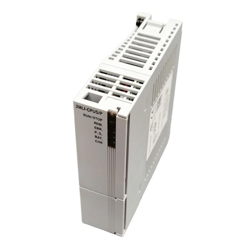
| Honeywell 2MLI-CPUS/P | MasterLogic-200 Standard CPU Module with Redundant Power | Standard CPU configuration with redundant power |
| Honeywell 2MLR-CPUH/T | MasterLogic-200 Redundant CPU Module | Redundant controller option using TP/CAT5 communication |
| Honeywell 2MLR-CPUH/F | MasterLogic-200 Redundant CPU Module | Redundant controller option using fiber-optic communication |
Key Advantages
- Centralizes PLC program execution and equipment-control logic.
- Coordinates data exchange between compatible input and output modules.
- Supports sequential control, interlocking, and process automation.
- Forms the processing center of a modular MasterLogic-200 system.
- Allows the control application to be organized around configured I/O and communication functions.
- Provides a defined CPU model identity for maintenance and system configuration work.
Technical FAQs
What should be verified before replacing a 2MLI-CPUE CPU module?
Confirm the complete model number, supported base and power configuration, I/O arrangement, program compatibility, and communication settings. The CPUE designation should be checked against the actual installed hardware before selecting another CPU model as a substitute.
Can a 2MLI-CPUS or 2MLI-CPUU be used as a direct replacement?
Not without a compatibility review. The MasterLogic-200 CPU variants have different documented performance and configuration characteristics. Verify program support, memory requirements, I/O capacity, hardware connections, and the intended system architecture before substituting another model.
What information should be backed up before CPU replacement?
Preserve the application program, hardware and I/O configuration, communication parameters, relevant system settings, and maintenance records. After replacement, verify that the restored configuration matches the installed hardware before allowing the controller to operate connected equipment.
What should be investigated if the CPU does not communicate with the engineering workstation?
Check the communication interface, cable and connection condition, configured communication parameters, controller operating status, and software compatibility. Also verify that the installed CPU model supports the selected communication method before investigating a possible hardware fault.