

ProductPRODUCT
Featured products
Contact Us
- Siemens
- 6AG2193-6BP20-4DC0
- BaseUnit
- Germany
- 20 × 117 × 35 mm
- 0.047 kg
- Xiamen, China
- New & In Stock
- T/T, PayPal, Western Union
- 1 Year
- 1-3 Working Days
- DHL, UPS, TNT, FedEx and EMS.
- 24-Hour Service
- COO
- 5
Our advantage

Global Logistics
We have a 10-year logistics and express cooperation agreement, so our products can be shipped to any place in the world.

Brand new and original
Our products are imported in bulk from the place of origin. Because of the cooperative relationship, our products are all original and 100% new.

24-hour service
We provide 7*24 hours service to our customers. We will be there whenever you need us.

Price advantage
All our products are priced very favorably because we have our own warehouse and supply.
| Company Information | |||
| [email protected] | |||
| Mobile | +8615980777398 | ||
| +8615980777398 | |||
| 15980777398 |
Product Overview
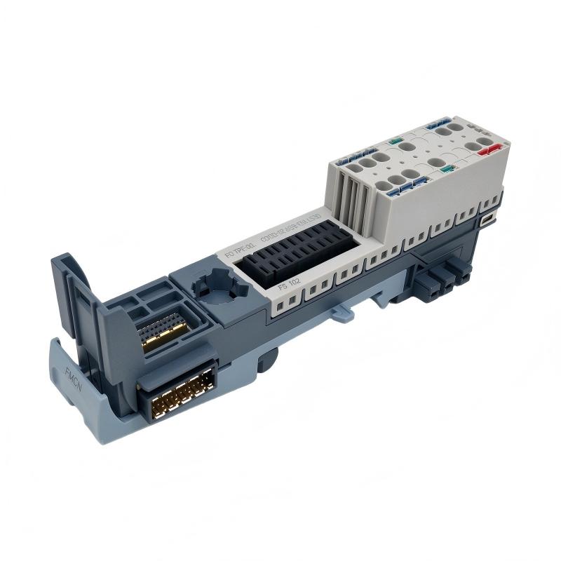
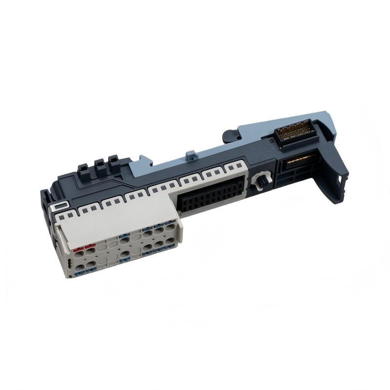
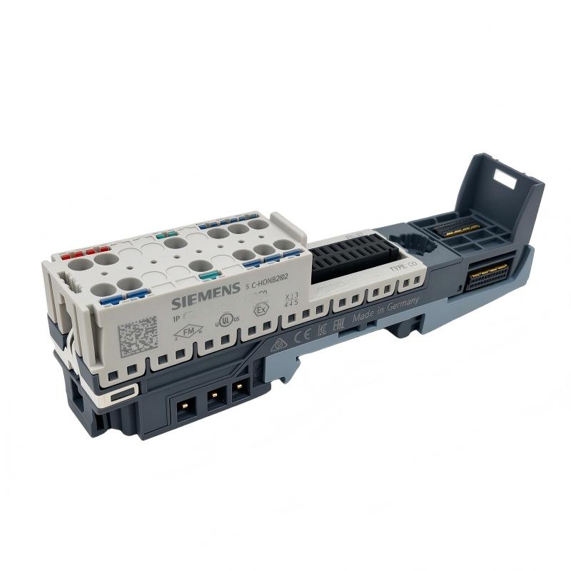
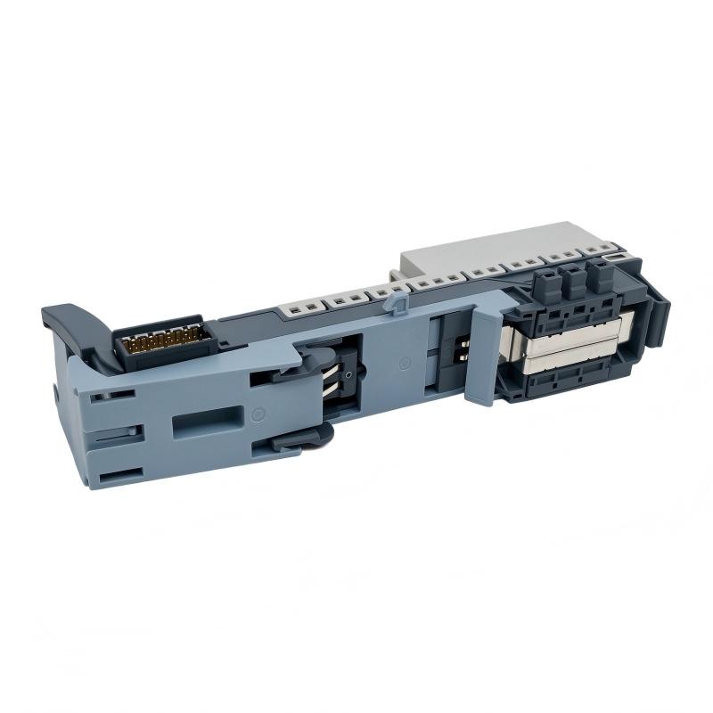
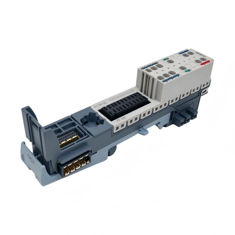
The Siemens 6AG2193-6BP20-4DC0 is a SIPLUS ET 200SP BaseUnit used to connect a compatible electronic module to field wiring and the station’s power distribution system. Its configuration, BU20-P6+A2+4D TX RAIL, type C0, provides six process terminals and two AUX terminals. It is intended for applications where a new load group must be established within a distributed I/O station.
This BaseUnit is suitable for control cabinets in railway-related and industrial automation systems where field connections and power distribution need to be organized into separate groups. The electronic module installed on the BaseUnit performs the actual input acquisition or output switching, while the BaseUnit provides the electrical connection points and supports the required potential arrangement.
The C0 configuration differs from BaseUnits with more process terminals or without AUX connections. Its six process terminals accommodate the connection arrangement required by the selected electronic module, while the two AUX terminals provide connections for the designated auxiliary potential. These features should be considered when designing a station with limited terminal requirements or when adding a new load group to an existing ET 200SP installation.
As a SIPLUS RAIL product, the 6AG2193-6BP20-4DC0 incorporates conformal coating and specified environmental capabilities for demanding operating conditions. Its suitability depends on the electronic module, electrical loads, potential-group design, mounting orientation, and environmental requirements of the installation.
Technical Specifications
| Parameter | Specification |
|---|---|
| Manufacturer | Siemens |
| Product Type | SIPLUS ET 200SP BaseUnit |
| Model | 6AG2193-6BP20-4DC0 |
| Product Family | SIPLUS ET 200SP |
| Product Designation | BU20-P6+A2+4D TX RAIL |
| BaseUnit Type | BU type C0 |
| Standard BaseUnit Reference | 6ES7193-6BP20-0DC0 |
| Terminal Type | Push-in |
| Number of Process Terminals | 6 |
| Number of AUX Terminals | 2 |
| Load Group Arrangement | Starts a new load group |
| P1 and P2 Bus Supply | 24 V DC |
| AUX Bus Supply | 24 V DC |
| Maximum Current-Carrying Capacity | 10 A |
| AUX Potential Arrangement | Equal potential group to P1/P2 bus or PE, according to the system configuration |
| Conformal Coating | Yes |
| Operating Temperature, Horizontal Installation | -40 to +70 °C; +85 °C for 10 minutes under specified OT4 and ST1/ST2 conditions |
| Operating Temperature, Vertical Installation | -40 to +50 °C |
| Railway Application Standards | Includes applicable EN 50121, EN 50124, EN 50125, EN 50155, and EN 45545-2 requirements, subject to specified conditions |
| Dimensions | 20 × 117 × 35 mm |
| Weight | 0.047 kg |
Product Features
- BU type C0 configuration: Provides a specific terminal arrangement for compatible ET 200SP electronic modules.
- Six process terminals: Supports the field connections required by the installed module.
- Two AUX terminals: Provides connections for the designated auxiliary potential.
- New load-group configuration: Allows a separate electrical group to be established within the ET 200SP station.
- Push-in terminal technology: Simplifies field wiring and routine maintenance.
- 24 V DC bus connections: Supports the specified P1/P2 and AUX supply arrangement.
- Conformal coating: Protects coated assemblies under the specified environmental conditions.
- Railway-oriented environmental capability: Supports installations that meet the applicable temperature, vibration, shock, and electromagnetic compatibility requirements.
- Modular station integration: Works with compatible ET 200SP electronic modules as part of a distributed automation system.
Working Principle
The 6AG2193-6BP20-4DC0 acts as the electrical connection interface for a compatible ET 200SP electronic module. Field conductors connect to the BaseUnit’s push-in terminals, while the electronic module performs the actual signal-processing function. The BaseUnit does not independently execute control logic or replace the functions of the installed I/O module.
A typical signal path is:
PLC or Controller → ET 200SP Interface Module → Backplane Bus → I/O Module → BaseUnit Terminals → Field Devices
In a digital input application, a sensor or contact supplies a signal through the field wiring to the installed input module. In a digital output application, the output module switches the assigned circuit and routes the resulting electrical state to the connected actuator. The specific behavior depends on the electronic module and the configured I/O channel.
The C0 configuration provides six process terminals and two AUX terminals. This arrangement is relevant when the station requires a smaller number of process connections alongside auxiliary wiring. The terminal assignment must match the selected electronic module and the station’s wiring diagram.
A defining feature of this model is its ability to start a new load group. In a distributed I/O station, load groups help organize electrical supply distribution between different sections of the installation. When this BaseUnit establishes a new group, the power connections and protective devices must be arranged according to the intended circuit design. It should not be substituted for a BaseUnit intended to continue an existing load group without checking the electrical consequences.
The P1/P2 and AUX bus connections support the designated supply arrangement. Engineers must verify the intended potentials and ensure that the connected circuits remain within the BaseUnit’s specified current-carrying capacity. The exact wiring depends on the installed module and the station’s power-distribution design.
The SIPLUS version incorporates conformal coating for specified environmental conditions. In railway-related installations, correct mounting, wiring, enclosure protection, and compliance with the applicable operating limits remain necessary for the complete system.
Role in the SIMATIC ET 200SP Control Architecture
Within the SIMATIC ET 200SP architecture, the 6AG2193-6BP20-4DC0 provides the terminal interface and electrical distribution arrangement for a compatible I/O module. Its C0 configuration supports six process connections, two AUX connections, and the establishment of a new load group.
SIMATIC PLC → ET 200SP Interface Module → Backplane Bus → I/O Module → BaseUnit → Field Circuits
| System Component | Function |
|---|---|
| SIMATIC PLC or Controller | Executes the automation program and processes I/O data |
| ET 200SP Interface Module | Connects the distributed I/O station to the controller network |
| 6AG2193-6BP20-4DC0 BaseUnit | Provides six process terminals, two AUX terminals, and a new-load-group arrangement |
| Compatible ET 200SP I/O Module | Acquires input signals or switches output circuits |
| P1 and P2 Power Buses | Distributes the designated supply potentials through the station |
| AUX Bus | Provides the specified auxiliary connection |
| 24 V DC Power Supply | Supplies the required voltage for compatible control and field circuits |
| Field Sensors | Supply measurement or status signals to input modules |
| Field Actuators | Respond to commands issued through compatible output modules |
The electronic module determines the signal-processing function, while the BaseUnit establishes the terminal and potential connections. Correct operation depends on the compatibility of both components and the station’s electrical configuration.
Industrial Applications
| Application | Typical Use |
|---|---|
| Railway Automation | Connecting compatible I/O modules in railway-related control systems |
| Rolling Stock Control Cabinets | Organizing sensor and actuator connections within distributed I/O stations |
| Transportation Infrastructure | Supporting monitoring and control equipment |
| Industrial Control Panels | Establishing a new load group in an ET 200SP station |
| Machine Automation | Connecting field circuits through compatible electronic modules |
| Process Monitoring | Routing sensor and status signals through distributed I/O |
| Auxiliary Control Circuits | Providing process and AUX connections within the specified electrical arrangement |
| Equipment Exposed to Environmental Stress | Supporting installations that meet the applicable SIPLUS operating conditions |
The appropriate application depends on the installed I/O module, the number and type of field connections, the power-distribution arrangement, and the actual environmental conditions.
Installation and Maintenance
- Verify the order number: Confirm that the component is 6AG2193-6BP20-4DC0 and that the required configuration is BU20-P6+A2+4D TX RAIL, type C0.
- Check electronic module compatibility: Ensure that the selected ET 200SP electronic module supports the C0 BaseUnit configuration.
- Isolate the electrical supply: Follow the site’s lockout procedure and disconnect the relevant power sources before installation or maintenance.
- Confirm the load-group position: Verify that the BaseUnit is intended to establish a new load group at the planned position in the station.
- Review the terminal assignment: Match the six process terminals to the installed module’s wiring diagram before connecting field conductors.
- Check the AUX connections: Confirm that the two AUX terminals are suitable for the intended auxiliary potential and are wired according to the system design.
- Inspect the mounting rail: Check the DIN rail and neighboring components for damage, contamination, or mechanical interference.
- Prepare the conductors: Use conductors and ferrules, where applicable, that comply with the push-in terminal requirements.
- Verify the supply distribution: Check the P1/P2 and AUX bus connections against the electrical drawings and confirm that the required potentials are correct.
- Inspect environmental conditions: Verify mounting orientation, ambient temperature, vibration exposure, and enclosure conditions against the applicable specifications.
- Check module seating and wiring: Ensure that the BaseUnit and electronic module are correctly installed and that all conductors are securely retained.
- Perform commissioning checks: Restore power under the approved procedure, verify the station configuration, and test the connected I/O channels and field devices.
When troubleshooting, check the field wiring, auxiliary connections, supply distribution, and installed electronic module before replacing the BaseUnit. A fault in a field device or power supply can produce symptoms similar to a terminal-interface problem.
Compatible System Components
The 6AG2193-6BP20-4DC0 is intended for use within the SIMATIC ET 200SP platform. Associated components must match the C0 terminal arrangement, new-load-group function, and electrical requirements of the connected circuits.
| Component | Function |
|---|---|
| Compatible ET 200SP I/O Modules | Process digital or analog signals through the BaseUnit interface |
| SIMATIC ET 200SP Interface Module | Connects the distributed station to the controller network |
| SIMATIC PLC | Executes automation logic and processes I/O data |
| 24 V DC Power Supply | Supplies the required control and field-circuit voltage |
| ET 200SP Power Distribution Components | Support the station’s supply and potential-group arrangement |
| DIN Rail | Provides the mechanical mounting structure |
| Compatible Push-In Conductors | Connect field circuits to the process and AUX terminals |
| Field Sensors | Supply measurement or status signals to compatible input modules |
| Field Actuators | Receive switching commands from compatible output modules |
| Auxiliary Circuit Wiring | Connects circuits to the designated AUX potential |
Recommended Related Models
| Model | Product Type | Relevance |
|---|---|---|
| Siemens 6ES7193-6BP20-0DC0 | SIMATIC ET 200SP BaseUnit | Standard BaseUnit reference for the C0 configuration |
| Siemens 6AG2193-6BP20-4BB1 | SIPLUS ET 200SP BaseUnit | Related B1 configuration with 12 process terminals and no AUX terminals |
| Siemens 6AG2193-6BP20-4BF0 | SIPLUS ET 200SP BaseUnit | Related F0 configuration with eight process terminals and four AUX terminals |
| Siemens 6AG2193-6BP20-4DA0 | SIPLUS ET 200SP BaseUnit | Related A0 configuration with 16 process terminals and 10 AUX terminals for a new load group |
| Siemens 6AG2193-6BP20-4BA0 | SIPLUS ET 200SP BaseUnit | Related A0 configuration with 16 process terminals and AUX connections for continuing a load group |
| Siemens 6AG2193-6BP00-4BD0 | SIPLUS ET 200SP BaseUnit | Related D0 configuration with 12 process terminals and no AUX terminals |
Key Advantages
- Six process terminals and two AUX terminals in a compact ET 200SP BaseUnit configuration.
- Supports the establishment of a new load group.
- Push-in connections simplify field wiring.
- Supports the designated P1/P2 and AUX potential arrangement.
- Conformal coating supports specified demanding industrial and railway-related environments.
Technical FAQs
When is the C0 BaseUnit configuration preferable to an F0 configuration?
The 6AG2193-6BP20-4DC0 provides six process terminals and two AUX terminals, whereas the F0 model 6AG2193-6BP20-4BF0 provides eight process terminals and four AUX terminals. The C0 configuration may be appropriate when the required terminal count is lower and its electrical arrangement matches the intended installation.
What must be checked before using the AUX terminals?
Verify the intended auxiliary potential, the relationship between the AUX bus and the P1/P2 bus or PE, and the station’s wiring diagram. The AUX terminals must be used according to the specified potential arrangement rather than treated as independent connections for arbitrary voltages.
How does the new-load-group function affect station expansion?
This BaseUnit is intended to start a new load group, so its position determines where a separate group begins in the station’s power-distribution arrangement. Confirm the intended supply boundary, protection, and connected loads before installing it as part of an expansion.
What environmental limits should be checked in a railway control cabinet?
For horizontal installation, the specified operating range is -40 to +70 °C, with +85 °C permitted for 10 minutes under specified OT4 and ST1/ST2 conditions. For vertical installation, the range is -40 to +50 °C. Vibration, shock, electromagnetic compatibility, and applicable railway requirements must also be assessed.