

ProductPRODUCT
Featured products



Contact Us
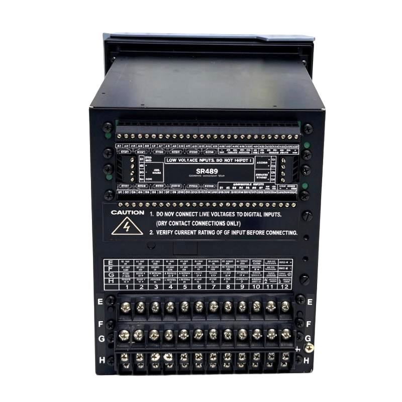
- GE
- 489-P5-HI-A20-T
- Generator Management Relay
- USA
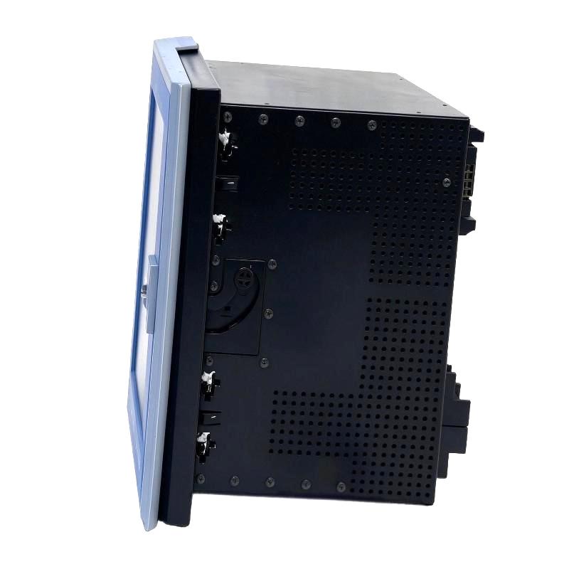
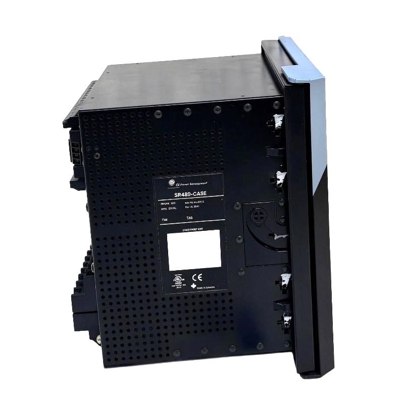
- 252 × 216 × 224 mm
- 7.7 kg
- Xiamen, China
- New & In Stock
- T/T, PayPal, Western Union
- 1 Year
- 1-3 Working Days
- DHL, UPS, TNT, FedEx and EMS.
- 24-Hour Service
- COO
- 8
Our advantage

Global Logistics
We have a 10-year logistics and express cooperation agreement, so our products can be shipped to any place in the world.

Brand new and original
Our products are imported in bulk from the place of origin. Because of the cooperative relationship, our products are all original and 100% new.

24-hour service
We provide 7*24 hours service to our customers. We will be there whenever you need us.

Price advantage
All our products are priced very favorably because we have our own warehouse and supply.
| Company Information | |||
| [email protected] | |||
| Mobile | +8615980777398 | ||
| +8615980777398 | |||
| 15980777398 |
Product Overview
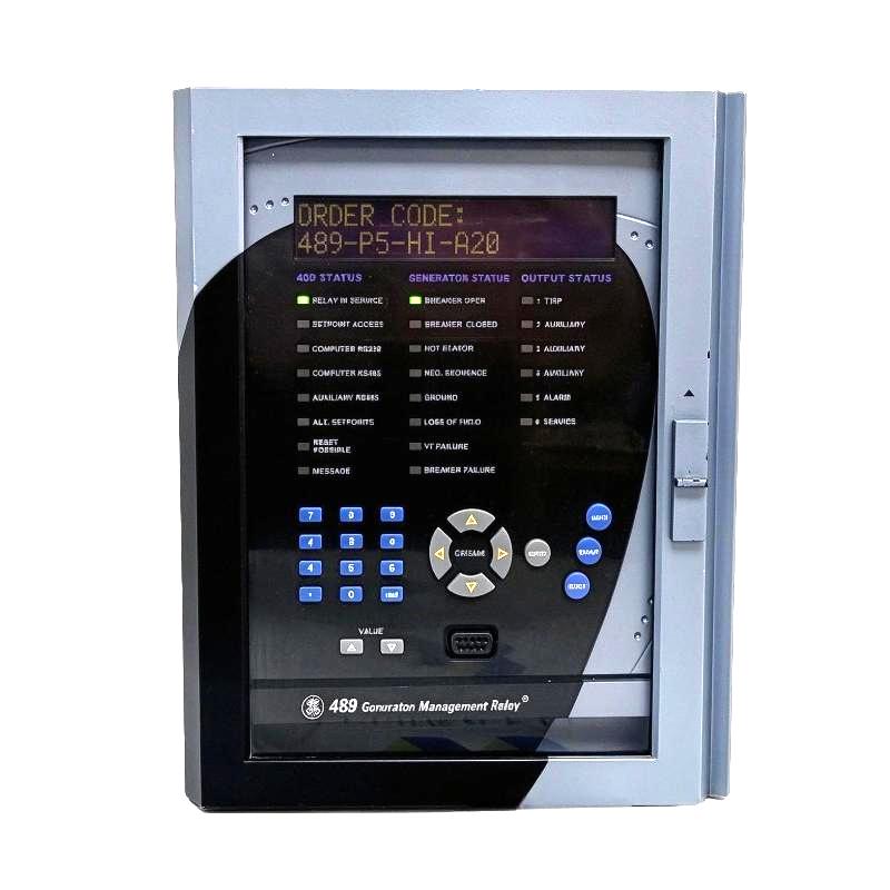
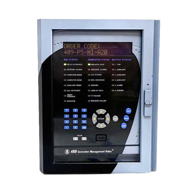
The GE Multilin 489-P5-HI-A20-T Generator Management Relay is used to protect and monitor synchronous generators in industrial power-generation systems. It combines generator protection, electrical measurement, thermal monitoring, and control logic in one relay. In a generator control panel, it evaluates electrical and operating conditions and initiates alarms or trip commands when configured protection limits are exceeded.
The P5 configuration accepts 5 A phase-current transformer secondary inputs, making current-transformer compatibility an important consideration during installation or replacement. The HI power-supply option supports a high-range auxiliary supply, while A20 specifies 4–20 mA analog outputs. The T enhancement adds an improved display and keypad along with a 10Base-T Ethernet port.
For a standby generator in a manufacturing plant, the relay can monitor electrical loading, detect abnormal current conditions, and supervise operating parameters such as voltage, frequency, and winding or bearing temperatures through the supported measurement inputs. If a configured protection condition occurs, the relay can operate its assigned trip output to initiate generator disconnection.
The 489 is more than an overcurrent relay. Its protection and monitoring functions allow engineers to coordinate electrical fault protection with generator thermal limits and operating conditions. The final configuration must reflect the generator’s rated data, current-transformer ratios, voltage-transformer ratios, cooling arrangement, and required trip logic.
The Ethernet interface is useful when the generator must exchange monitoring information with a supervisory system. Communication setup, analog-output assignments, protection settings, and breaker interlocks should all be verified as part of commissioning rather than treated as independent configuration tasks.
Technical Specifications
| Parameter | Specification |
|---|---|
| Manufacturer | GE |
| Product Family | Multilin 489 |
| Model | 489-P5-HI-A20-T |
| Product Type | Generator Management Relay |
| Phase Current Transformer Input | 5 A secondary |
| Auxiliary Power Supply | 90–300 V DC or 70–265 V AC at 48–62 Hz |
| Analog Outputs | 4–20 mA |
| Display | Enhanced display with larger LCD and improved keypad |
| Ethernet Interface | 10Base-T |
| Serial Communication | Front-panel RS232 and RS485 interfaces |
| Communication Protocols | Modbus RTU, Modbus TCP/IP, and DNP 3.0 Level 2, subject to interface and configuration |
| Generator Protection | Configurable electrical and thermal protection functions |
| RTD Inputs | Supports generator temperature monitoring through compatible RTDs |
| Digital Inputs | 9 opto-isolated inputs |
| Relay Outputs | Configurable protection, alarm, and auxiliary outputs |
| Size | 252 × 216 × 224 mm |
| Weight | 7.7 kg |
Product Features
- Generator-specific protection: Combines multiple electrical and thermal protection functions for generator applications.
- 5 A phase-current inputs: Matches installations using compatible 5 A current-transformer secondaries.
- Thermal monitoring: Supports temperature monitoring through compatible RTD inputs for generator windings and other monitored locations.
- Voltage and frequency supervision: Monitors electrical operating conditions relevant to generator protection and operation.
- Configurable analog outputs: Provides 4–20 mA signals for transferring selected measurements to compatible control or monitoring equipment.
- Ethernet connectivity: The T configuration adds a 10Base-T Ethernet interface for supported supervisory communication.
- Serial communication: RS232 and RS485 interfaces support configuration and data exchange through the corresponding supported functions.
- Programmable logic: Configurable logic and output assignments allow protection events to be incorporated into the generator control sequence.
- Event and disturbance information: Recorded operating information helps engineers investigate trips and abnormal generator behavior.
- Enhanced operator interface: The larger LCD and improved keypad support local access to measurements, settings, and status information.
Working Principle
The 489-P5-HI-A20-T receives electrical measurements from the generator’s current and voltage transformers, together with temperature signals from compatible RTDs and status information from configured digital inputs. The relay processes these inputs and compares them with the relevant protection settings.
A typical generator protection arrangement follows this sequence:
Generator CTs / VTs / RTDs → Multilin 489 → Protection Logic → Alarm or Trip Output → Generator Breaker / Shutdown Circuit
During normal operation, the relay monitors the generator’s electrical quantities and configured thermal conditions. If the measured current, voltage, frequency, temperature, or another supported protection quantity crosses its specified operating threshold, the relay evaluates the condition according to the applicable pickup level, timing characteristic, and logic configuration.
For example, if a generator develops an abnormal current condition, the corresponding protection element evaluates the measured current and determines whether the condition requires an alarm or trip. If the configured trip criteria are satisfied, the relay operates the assigned output connected to the generator breaker or shutdown circuit.
Temperature supervision adds another layer of protection. RTDs installed at selected generator locations provide temperature measurements that can be compared with configured limits. This allows the relay to respond to excessive temperature even when the electrical measurements alone do not fully describe the developing problem.
The relay also supports analog and digital communication functions. A selected measurement can be assigned to a 4–20 mA output for a compatible PLC analog input, while supported Ethernet or serial interfaces can transfer information to a supervisory system. These interfaces supplement the protection functions; they do not replace the physical trip circuit.
Proper operation depends on correct CT and VT ratios, appropriate generator settings, valid RTD wiring, and accurate output assignments. Engineers should verify these items before performing functional tests and returning the generator to service.
Role in a Generator Protection Architecture
The Multilin 489 sits between the generator measurement circuits and the equipment responsible for alarms, tripping, and supervisory monitoring. It evaluates operating conditions and applies the configured protection logic before issuing a control output.
Generator → CTs / VTs / RTDs → Multilin 489 → Trip and Alarm Circuits → Generator Breaker / Control System
| System Element | Function |
|---|---|
| Generator | Produces electrical power and supplies the quantities being monitored |
| Current Transformers | Provide phase-current signals to the relay |
| Voltage Transformers | Supply voltage measurements for applicable protection and monitoring functions |
| RTD Sensors | Monitor temperatures at configured generator locations |
| Multilin 489 | Processes measurements and executes generator protection logic |
| Generator Breaker | Disconnects the generator from the electrical system when commanded |
| Trip Circuit | Transfers the relay’s protection command to the breaker or shutdown system |
| Digital Inputs | Receive external status and control signals |
| Analog Outputs | Transfer selected measurements as 4–20 mA signals |
| Ethernet Network | Supports communication with compatible supervisory equipment |
| Serial Network | Supports configured RS232 or RS485 communication functions |
| Operator Interface | Displays measurements, alarms, and configuration information locally |
The relay’s settings must be coordinated with the generator’s ratings and the surrounding power system. Breaker control, shutdown interlocks, and any external protection devices should be tested as part of the complete protection scheme.
Industrial Applications
| Application | Typical Use |
|---|---|
| Industrial Generator Sets | Monitoring and protecting generators supplying production facilities |
| Standby Power Systems | Detecting abnormal operating conditions during backup power operation |
| Cogeneration Plants | Coordinating generator protection with plant electrical distribution |
| Utility-Connected Generators | Protecting generator equipment within a coordinated electrical protection scheme |
| Manufacturing Facilities | Monitoring generator loading and temperature in critical power systems |
| Power Plant Auxiliary Systems | Supervising generator operating conditions and associated alarm circuits |
| Generator Control Panels | Integrating electrical protection, measurement, and control signals |
| Generator Retrofit Projects | Replacing an existing Multilin 489 after verifying the complete order code and wiring |
| Supervisory Monitoring Systems | Transferring measurements and status information through supported interfaces |
The relay is suited to generator installations that require integrated electrical and thermal protection. Applications with specific synchronizing, load-sharing, or plant-wide control requirements may also require dedicated controllers or additional protective devices.
Installation and Maintenance
- Verify the complete order code: Confirm 489-P5-HI-A20-T, including the 5 A current input, HI power supply, A20 analog outputs, and T Ethernet enhancement.
- Check the generator ratings: Enter the applicable generator voltage, current, frequency, and other required nameplate data according to the protection design.
- Inspect the current-transformer circuits: Verify CT ratios, polarity, phase assignment, and secondary wiring against the approved drawings.
- Verify voltage-transformer connections: Confirm the voltage measurement arrangement and VT ratios used by the relay.
- Check the auxiliary power supply: Ensure that the supply source and wiring comply with the HI input requirements.
- Inspect RTD connections: Verify sensor types, terminal assignments, lead condition, and the configuration of each monitored temperature point.
- Review protection settings: Check the enabled protection elements, pickup thresholds, operating delays, and trip assignments against the generator protection study.
- Configure analog outputs: Confirm the selected measurement and verify that each 4–20 mA signal matches the receiving device’s input configuration and scaling.
- Check Ethernet and serial communication: Verify the required interface, addressing, communication settings, and supported protocol configuration.
- Test alarm and trip outputs: Confirm that the assigned relay outputs operate correctly and activate the intended external circuits.
- Perform functional protection tests: Use approved test equipment to verify the response of relevant electrical and thermal protection functions.
- Record the final configuration: Document the order code, generator settings, CT and VT ratios, RTD assignments, communication parameters, and test results.
Before working on the relay or associated wiring, isolate the relevant circuits and follow the site’s electrical safety procedures. Never open an energized CT secondary circuit unless it has been made safe using an approved shorting and isolation arrangement. After changing settings, verify the affected protection functions and the complete trip path before returning the generator to operation.
Compatible System Components
The 489-P5-HI-A20-T works with the generator’s electrical measurement circuits, temperature sensors, breaker controls, and supervisory equipment. The exact component selection depends on the generator design and the protection functions enabled.
| Component | Function |
|---|---|
| 5 A Phase Current Transformers | Supply phase-current signals for generator protection |
| Voltage Transformers | Provide voltage signals for measurement and applicable protection functions |
| Compatible RTD Sensors | Measure generator winding, bearing, or other monitored temperatures |
| Generator Circuit Breaker | Disconnects the generator following a trip command |
| Breaker Trip Circuit | Executes the relay’s trip output |
| Auxiliary Power Supply | Supplies the relay’s configured operating power |
| PLC Analog Input Module | Receives the relay’s 4–20 mA measurement outputs |
| Industrial Ethernet Network | Connects the relay to compatible supervisory equipment |
| RS485 Communication Network | Supports configured serial communication |
| Digital Status Contacts | Provide breaker and other external status information |
| Generator Control Panel | Houses the relay and associated measurement and trip circuits |
| Protection Test Equipment | Supports functional and secondary-injection testing |
Recommended Related Models
The following models are related to the GE Multilin 489 generator-management platform or to generator protection applications. Verify the complete order code and required functions before selecting an alternative.
| Model | Product Type | Relevance |
|---|---|---|
| GE Multilin 489-P5-HI-A20-E | Generator Management Relay | Related configuration with 5 A inputs, high-range power supply, 4–20 mA outputs, and enhanced display |
| GE Multilin 489-P5-HI-A1-T | Generator Management Relay | Related 5 A and high-range supply configuration with a different analog-output option |
| GE Multilin 489-P1-HI-A20-T | Generator Management Relay | Related configuration for 1 A phase CT secondaries |
| GE Multilin 489-P5-LO-A20-T | Generator Management Relay | Related configuration with a different auxiliary power-supply range |
| GE Multilin 489-P5-HI-A20 | Generator Management Relay | Related configuration without the T enhancement |
| GE Multilin 889 | Generator Protection Relay | Related generator protection platform for application-specific evaluation |
Key Advantages
- Combines generator electrical and thermal protection functions.
- Supports 5 A phase-current transformer inputs.
- Provides configurable 4–20 mA measurement outputs.
- Includes Ethernet connectivity in the T configuration.
- Supports serial communication and programmable control logic.
- Provides local access to measurements, alarms, and settings.
Technical FAQs
What does the P5-HI-A20-T suffix mean on the 489-P5-HI-A20-T?
P5 identifies the 5 A phase-current transformer secondary input, HI specifies the high-range auxiliary power supply, A20 identifies the 4–20 mA analog-output option, and T adds the enhanced display and keypad together with a 10Base-T Ethernet port.
How should the relay’s RTD inputs be configured for generator temperature monitoring?
The sensor type and wiring arrangement must match the installed RTDs and the relay’s supported input configuration. Engineers should verify the sensor type, terminal connections, lead arrangement, and alarm or trip thresholds for each monitored location before enabling temperature protection.
What should be checked if the relay communicates over Ethernet but the PLC receives no analog measurement?
Ethernet communication and analog output operation are separate functions. Check the selected analog-output assignment, output wiring, loop power requirements where applicable, receiving input range, and PLC scaling. Confirm that the output is configured for 4–20 mA and that the measured quantity is assigned to the intended channel.
Can the 489 replace a generator protection relay with 1 A CT inputs?
Not without checking the current-input configuration. The P5 version is specified for 5 A phase CT secondaries, whereas the P1 option is intended for 1 A phase CT secondaries. The replacement must match the installed CT secondary rating and the wider protection configuration.