

ProductPRODUCT
Featured products



Contact Us
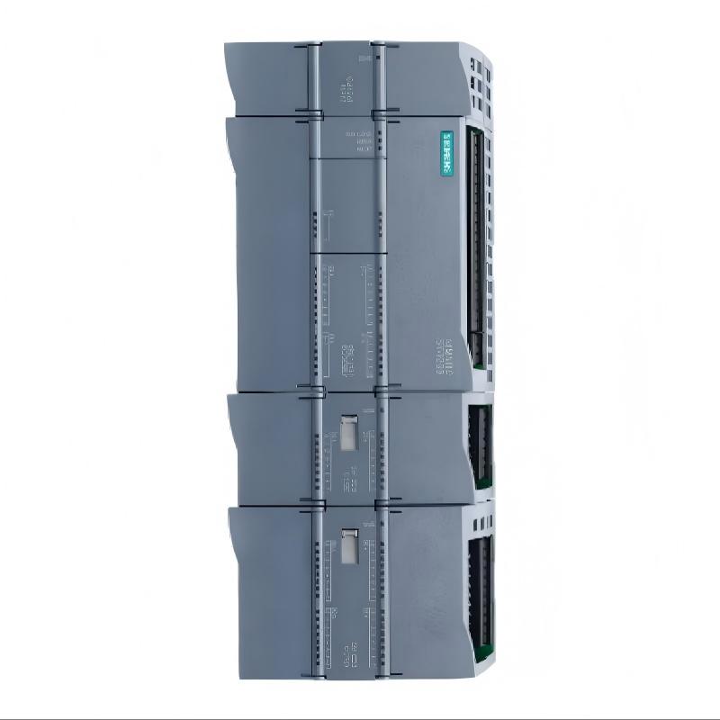
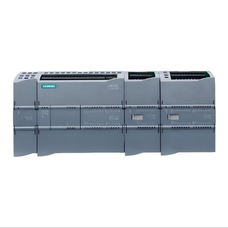
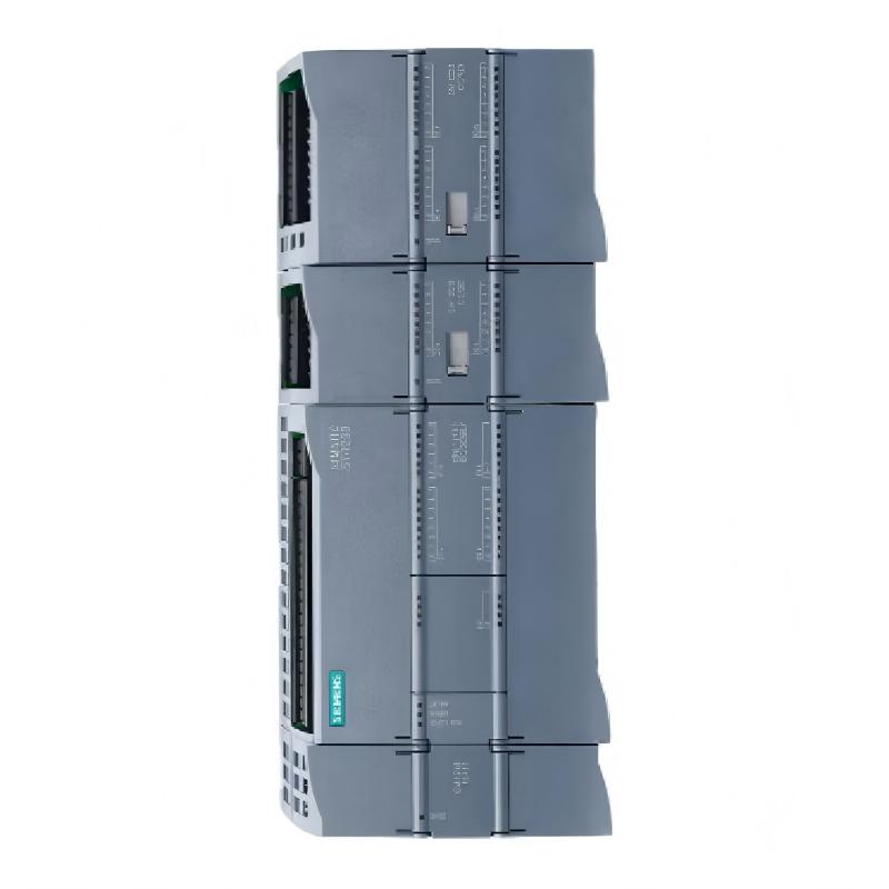
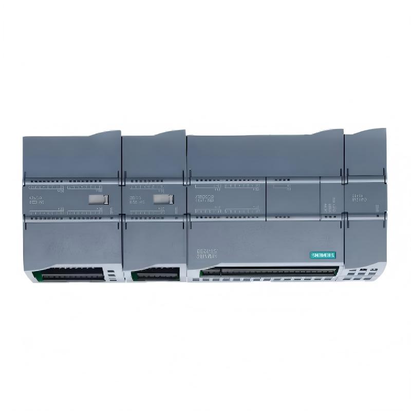
- Siemens
- 6AG1222-1BH32-4XB0
- Digital Output Module
- Germany
- 45 × 100 × 75 mm
- 0.206 kg
- Xiamen, China
- New & In Stock
- T/T, PayPal, Western Union
- 1 Year
- 1-3 Working Days
- DHL, UPS, TNT, FedEx and EMS.
- 24-Hour Service
- COO
- 3
Our advantage

Global Logistics
We have a 10-year logistics and express cooperation agreement, so our products can be shipped to any place in the world.

Brand new and original
Our products are imported in bulk from the place of origin. Because of the cooperative relationship, our products are all original and 100% new.

24-hour service
We provide 7*24 hours service to our customers. We will be there whenever you need us.

Price advantage
All our products are priced very favorably because we have our own warehouse and supply.
| Company Information | |||
| [email protected] | |||
| Mobile | +8615980777398 | ||
| +8615980777398 | |||
| 15980777398 |
1. Product Overview
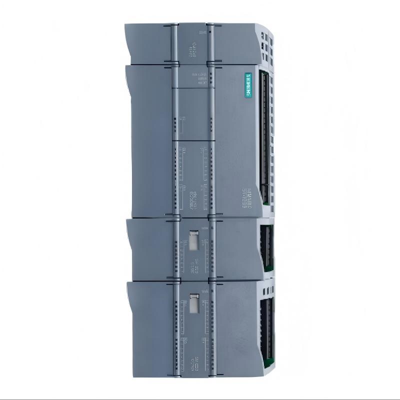
The Siemens 6AG1222-1BH32-4XB0 Digital Output Module is an industrial automation component designed to provide digital output signals within a compatible Siemens control system. Digital output modules connect the PLC control layer with field-level electrical circuits, enabling programmed commands to be transmitted to suitable devices used in machine automation and industrial process control.
In a typical automation system, a programmable logic controller (PLC) processes sensor inputs, evaluates control logic, and determines when specific output signals should be activated or deactivated. The digital output module provides the hardware interface for these commands, supporting discrete operations such as status indication, auxiliary control, and the operation of appropriately rated interface circuits.
The Siemens 6AG1222-1BH32-4XB0 should be identified by its complete ordering number when purchasing, installing, or replacing automation hardware. Modules with similar model numbers may differ in output technology, channel configuration, electrical ratings, and system compatibility. These parameters must be verified against the documentation for the exact product rather than inferred from another model.
With supplied dimensions of 45 × 100 × 75 mm and a weight of 0.206 kg, this module can be evaluated for control cabinet installation, equipment maintenance, and spare-parts planning. Physical dimensions alone, however, do not establish compatibility. Engineers should also confirm mounting requirements, terminal assignments, field power arrangements, and support within the installed controller configuration.
For maintenance engineers, system integrators, and industrial automation spare-parts buyers, accurate identification of the 6AG1222-1BH32-4XB0 helps reduce replacement errors and supports reliable operation throughout the equipment lifecycle.
2. Technical Specifications
| Parameter | Specification |
|---|---|
| Brand | Siemens |
| Model Number | 6AG1222-1BH32-4XB0 |
| Product Type | Digital Output Module |
| Product Family | Siemens industrial automation; confirm exact hardware family |
| Dimensions | 45 × 100 × 75 mm |
| Weight | 0.206 kg |
| Primary Function | Digital signal output |
| Typical Application | PLC-based industrial automation and machine control |
| Output Technology | Verify against the exact model documentation |
| Number of Output Channels | Verify against the exact model documentation |
| Rated Output Voltage | Verify against the exact model documentation |
| Maximum Output Current | Verify against the exact model documentation |
| Output Protection | Verify against the exact model documentation |
| Electrical Connection | Confirm the specified connector and terminal arrangement |
| Mounting Requirements | Confirm against the associated hardware documentation |
| Controller Compatibility | Verify CPU, hardware configuration, and firmware requirements |
The dimensions and weight above are based on the supplied product information. Electrical characteristics should be confirmed before installation or connection to field devices.
The output technology, channel count, voltage rating, and current limits are particularly important when designing an automation system. These specifications determine which loads can be connected, how output circuits should be wired, and whether additional interface components are required.
A digital output module should never be selected solely because its model number resembles that of an existing module. Even closely related products may have different electrical characteristics or configuration requirements.
3. Function and Working Principle
3.1 Digital Output Signal Processing
A digital output module receives commands generated by the PLC program and operates the corresponding output circuits. The PLC determines the required output states by evaluating input signals, internal logic, timers, counters, operating conditions, and programmed interlocks.
For example, when an automated production station reaches a defined operating condition, the PLC may command a signal lamp to illuminate or an interface relay to energize. The output module executes the corresponding electrical switching action when the module, power supply, and connected circuit are operating within their specified limits.
The exact switching behavior depends on the module’s output technology and electrical design. Engineers should verify these details before deciding how the output should be wired or which field devices it can control.
3.2 Discrete Field Device Control
Digital output modules are intended for discrete control tasks in which a device responds to defined signal states. Depending on the verified module specifications, possible applications may include:
- Operating indicator lamps and status signals.
- Sending discrete commands to auxiliary equipment.
- Controlling compatible interface relay circuits.
- Activating suitable solenoid valve circuits.
- Providing control signals to contactors or motor starters.
- Coordinating discrete operating sequences in automated machinery.
The actual number of supported outputs and the permissible electrical load must be checked in the exact product documentation. The presence of a digital output interface does not mean that every type of electrical load can be connected directly.
3.3 Coordination with PLC Logic
The digital output module is one part of a larger control architecture. The PLC executes the application program, while the output module provides the hardware interface between programmed commands and external electrical circuits.
A typical control sequence follows these steps:
- Sensors and input devices provide signals to the PLC.
- The PLC evaluates machine conditions and programmed logic.
- The application determines the required output states.
- The controller updates the output commands.
- The digital output module operates the corresponding output circuits.
- Connected field devices respond to the electrical signals.
- Feedback devices, where installed, report the resulting equipment state.
This arrangement supports repeatable machine sequencing and coordinated operation. Where confirmation of physical operation is required, suitable feedback signals should be incorporated into the control design. A commanded output state does not necessarily confirm that a connected valve, relay, or contactor has operated successfully.
3.4 Electrical Load Compatibility
Electrical compatibility is essential for reliable output operation. An unsuitable load can cause excessive current, unstable switching, overheating, or hardware damage.
Before connecting a field device, engineers should verify:
- Rated output voltage.
- Maximum current permitted per channel.
- Any restrictions on the combined current of output groups.
- Compatibility with the intended load type.
- External fuse and circuit-protection requirements.
- Common-terminal and field-supply arrangements.
- Suppression requirements for inductive loads.
If the load exceeds the output module’s permitted capacity, a suitably rated interface relay or contactor may be required. The interface circuit should be designed around the verified module ratings and the requirements of the connected equipment.
4. Role in Industrial Control Systems
4.1 Machine Automation
In machine automation, digital output modules enable the PLC to issue discrete commands to field-level control circuits. These commands can support operating sequences, status indicators, auxiliary functions, and other programmed machine actions.
Correctly integrated output hardware helps maintain predictable control behavior and simplifies troubleshooting when the wiring, PLC program, and field-device documentation are kept consistent.
4.2 Process Automation
Industrial process systems frequently combine analog measurement with discrete control actions. The PLC may process measurements such as temperature, pressure, flow, or level and then issue a digital command when defined conditions are met.
A digital output module can provide the required interface for suitable discrete control circuits. Its exact application depends on the system architecture, electrical ratings, field-device requirements, and operating procedures.
4.3 Status and Alarm Signaling
Digital outputs may be used to operate indicator lamps, provide discrete status signals, or command external control equipment. These functions help operators monitor operating states and support maintenance procedures.
Critical safety functions require an appropriate safety architecture. A standard digital output should not be treated as a safety-rated output unless the exact hardware and complete system design explicitly support the required safety function.
4.4 Maintenance and Spare-Parts Planning
The complete ordering number is essential when identifying the module for maintenance or replacement. Similar Siemens modules may differ in output technology, channel count, wiring, and controller support.
Maintaining accurate hardware records, including the model number, installation location, I/O assignments, and relevant configuration details, helps reduce troubleshooting time and improves spare-parts management.
5. Industrial Applications
5.1 Manufacturing and Assembly Lines
Manufacturing systems use digital output signals to coordinate machine sequences, activate status indicators, and control compatible auxiliary circuits. The module may be suitable for these tasks when its verified electrical characteristics match the connected equipment.
5.2 Packaging Machinery
Packaging equipment relies on programmed sequences to coordinate product movement, machine states, and auxiliary mechanisms. Digital output modules can provide commands to suitable interface circuits used in these operations.
Where equipment requires high current or separate power switching, an appropriately rated relay, contactor, or motor starter may be necessary. The output module’s specifications should be checked before selecting the control arrangement.
5.3 Material Handling Systems
Conveyors, transfer stations, and automated handling equipment use discrete commands to coordinate operating stages. Digital output modules can participate in these control sequences when integrated with the PLC program, field wiring, feedback devices, and required interlocks.
5.4 Industrial Utility Equipment
Utility systems may use digital outputs to activate auxiliary equipment, indicate operating conditions, or send commands to external devices. Engineers should verify that the module’s electrical characteristics and environmental requirements match the installation.
5.5 OEM Machinery and Retrofit Projects
Original equipment manufacturers and system integrators may evaluate digital output modules for new machine designs, equipment upgrades, and maintenance replacements.
In retrofit projects, it is particularly important to verify controller compatibility, mounting arrangements, terminal assignments, and configuration support. A module that physically fits the existing cabinet is not necessarily a suitable electrical or functional replacement.
6. Installation and System Integration
Installing the Siemens 6AG1222-1BH32-4XB0 Digital Output Module requires attention to product identification, electrical safety, field wiring, hardware configuration, and commissioning. The following procedure is a general engineering checklist; the exact installation steps must follow the documentation for the specific module and associated control system.
6.1 Verify the Product Identification
Before installation, confirm the complete ordering number: 6AG1222-1BH32-4XB0.
Check the product label and verify the module’s electrical characteristics, controller compatibility, mounting method, connector arrangement, and hardware configuration requirements.
Do not assume that specifications from another 6AG1222 model automatically apply to this module. Differences in product variants can affect wiring, addressing, electrical loading, and commissioning.
6.2 Isolate Power Before Installation
Before removing or installing the module, isolate all relevant power sources and follow the site’s lockout/tagout procedures. Verify that the equipment is in a safe state and that externally supplied field circuits cannot energize the wiring unexpectedly.
The PLC supply and field-device supply may be separate. Identify and isolate all relevant circuits before beginning work.
Industrial electrical installation should be performed by qualified personnel. Do not insert, remove, or rewire the module under power unless the exact equipment documentation explicitly permits the procedure and site safety rules authorize it.
6.3 Inspect the Mounting Location
Inspect the installation area for contamination, mechanical damage, loose mounting hardware, and signs of overheating. Confirm that there is adequate clearance for the module, connectors, wire routing, and required service access.
The supplied dimensions are 45 × 100 × 75 mm. Actual cabinet planning should also account for mounting hardware, adjacent devices, cable bends, and any ventilation or clearance requirements specified for the installed system.
6.4 Verify Wiring and Field Loads
Review the approved electrical drawings before connecting field wiring. Confirm terminal assignments, common connections, supply polarity where applicable, wire sizes, and protective devices.
Check the electrical requirements of every connected load. Inductive loads such as relay coils and solenoid valves may require appropriate suppression or interface components depending on the module’s output design.
Never assume that the terminal layout of a similar module is identical. Incorrect wiring can damage the module or the connected equipment.
6.5 Install the Module Correctly
Follow the approved installation procedure for the associated Siemens hardware. Ensure that the module is correctly seated and mechanically secured, and that all required connectors are fully engaged.
Inspect the wiring for loose connections, damaged insulation, pinched conductors, and incorrect routing. Maintain the separation between wiring classes required by the electrical design and applicable standards.
6.6 Configure the PLC Hardware
Where required, configure the module in the appropriate Siemens engineering environment. Select the hardware entry corresponding to the installed product and verify that the controller supports the module.
Review the following items:
- Correct module identification.
- Correct hardware slot or station position.
- Output address assignments.
- Controller and module version compatibility.
- Required configuration parameters.
- Consistency between the project and the physical installation.
If the engineering software does not recognize the module, check the product identification, hardware catalog, firmware requirements, and controller compatibility. Avoid selecting a different module entry simply because its name or appearance is similar.
6.7 Perform Commissioning Tests
Commissioning should begin only after the wiring, hardware configuration, and safety checks are complete.
A general commissioning sequence includes:
- Compare the installation with the approved electrical drawings.
- Verify the supply circuits and protective devices.
- Restore power according to the approved site procedure.
- Check controller and module diagnostic indications.
- Review hardware and configuration messages.
- Test individual outputs under controlled conditions.
- Confirm that each output operates the intended field circuit.
- Verify relevant interlocks and feedback signals.
- Document the commissioning results.
Testing must be coordinated with operations personnel to prevent unexpected machine movement or activation of connected equipment.
6.8 Update Technical Documentation
After commissioning, update the equipment inventory, electrical drawings, I/O address list, and maintenance records as required. Record the full ordering number and any relevant hardware or configuration details.
Accurate documentation supports future troubleshooting, reduces replacement errors, and helps maintenance personnel identify the correct spare part.
7. Compatible System Components
The Siemens 6AG1222-1BH32-4XB0 must be integrated with components that meet its electrical, mechanical, and system requirements. The following table identifies component categories to evaluate; it does not confirm compatibility with any specific part number.
| Component Category | Function | Compatibility Considerations |
|---|---|---|
| Siemens PLC CPU | Executes the automation program and manages output commands | Verify supported hardware family, firmware, and configuration |
| Compatible I/O Hardware | Provides the required mounting and electrical interface | Confirm the module’s installation and connection requirements |
| Industrial Power Supply | Supplies power to the controller or field circuits | Check voltage, current capacity, grounding, and distribution |
| Digital Input Modules | Receive feedback from switches and sensors | Verify controller compatibility and I/O address mapping |
| Interface Relays | Switch or isolate suitable external circuits | Confirm coil voltage, contact ratings, and protection |
| Contactors and Motor Starters | Switch loads requiring separate power handling | Verify control-circuit requirements and protective devices |
| Solenoid Valves | Convert electrical signals into mechanical actions | Check coil specifications and output compatibility |
| Indicator Lamps | Display operating status or alarm states | Confirm voltage, current, and wiring requirements |
| Sensors and Feedback Devices | Provide equipment and process status | Verify input compatibility and PLC logic |
| Engineering Software | Configures hardware and supports diagnostics | Confirm support for the installed controller and module |
Before integrating any component, compare its electrical requirements with the verified module specifications and the overall control-system design.
8. Recommended Alternative Models
When the original module is unavailable, replacement selection should be based on verified electrical and functional equivalence. Similar model numbers and matching external dimensions do not establish interchangeability.
| Alternative Option | Potential Use | Verification Required |
|---|---|---|
| Exact Siemens 6AG1222-1BH32-4XB0 replacement | Preferred for like-for-like maintenance | Confirm the complete ordering number and product condition |
| Verified compatible Siemens digital output module | Potential replacement when the original is unavailable | Compare output technology, channel count, voltage, current, and wiring |
| Module approved for the same controller platform | Potential option for an authorized retrofit | Verify hardware catalog support, firmware, mounting, and address mapping |
| Appropriately rated interface relay arrangement | May adapt a compatible output to a suitable external circuit | Check isolation, coil requirements, contact ratings, and circuit protection |
No specific substitute part number is recommended here because interchangeability cannot be established from the product description and dimensions alone. Confirm the full technical specifications and obtain approval from the responsible controls engineer before substituting a different module.
9. Key Advantages
9.1 Discrete Signal Control
Digital output modules allow PLC programs to issue discrete commands to compatible field circuits. This supports machine sequencing, equipment status indication, and auxiliary control functions.
9.2 Integration with PLC-Based Automation
When supported by the installed controller and correctly configured, the module can operate as part of the wider automation system. Output commands can be managed through the PLC program and documented I/O assignments.
9.3 Compact Physical Dimensions
The specified dimensions of 45 × 100 × 75 mm provide useful information for control cabinet planning and replacement assessment. Actual installation suitability also depends on mounting requirements, connector clearance, and wire routing.
9.4 Reliable Product Identification
Using the complete ordering number helps purchasing and maintenance teams distinguish the required component from similar modules. This is especially important when product variants have different electrical or configuration requirements.
9.5 Support for Maintainable Control Systems
Correct hardware selection, documented wiring, and structured PLC programming make it easier to isolate faults and plan replacements. Long-term reliability still depends on proper electrical loading, installation quality, and maintenance practices.
10. Technical FAQs
Q1: What is the Siemens 6AG1222-1BH32-4XB0 Digital Output Module used for?
It is identified as a digital output module intended for discrete signal output in a compatible industrial automation system. Its exact capabilities depend on the verified specifications of the particular model.
Q2: What are the dimensions and weight?
The supplied dimensions are 45 × 100 × 75 mm, and the supplied weight is 0.206 kg. Verify these details against the product label and applicable documentation when planning a critical replacement.
Q3: How many output channels does the module have?
The channel count should be confirmed using the exact technical documentation for 6AG1222-1BH32-4XB0. Do not assume that a similar model has the same number of channels.
Q4: What output voltage does it support?
The rated output voltage must be verified from the exact product specification. The connected field supply and loads must remain within the module’s permitted electrical limits.
Q5: Can the module directly drive a motor?
Do not assume that a digital output module can directly supply a motor. Motors typically require appropriately rated switching and protection equipment. The module may be able to command a suitable control circuit when its ratings and the system design permit it.
Q6: Can it operate solenoid valves?
It may be suitable for a solenoid-valve circuit if the valve’s voltage, current, and load characteristics match the module’s verified specifications. Check whether an interface relay or suppression device is required.
Q7: What should I check if an output does not activate?
Check the PLC program state, output address, operating mode, interlocks, diagnostic messages, field supply, terminal connections, wiring, and connected load. Follow approved electrical safety procedures when inspecting or measuring the circuit.
Q8: Why might the engineering software not recognize the module?
Possible causes include an incorrect hardware selection, unsupported controller or firmware, an outdated hardware catalog, or a mismatch between the configured and installed products. Verify the full ordering number and system requirements before changing the configuration.
Q9: Can this module replace another Siemens digital output module?
Not automatically. The replacement must satisfy the required electrical, functional, mechanical, and configuration requirements. Compare output technology, channel count, voltage, current, terminal arrangement, mounting, and controller support.
Q10: What should be checked before purchasing a replacement?
Confirm the complete ordering number, product condition, dimensions, weight, output technology, channel configuration, voltage rating, current limits, wiring requirements, and system compatibility. For critical applications, compare the proposed module with the approved spare-parts list and electrical drawings.
11. Conclusion
The Siemens 6AG1222-1BH32-4XB0 Digital Output Module is an industrial automation component intended to provide digital output functions within a compatible PLC-based control system. Digital output modules allow controllers to issue discrete commands to field circuits used for machine sequencing, status indication, and auxiliary process control.
The supplied dimensions of 45 × 100 × 75 mm and weight of 0.206 kg are useful for product identification and installation planning. However, the module’s output technology, channel count, rated voltage, current limits, and controller compatibility must be verified before purchasing or commissioning.
For successful system integration, engineers should confirm the complete ordering number, check field wiring and electrical loads, configure the correct hardware entry, and test output circuits under controlled conditions. Replacement decisions should be based on documented technical equivalence rather than physical appearance or partial model-number similarity.
Careful specification checking and commissioning help reduce installation errors, support efficient maintenance, and improve the reliability of industrial automation systems.