

ProductPRODUCT
Featured products



Contact Us
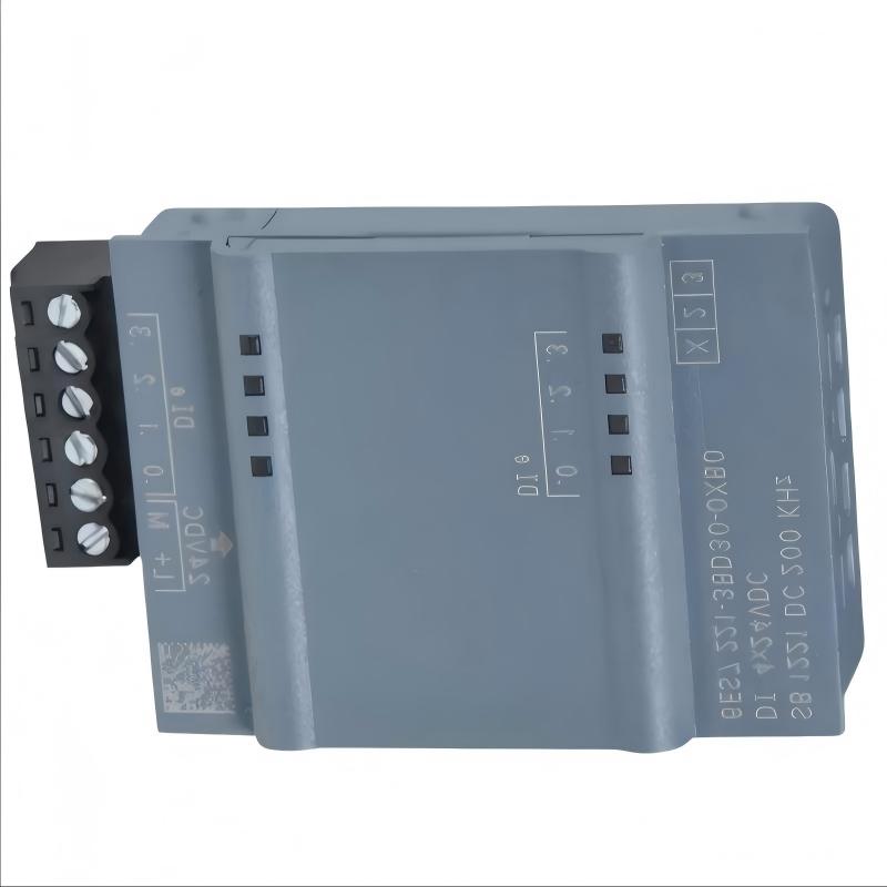
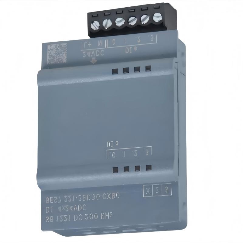
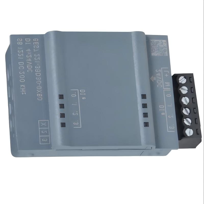
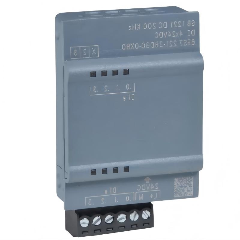
- Siemens
- 6AG1222-1BD30-5XB0
- Digital Output Module
- Germany
- 38 × 62 × 21 mm
- 0.03 kg
- Xiamen, China
- New & In Stock
- T/T, PayPal, Western Union
- 1 Year
- 1-3 Working Days
- DHL, UPS, TNT, FedEx and EMS.
- 24-Hour Service
- COO
- 1
Our advantage

Global Logistics
We have a 10-year logistics and express cooperation agreement, so our products can be shipped to any place in the world.

Brand new and original
Our products are imported in bulk from the place of origin. Because of the cooperative relationship, our products are all original and 100% new.

24-hour service
We provide 7*24 hours service to our customers. We will be there whenever you need us.

Price advantage
All our products are priced very favorably because we have our own warehouse and supply.
| Company Information | |||
| [email protected] | |||
| Mobile | +8615980777398 | ||
| +8615980777398 | |||
| 15980777398 |
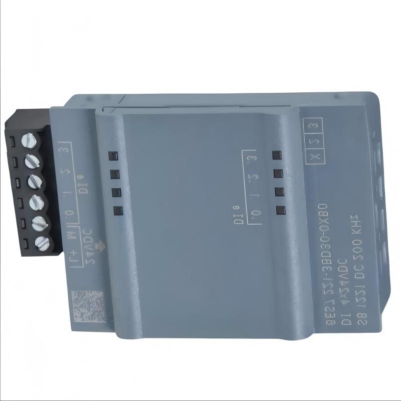
1. Product Overview
The Siemens 6AG1222-1BD30-5XB0 Digital Output Module is an industrial automation component identified by its Siemens SIPLUS catalog number. Digital output modules provide an interface between a programmable logic controller (PLC) and external devices that require discrete control signals.
In industrial automation systems, digital outputs are used to switch control signals between defined states, commonly ON and OFF. Depending on the module’s electrical design and output ratings, these signals may be used to control indicator lamps, relay coils, solenoid valves, or other compatible devices. The module must be selected according to the electrical requirements of the connected loads and the specifications of the complete control system.
A digital output module operates as part of a larger PLC architecture. The CPU executes the user program and determines the required output states, while the output module provides the corresponding electrical interface to the field circuit. Correct configuration and wiring are essential for ensuring that the physical output matches the intended program logic.
The Siemens 6AG1222-1BD30-5XB0 may be considered for applications where its exact specifications and controller compatibility meet the project requirements. Before installation or replacement, engineers should verify the full catalog number, output technology, number of channels, rated voltage, output current, and compatibility with the intended PLC platform.
The supplied dimensions are 38 × 62 × 21 mm, and the specified weight is 0.03 kg. These values are useful for preliminary space planning and spare-parts inventory management.
2. Technical Specifications
| Parameter | Specification |
|---|---|
| Manufacturer | Siemens |
| Model | 6AG1222-1BD30-5XB0 |
| Product Type | Digital Output Module |
| Product Family | SIPLUS product designation; verify the exact supported PLC platform |
| Main Function | Discrete output signal control |
| Dimensions | 38 × 62 × 21 mm |
| Weight | 0.03 kg |
| System Role | PLC output interface |
| Output Technology | Verify the exact electrical design in the product documentation |
| Number of Output Channels | Confirm the exact model specifications |
| Rated Output Voltage | Verify before wiring |
| Rated Output Current | Verify before connecting field loads |
| Output Protection | Confirm the applicable protection features |
| Installation Requirements | Verify the supported controller, mounting, and connection arrangement |
| Typical Applications | Machine control, discrete automation, and equipment signaling |
Technical note: The exact output channel count, output technology, rated voltage, current capacity, and wiring assignments should be confirmed using the documentation for Siemens 6AG1222-1BD30-5XB0. Do not assume that these characteristics are identical to those of a similarly numbered module.
3. Function and Working Principle
The Siemens 6AG1222-1BD30-5XB0 Digital Output Module provides a discrete control interface between a PLC application and external electrical devices. Its precise operation depends on the module’s verified output technology and electrical configuration.
Digital Output Signal Processing
A PLC program evaluates input conditions, internal variables, timers, counters, and control logic to determine whether an output should be activated. The CPU then updates the corresponding output command.
The digital output module converts this command into the electrical state supported by its output circuit. A connected device responds according to its own electrical characteristics and the design of the field circuit.
Control of External Devices
Digital outputs are commonly used for discrete switching applications. Depending on the module’s ratings and output design, possible applications include:
- Operating suitable indicator lamps.
- Activating compatible relay or contactor control circuits.
- Switching appropriate solenoid-valve control circuits.
- Providing discrete status or enable signals to other equipment.
- Coordinating machine operating sequences through external interfaces.
The module should not be assumed to support every type of load. Voltage, current, inrush characteristics, switching frequency, and load protection must be checked before connection.
Coordination with PLC Logic
The output module works together with the CPU and the configured application program. For example, a machine-control program may activate an output after a sensor detects a workpiece and all required interlocks are satisfied.
The module then provides the corresponding output state to the connected circuit. If the device does not respond, the cause may be related to the program, module configuration, electrical supply, wiring, protection devices, or the field device itself.
Output Monitoring and Diagnostics
Depending on the exact module and controller configuration, system diagnostics may help identify configuration errors or output-related faults. Available diagnostic functions should be verified for the specific hardware revision and supported engineering software.
4. Role in Industrial Control Systems
The 6AG1222-1BD30-5XB0 serves as a discrete output interface within a compatible Siemens automation architecture. Its role is to translate PLC output commands into the electrical switching actions required by the application.
Discrete machine control: The module can support ON/OFF control of suitable devices according to the PLC program and its electrical ratings.
Sequence coordination: Output commands can be used to coordinate individual stages of machine operation, such as enabling an actuator or signaling a process transition.
Field-device interface: The module connects the controller’s logic with external control circuits, helping organize the relationship between program execution and physical equipment.
System integration: It operates as part of a complete automation system that may include a PLC CPU, power supply, input modules, communication interfaces, field wiring, and connected devices.
Maintenance and replacement: Accurate identification of the catalog number helps maintenance teams assess spare-part requirements, diagnose output faults, and avoid selecting an incompatible replacement.
Reliable operation depends on the entire control path. A correct output command does not guarantee that the connected device will operate if the external supply, wiring, protective components, or load is faulty.
5. Industrial Applications
Manufacturing and Assembly Equipment
Manufacturing machines use digital output signals to coordinate discrete operating steps. A compatible output module may control indicators, auxiliary relays, and other suitable devices used in assembly and production processes.
Packaging Machinery
Packaging equipment often relies on discrete commands for sequence control, machine status signaling, and actuator interfaces. The module’s suitability depends on the required electrical characteristics and switching demands.
Conveyor and Material Handling Systems
Conveyor systems use PLC outputs to coordinate equipment states and command suitable control interfaces. Motor power should normally be switched through appropriately rated motor-control equipment rather than directly through an output module unless the module specifications explicitly permit the load.
Industrial Equipment Control Panels
Digital output modules are used in control cabinets to connect PLC logic with external electrical circuits. Proper terminal identification, wiring organization, circuit protection, and documentation are essential for safe and maintainable installations.
Process Equipment
Process machinery may use digital outputs for discrete actions such as enabling auxiliary devices, operating compatible valves, or signaling equipment states. The application must account for the characteristics of each connected load.
Automation System Maintenance
For existing Siemens PLC installations, the 6AG1222-1BD30-5XB0 may be relevant when reviewing output hardware, identifying replacement parts, or troubleshooting discrete-control faults. Compatibility should be verified before the module is installed in an existing system.
6. Installation and System Integration
Correct installation of the Siemens 6AG1222-1BD30-5XB0 requires verification of the supported PLC platform, output electrical characteristics, wiring arrangement, and application configuration.
Step 1: Verify the Complete Catalog Number
Check the module label and confirm the full number, including the “6AG” prefix and the “5XB0” suffix. Record any available hardware revision or identification information.
Do not select a replacement solely because its model number appears similar.
Step 2: Confirm Controller Compatibility
Verify that the module is supported by the intended PLC family, CPU, mounting arrangement, and engineering software. Check the hardware configuration requirements and any restrictions associated with the exact product version.
The product designation alone should not be used to infer the complete controller compatibility list.
Step 3: Verify the Electrical Characteristics
Before connecting any field device, confirm the output technology, rated voltage, maximum current, channel arrangement, and permitted load characteristics.
Determine whether the connected device requires a separate power supply, an interposing relay, or another interface. Select protective components according to the actual circuit requirements.
Step 4: Isolate Power Before Installation
Follow the facility’s lockout/tagout procedure and the manufacturer’s safety instructions. Isolate relevant power sources before installing the module or modifying field wiring.
Use appropriate electrostatic-discharge precautions when handling electronic components. Inspect the module and connection points for visible damage before installation.
Step 5: Install and Connect the Module
Mount and connect the module according to the documented installation procedure for the exact model and controller platform. Follow the correct terminal assignments and wiring diagrams.
Observe the specified conductor sizes, grounding requirements, and protective-device recommendations. Keep signal and power wiring organized to reduce wiring errors and simplify future troubleshooting.
Step 6: Configure Output Addresses
Verify the module’s position and output addresses in the PLC hardware configuration. Ensure that the application program references the intended channels and that the physical wiring corresponds to the programmed output assignments.
Incorrect addressing can activate an unintended circuit even when the module itself is operating correctly.
Step 7: Perform Commissioning Tests
After the installation and wiring checks are complete, restore power according to the approved procedure. Review the controller’s diagnostic information and module status where available.
Test each required output under controlled conditions. Confirm that the output command, electrical state, and connected device response agree with the intended control sequence.
Check interlocks and safety-related functions before returning equipment to normal operation.
Step 8: Document the Installation
Record the module model, hardware revision, output assignments, field wiring, connected loads, and commissioning results. Update the electrical drawings and PLC configuration records when changes are made.
Important: Output modules are not substitutes for properly designed machine-safety systems. Do not bypass safety interlocks or force outputs on operating equipment without an approved test procedure and appropriate safeguards.
7. Compatible System Components
The 6AG1222-1BD30-5XB0 should be used only with system components and field devices confirmed to be suitable for the exact module configuration.
| Component Type | Function | Integration Considerations |
|---|---|---|
| Compatible Siemens PLC CPU | Executes application logic and commands outputs | Verify support for the exact module and hardware configuration |
| Compatible Mounting or Connection Hardware | Provides module installation and electrical connection | Confirm the required base, carrier, or mounting arrangement |
| PLC Power Supply | Provides power to the control system | Verify voltage, capacity, and system requirements |
| Digital Input Modules | Receive discrete signals from sensors and switches | Confirm signal voltage, wiring, and address configuration |
| Digital Output Field Wiring | Connects module outputs to external circuits | Follow the exact terminal assignments and output ratings |
| Interposing Relays | Provide a switching interface for suitable external loads | Select appropriate coil voltage, contact ratings, and protection |
| Contactors and Motor Starters | Switch power to motors and other equipment | Use suitable control interfaces and protective devices |
| Solenoid Valves | Perform discrete pneumatic or hydraulic actions | Confirm electrical ratings and required suppression |
| Sensors and Limit Switches | Provide feedback to the PLC | Connect through appropriate input modules |
| Engineering Software | Configures hardware and application logic | Verify support for the exact controller and module revision |
This table describes general component categories rather than a guaranteed compatibility list. Confirm the module’s supported PLC platform, connection hardware, and electrical characteristics before purchasing or commissioning related components.
8. Recommended Alternative Models
If the Siemens 6AG1222-1BD30-5XB0 is unavailable, the replacement should be selected by comparing the exact electrical and system requirements.
| Model or Option | Product Category | Selection Considerations |
|---|---|---|
| Siemens 6AG1222-1BD30-5XB0 | Digital Output Module | Reference model for identification and replacement evaluation |
| Corresponding Siemens Standard-Series Module | Digital Output Module | Verify the exact underlying product designation and specification differences |
| Other Compatible Siemens Digital Output Modules | PLC Output Modules | Compare output technology, voltage, current, channel count, and connection requirements |
| Compatible Digital Output Interface | External Switching Interface | Consider only when the system design and electrical requirements permit it |
| Compatible Modern PLC I/O Platform | Digital Output Hardware | Assess controller compatibility, wiring changes, program migration, and commissioning needs |
Replacement recommendation: Do not assume that a standard Siemens module and a SIPLUS-designated module are interchangeable without checking the exact documentation. Compare the catalog number, environmental specifications, output technology, channel arrangement, electrical ratings, mounting requirements, and controller support.
A replacement with a different output technology or channel configuration may require wiring changes, hardware reconfiguration, or application-program modifications.
9. Key Advantages
Discrete Output Control
Digital output technology enables the PLC to command discrete electrical states for suitable external control circuits.
Integration with Automated Equipment
Within a compatible system, the module can connect PLC logic with indicators, relay interfaces, actuators, and other devices that require discrete control signals.
Support for Sequence-Based Applications
Output commands can be used to coordinate programmed machine sequences and process steps when the control program and connected equipment are configured correctly.
Compact Physical Dimensions
The supplied dimensions of 38 × 62 × 21 mm and weight of 0.03 kg provide useful reference information for preliminary space planning and spare-parts management.
Structured System Maintenance
The full catalog number supports accurate product identification and helps reduce errors when reviewing inventories or sourcing replacement components.
Modular Control Architecture
When supported by the intended PLC platform, the output module can form part of a larger system combining CPU processing, input acquisition, discrete outputs, communications, and field-device interfaces.
10. Technical FAQs
Q1: What is the Siemens 6AG1222-1BD30-5XB0?
It is identified as a Siemens digital output module. Its exact electrical characteristics and supported PLC platform should be confirmed using the product documentation for the complete catalog number.
Q2: What are the dimensions and weight of this module?
The supplied specifications list dimensions of 38 × 62 × 21 mm and a weight of 0.03 kg. Confirm the physical dimensions and mounting requirements against the actual unit before installation.
Q3: What type of output does the module provide?
The precise output technology should be verified for the exact model. Do not assume that it uses relay, transistor, or another output technology without confirming the applicable specification.
Q4: Can the module directly control a motor?
Do not assume that a digital output module can directly switch motor power. Motors generally require suitable motor starters, contactors, overload protection, and other protective equipment. The PLC output may control an appropriate interface if the electrical ratings permit it.
Q5: What should be checked if an output does not activate?
Check the PLC program, output address, controller and module diagnostics, module seating, wiring, external supply, protective devices, and connected load. Follow approved isolation procedures before inspecting electrical connections.
Q6: Can the module replace another Siemens digital output module?
Not automatically. Confirm the complete catalog number, output technology, rated voltage, current capacity, channel count, connection arrangement, environmental requirements, and controller compatibility.
Q7: Does the module require separate field power?
That depends on the module’s electrical design and the connected circuit. Consult the wiring diagram and technical specifications to determine the required power arrangement.
Q8: What is the importance of the “6AG” prefix?
The prefix is part of the product’s full identification and may indicate a specific Siemens product designation or variant. Replacement decisions should be based on the complete catalog number and documented specifications rather than the base number alone.
Q9: Can the module be used in a new automation project?
Its suitability depends on the required PLC platform, engineering tools, system lifecycle, and technical specifications. Verify support and compare the available alternatives before designing a new installation around this module.
Q10: What information should be provided when ordering a replacement?
Provide the full catalog number, suffix, available hardware revision, installed PLC family, required output characteristics, connection hardware, and application requirements. A clear photograph of the module label can help reduce selection errors.
11. Conclusion
The Siemens 6AG1222-1BD30-5XB0 Digital Output Module is intended to provide discrete output control within a compatible industrial automation system. It serves as the interface between PLC output commands and external circuits used in machine automation, equipment signaling, and process control.
The supplied dimensions of 38 × 62 × 21 mm and weight of 0.03 kg are useful for product identification and preliminary installation planning. However, reliable integration requires confirmation of the module’s exact output technology, channel configuration, electrical ratings, connection requirements, and PLC compatibility.
For industrial automation engineers, maintenance teams, and spare-parts purchasers, verifying the complete 6AG1222-1BD30-5XB0 catalog number before ordering or installation is essential for minimizing compatibility risks and maintaining reliable system operation.