

ProductPRODUCT
Featured products
Contact Us
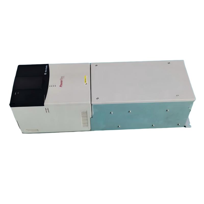
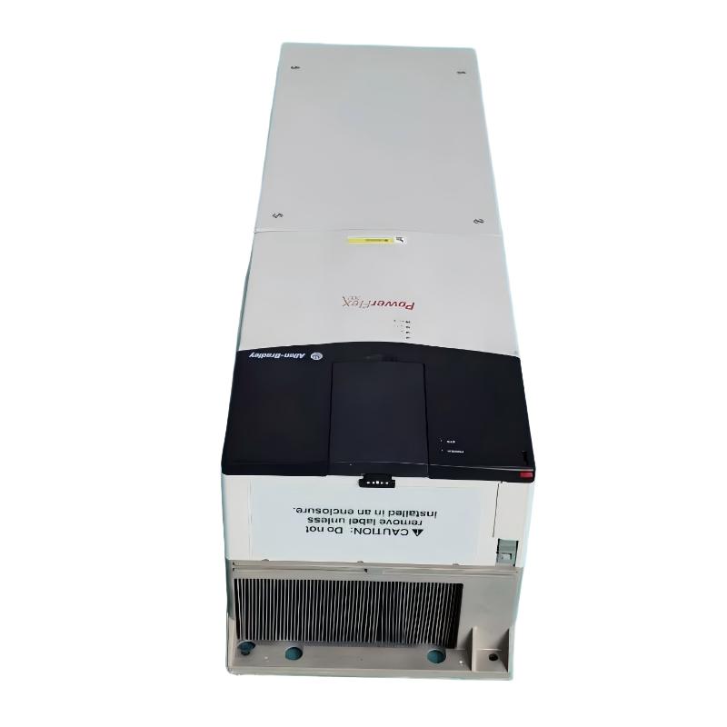
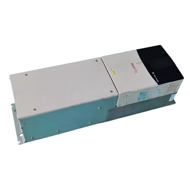
- Allen Bradley
- 20BC170A3ANNACC0
- PowerFlex AC Drive
- USA
- 689.6 × 308.9 × 275.4 mm
- 37.19kg
- Xiamen, China
- New & In Stock
- T/T, PayPal, Western Union
- 1 Year
- 1-3 Working Days
- DHL, UPS, TNT, FedEx and EMS.
- 24-Hour Service
- COO
- 2
Our advantage

Global Logistics
We have a 10-year logistics and express cooperation agreement, so our products can be shipped to any place in the world.

Brand new and original
Our products are imported in bulk from the place of origin. Because of the cooperative relationship, our products are all original and 100% new.

24-hour service
We provide 7*24 hours service to our customers. We will be there whenever you need us.

Price advantage
All our products are priced very favorably because we have our own warehouse and supply.
| Company Information | |||
| [email protected] | |||
| Mobile | +8615980777398 | ||
| +8615980777398 | |||
| 15980777398 |
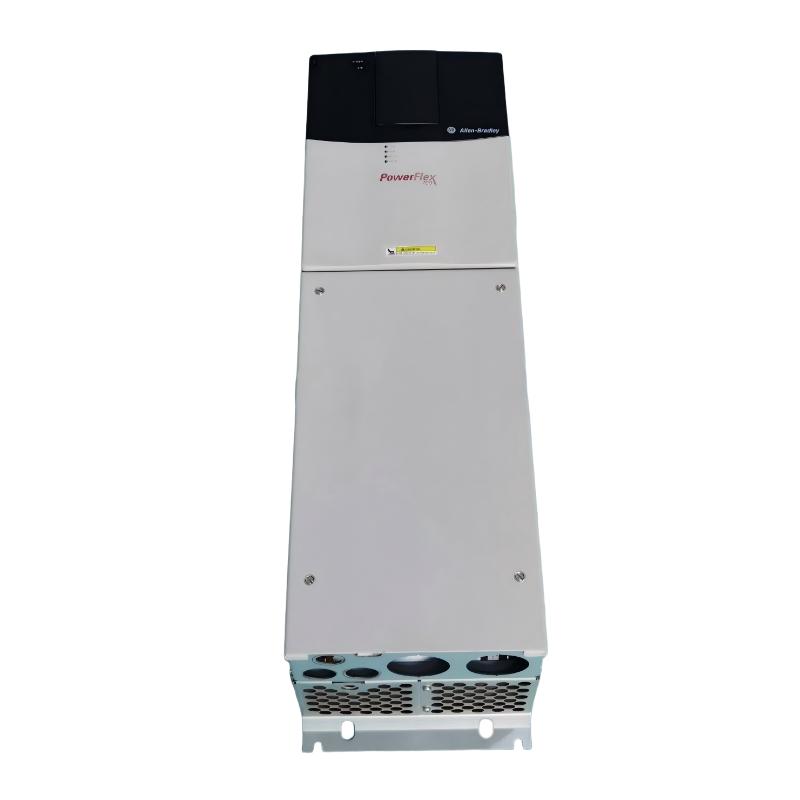
Allen-Bradley 20BC170A3ANNACC0 Industrial AC Drive: Product Specifications, Features, Applications, and Model Recommendations
1. Product Overview
The Allen-Bradley 20BC170A3ANNACC0 is an industrial variable-frequency AC drive associated with the PowerFlex 700 series. This type of equipment is designed to control the speed, torque, acceleration, and deceleration of AC motors in industrial automation systems.
Variable-frequency drives are widely used in manufacturing plants, material-handling systems, pumps, fans, conveyors, and other applications where motor speed needs to be adjusted to match operating requirements. By regulating the electrical frequency and voltage supplied to a motor, a drive can provide more flexible process control than a motor operating directly from a fixed-frequency power supply.
The PowerFlex 700 family is designed for industrial applications requiring adjustable motor speed, configurable control functions, and integration with automation equipment. Depending on the specific drive configuration, available functions may include sensorless vector control, closed-loop vector control, programmable acceleration and deceleration, motor protection, and communication with industrial control systems.
The exact catalog number is important because the drive’s power rating, input voltage, enclosure, feedback options, communications, and other configuration details can differ substantially between closely related models.
The following description distinguishes established product-family characteristics from specifications that require confirmation against the exact catalog configuration. No external lookup is used, and unverified numerical specifications are not presented as confirmed factory data.
2. Product Identification and Basic Information
|
Item |
Product Information |
|---|---|
|
Model |
|
|
Brand |
Allen-Bradley |
|
Product family |
PowerFlex 700 |
|
Product category |
Industrial variable-frequency AC drive |
|
Equipment type |
Adjustable-frequency motor controller |
|
Primary function |
Control of AC motor speed and torque |
|
Typical application |
Industrial machinery and automated production equipment |
|
Motor control |
Variable-frequency motor control; exact control options depend on configuration |
|
Installation environment |
Industrial electrical control panels or suitable equipment enclosures |
|
Control architecture |
Local drive control and integration with external automation systems, depending on installed options |
|
Motor compatibility |
Must be matched to motor voltage, current, power, and control requirements |
|
Dimensions |
Exact dimensions require confirmation for this catalog configuration |
|
Weight (kg) |
Exact net weight requires confirmation for this catalog configuration |
|
Product status |
Confirm availability, revision, and service support before procurement |
The catalog number should be retained exactly as written when requesting a quotation, checking a replacement, or comparing an existing installation. Similar-looking PowerFlex 700 catalog numbers do not necessarily represent electrically interchangeable products.
3. Detailed Technical Specifications
The following table summarizes the principal electrical, control, and mechanical characteristics associated with the 20BC170A3ANNACC0 configuration. Dimensions and weight should be treated separately from electrical ratings because they can depend on the drive enclosure and packaging arrangement.
|
Parameter |
Specification |
|---|---|
|
Model |
20BC170A3ANNACC0 |
|
Brand |
Allen-Bradley |
|
Series |
PowerFlex 700 |
|
Product type |
Variable-frequency AC drive |
|
Rated input voltage |
400 V AC nominal |
|
Supported voltage class |
380–480 V AC |
|
Input phase |
Three-phase |
|
Supply frequency |
50 Hz nominal for the specified configuration |
|
Continuous output current |
170 A at the applicable normal-duty rating |
|
Heavy-duty output current |
170 A-class drive; exact duty-specific continuous rating must be checked against the rating plate |
|
Input current |
Approximately 164 A at 400 V AC, subject to the specified duty and configuration |
|
Nominal power classification |
Approximately 90 hp in the applicable published normal-duty configuration; verify the exact motor power rating before selection |
|
Output voltage |
Variable, up to the applicable rated motor voltage |
|
Maximum output frequency |
Up to 420 Hz, subject to programming and operating limits |
|
Motor control methods |
Sensorless vector control and configurable V/Hz control |
|
Speed regulation |
Vector-control performance depends on motor tuning and feedback configuration |
|
Acceleration and deceleration |
Programmable ramp functions |
|
Overload protection |
Drive and motor protection functions, subject to the applicable configuration |
|
Dynamic braking |
No assumption should be made that an internal braking resistor is fitted; confirm the installed braking hardware |
|
Feedback |
Confirm the installed feedback option before using closed-loop control |
|
Communication |
ControlNet coaxial is indicated for this catalog configuration; verify the actual installed communication option |
|
Analog inputs |
2 |
|
Analog outputs |
2 |
|
Digital inputs |
6 |
|
Digital outputs |
3 |
|
Operator interface |
LCD display and programming keypad |
|
Enclosure classification |
IP20 / NEMA Type 1 for the relevant open-panel configuration |
|
Internal EMC filtering |
EMC filter with common-mode choke indicated for the configuration |
|
Operating temperature |
Up to approximately 50°C for applicable ratings, subject to derating |
|
Relative humidity |
5–95%, non-condensing |
|
Maximum altitude without derating |
Approximately 1,000 m |
|
Dimensions (H × W × D) |
Approximately 850 × 403.9 × 275.5 mm; verify the applicable enclosure drawing |
|
Weight (kg) |
Approximately 71.44 kg for the listed drive configuration; packaging and enclosure options may change the total |
|
Installation |
Industrial control cabinet or approved installation arrangement |
|
Maintenance |
Periodic inspection, cooling-system cleaning, terminal checks, and fault-history review |
Important power-rating distinction: A drive’s current rating is often more useful than its horsepower or kilowatt label when matching it to a motor. Different overload categories can result in different allowable motor ratings for the same drive. The motor’s rated current, operating duty, supply voltage, ambient temperature, and load profile should all be checked before the drive is commissioned.
3.1 Electrical Performance
The 20BC170A3ANNACC0 belongs to a high-current industrial drive class intended for substantial three-phase AC motor loads. Its principal role is to convert fixed-frequency AC input power into a controlled output suitable for variable-speed motor operation.
The drive’s output frequency can be adjusted to change motor speed, while its control algorithms manage the relationship between voltage, frequency, and motor current. When correctly sized and tuned, this makes it suitable for machinery that must start gradually, maintain a selected speed, or change operating speed in response to process requirements.
The available overload capability is particularly important for machines that experience short periods of elevated torque demand. Conveyor starts, loaded mechanical systems, and certain process machines can require more torque during acceleration than during steady-state operation. The allowable overload current and duration must be selected from the applicable drive ratings rather than assumed from the model number alone.
3.2 Control and Communication
The PowerFlex 700 family supports industrial motor control and integration with automation equipment. Depending on the configuration, the drive can receive speed references and operating commands through local controls, digital inputs, analog signals, or a supported communication interface.
The exact communication module is a critical purchasing detail. A drive fitted with a ControlNet interface is not automatically equivalent to one configured for EtherNet/IP or another industrial network. The replacement must match the control system’s communication requirements, addressing arrangements, network architecture, and available software support.
3.3 Mechanical and Environmental Specifications
The enclosure and installation arrangement determine how well the drive is protected against dust, moisture, and accidental contact. An IP20 or NEMA Type 1 arrangement is generally intended for a suitably protected indoor electrical installation rather than direct exposure to water, weather, or conductive contamination.
Adequate ventilation is essential because power conversion produces heat. The panel should provide sufficient clearance around air inlets and outlets, and the installation should account for the drive’s heat dissipation, ambient temperature, and nearby heat-generating equipment.
The listed dimensions and weight are useful for preliminary planning, but the final cabinet layout should be based on the exact mechanical drawing. This is especially important when replacing an older drive in an existing cabinet, where cable routing, mounting holes, door clearance, and ventilation openings may already be fixed.
4. Product Introduction
The 20BC170A3ANNACC0 is an industrial AC drive designed to provide controlled motor operation in demanding automation environments. Rather than allowing a motor to run continuously at a speed determined only by the electrical supply frequency, it allows the machine’s operating speed to be adjusted to suit production requirements.
In a typical installation, incoming three-phase power is processed by the drive’s power-conversion circuitry. The resulting controlled electrical output allows the motor to accelerate, operate, and decelerate according to programmed commands. This is particularly useful in systems where sudden starts or stops can cause mechanical shock, product movement, excessive current demand, or process instability.
The drive also provides a control interface between the motor and the wider automation system. Depending on the installed options, operators and control equipment can issue run commands, change speed references, monitor operating conditions, and respond to detected faults.
For an industrial facility, the value of a variable-frequency drive extends beyond speed adjustment. Properly engineered motor control can improve process consistency, reduce unnecessary mechanical stress, and support more efficient operation when the process does not require the motor to run continuously at full speed.
The 20BC170A3ANNACC0 is therefore best considered as one component of a complete motor-control system. Its suitability depends on the motor, driven machine, electrical supply, protection equipment, control architecture, and operating environment as a whole.
5. Main Product Applications
5.1 Conveyor Systems and Material Handling

Conveyor systems often need adjustable speed to coordinate the movement of raw materials, packaged goods, or finished products. A variable-frequency drive allows operators to match conveyor speed to upstream and downstream equipment.
Gradual acceleration can reduce mechanical shock to belts, couplings, gearboxes, and loaded conveyor structures. Controlled deceleration can also help reduce product displacement and improve coordination between successive production stages.
For heavier conveyors, the drive must be selected according to the starting torque, conveyor loading, acceleration time, and expected frequency of starts and stops. Applications with frequent high-torque starts may require a more conservative rating or a different drive configuration.
5.2 Industrial Pumps

Pump applications frequently require flow or pressure to change in response to process demand. A drive can adjust motor speed instead of relying exclusively on throttling valves or other mechanical flow-control methods.
In suitable centrifugal pumping systems, reducing speed can reduce energy consumption when the process permits a lower flow rate. The actual savings depend on the pump curve, system resistance, static head, and required operating point.
The drive should be matched to the pump motor’s current and torque requirements, with suitable protection for dry-running, low-flow, pressure, and other process conditions where required by the application.
5.3 Fans and Industrial Blowers
Fans and blowers are used in ventilation, dust extraction, process cooling, combustion-air systems, and industrial air handling. Variable-speed operation allows airflow to be adjusted as operating conditions change.
When a fan system can operate at reduced speed, a drive may help lower energy consumption and reduce the noise associated with unnecessary high-speed operation. Gradual starting can also reduce the mechanical stress associated with accelerating large rotating assemblies.
The engineering assessment should include fan inertia, minimum operating speed, airflow requirements, motor cooling, and any resonance frequencies that must be avoided.
5.4 Mixers and Process Machinery
Mixers, agitators, and similar process machines may require different operating speeds during filling, mixing, and discharge. A drive allows speed settings to be adjusted to suit the material and process stage.
For these applications, the main considerations are torque demand, material viscosity, startup loading, and the length of time the motor must operate at low speed. High-inertia or high-torque machines may require careful ramp programming and verification of the drive’s overload capability.
5.5 Manufacturing and Automated Production Lines
Production machinery often operates as part of a coordinated system involving sensors, programmable logic controllers, operator interfaces, and other drives.
A properly integrated drive can help maintain consistent machine speed and provide status information to the control system. This is useful for production lines that need repeatable operating sequences, coordinated conveyor movement, or adjustable machine throughput.
When selecting a replacement, compatibility with the existing control network and the installed drive configuration can be just as important as the electrical rating.
5.6 General Industrial Motor Control
The drive can also be considered for suitable industrial machinery using three-phase AC motors, provided that the load requirements fall within its rated operating limits.
Examples include selected material-processing machines, industrial handling equipment, mechanical auxiliary systems, and production equipment requiring adjustable speed. It should not be assumed to suit every motor or load merely because the nominal voltage matches.
6. Main Advantages of the 20BC170A3ANNACC0
6.1 Adjustable Motor Speed
One of the main advantages of a variable-frequency drive is the ability to adjust motor speed to match the actual requirements of a machine.
In applications where production speed changes throughout the day, adjustable operation can help avoid running equipment faster than necessary. It also allows operators to establish different operating speeds for different products, production stages, or process conditions.
This flexibility is especially useful in conveyor systems, pumps, fans, and machinery that does not require constant full-speed operation.
6.2 Smooth Acceleration and Deceleration
The drive provides programmable acceleration and deceleration functions. Instead of applying full operating speed immediately, the motor can increase or decrease speed over a selected period.
This can reduce mechanical shock to couplings, belts, gearboxes, shafts, and connected machinery. It may also reduce the likelihood of product movement caused by abrupt changes in conveyor speed.
The appropriate ramp time depends on the motor, load inertia, required production cycle, and stopping conditions.
6.3 Industrial Motor Control Capability
The PowerFlex 700 family supports industrial motor-control functions, including vector-control options and configurable V/Hz operation.
Vector control can provide improved speed and torque regulation compared with basic scalar control when the application is properly configured. Motor data entry and tuning are important to achieving the expected performance.
The exact control functions available should be confirmed for the specific catalog number and installed options.
6.4 Integration with Existing Automation Equipment
A correctly configured drive can work as part of an industrial automation system, accepting commands and providing operating information through supported control interfaces.
This can help integrate motor operation into production sequences, equipment interlocks, and supervisory monitoring. However, communication compatibility depends on the installed module, firmware, network type, and control-system configuration.
6.5 Protection and Fault Monitoring
Industrial drives typically incorporate protective functions for abnormal operating conditions. Depending on the configuration, these may include overcurrent, overvoltage, undervoltage, overheating, and ground-fault detection.
These functions can help protect equipment from certain electrical or operating faults and make troubleshooting more systematic.
A drive’s protective functions do not replace correctly selected branch-circuit protection, grounding, motor thermal protection, or machine safety systems.
6.6 Potential Energy Savings
In suitable variable-torque applications, especially centrifugal pumps and fans, reducing motor speed can significantly reduce the power required by the driven machine.
Energy savings are not guaranteed simply by installing a drive. They depend on the operating profile, system characteristics, control strategy, and the proportion of time spent at reduced speed.
For constant-torque machinery, the potential savings must be evaluated against the actual mechanical load and process requirements.
6.7 Suitability for Demanding Industrial Loads
The 170 A current class makes this model relevant to substantial industrial motor-control applications. Correctly selected and installed, a drive in this class can support equipment that requires controlled operation at significant motor currents.
The final selection must nevertheless account for overload duty, ambient temperature, altitude, switching frequency, motor cable length, and the application’s starting and braking requirements.
6.8 Support for Equipment Replacement Projects
When an existing machine already uses a compatible PowerFlex 700 drive, retaining the same product family may simplify certain aspects of maintenance and replacement planning.
Existing documentation, wiring drawings, parameter records, and operator procedures may provide a useful starting point. Nevertheless, the replacement’s complete catalog number, communication options, I/O voltage, enclosure, and firmware compatibility must be checked before installation.
7. Recommended Models from the Same Series or Related Product Family
The following five models are candidates for comparison when maintaining a PowerFlex 700 installation. The first three share the same main catalog-number prefix and current class as the target model, while the remaining two are related catalog-number candidates for further verification.
The exact suffix matters: different suffixes can indicate differences in communications, feedback, I/O, filtering, or other options. These models should therefore be regarded as candidates for evaluation, not as automatically interchangeable replacements.
Mechanical data note: dimensions and weight are included for every model. Where an exact model-specific mechanical value cannot be established confidently, it is marked as requiring verification rather than assigned an invented figure.
|
Model |
Series / relationship |
Electrical and control parameters |
Dimensions (H × W × D) |
Weight (kg) |
|---|---|---|---|---|
|
20BC170A3ANNACC0 |
PowerFlex 700; reference model |
400 V AC nominal; three-phase; 170 A class; ControlNet configuration indicated; vector control |
Approx. 850 × 403.9 × 275.5 mm; verify enclosure |
Approx. 71.44 |
|
20BC170A3ANNADB0 |
PowerFlex 700; same main rating class |
380–480 V AC class; three-phase; 170 A class; option configuration differs from reference |
Exact drawing required |
Not verified |
|
20BC170A3ANNAND0 |
PowerFlex 700; related configuration |
380–480 V AC class; three-phase; 170 A class; no internal communication module indicated for this variant |
Exact drawing required |
Not verified |
|
20BC170A3AYNADD0 |
PowerFlex 700; related configuration |
380–480 V AC class; three-phase; 170 A class; verify control, filtering, and feedback options |
Exact drawing required |
Not verified |
|
20BC140A0AYNANC0 |
PowerFlex 700; candidate lower-current class |
Voltage class, current rating, motor power, and options must be confirmed against the complete catalog number |
Exact drawing required |
Not verified |
7.1 Model Comparison and Selection Advice
20BC170A3ANNACC0 is the natural reference point if the objective is to understand or replace the existing unit. Its nominal voltage class and current rating should be used as the initial comparison criteria.
20BC170A3ANNADB0 is worth evaluating when looking for a closely related drive. Even though the main model prefix is similar, the option suffix should be checked against the original installation’s communication and control requirements.
20BC170A3ANNAND0 is a candidate where a drive without an internal communication module may be appropriate. It should not be selected if the machine depends on an integrated communication interface that the proposed replacement does not provide.
20BC170A3AYNADD0 is another related catalog-number candidate. The exact differences must be identified from the full catalog definition and rating information before it is considered for procurement.
20BC140A0AYNANC0 is included as a possible lower-current comparison, not as a drop-in replacement. A lower-current model may be suitable for a different motor or a lighter-duty application, but it must not be substituted for a 170 A-class drive without checking motor current and load requirements.
For any replacement, compare the following items before making a decision:
-
Rated input voltage and supply phase.
-
Continuous output current under the actual operating duty.
-
Motor horsepower or kilowatt rating at the intended voltage.
-
Communication interface and installed control options.
-
Digital and analog I/O requirements.
-
Enclosure rating and mounting dimensions.
-
Drive weight and cabinet support requirements.
-
Braking, feedback, and overload requirements.
-
Firmware, parameter compatibility, and commissioning requirements.
8. Five Popular or Widely Used Allen-Bradley Models for Comparison
The following models cover different drive classes within the Allen-Bradley product range. They are intended to help compare compact machinery drives, general-purpose drives, and higher-performance industrial drives.
They are not all direct alternatives to a 170 A PowerFlex 700. In particular, compact PowerFlex 525 models generally serve much smaller motor applications. The appropriate choice depends on the required current, power, control functions, and installation constraints.
|
Model |
Product family |
Main parameters |
Typical applications |
Dimensions (H × W × D) |
Weight (kg) |
|---|---|---|---|---|---|
|
25B-D017N104 |
PowerFlex 525 |
480 V-class product; approximately 17 A class; verify horsepower and exact rating |
Small and medium machinery, conveyors, pumps |
Exact frame drawing required |
Not verified |
|
25B-D030N104 |
PowerFlex 525 |
480 V-class product; approximately 30 A class; verify motor rating and duty |
General-purpose machine drives and process equipment |
Exact frame drawing required |
Not verified |
|
25B-D043N104 |
PowerFlex 525 |
480 V-class product; approximately 43 A class; verify motor rating and duty |
Larger compact-drive applications |
Exact frame drawing required |
Not verified |
|
20F1ANC170JA0NNNNN |
PowerFlex 753 |
PowerFlex 750-series drive; high-current configuration candidate; verify complete electrical and option ratings |
Industrial machinery requiring configurable control |
Exact frame and enclosure drawing required |
Not verified |
|
20G1ANC260JA0NNNNN |
PowerFlex 755 |
PowerFlex 750-series drive; high-current configuration candidate; verify complete electrical and option ratings |
Demanding industrial motion and motor-control applications |
Exact frame and enclosure drawing required |
Not verified |
Model-number caution: These are catalog-number candidates for comparison. The complete suffix must be checked against the intended voltage, frame, current rating, enclosure, and option configuration. The PowerFlex 525 models are in a different current class from the reference drive, and the PowerFlex 753 and 755 candidates must not be treated as equivalent merely because they are industrial AC drives.
8.1 PowerFlex 525: Compact Machinery Control
The PowerFlex 525 family is generally intended for compact, general-purpose variable-speed motor applications. It can be a practical option for machines that require adjustable speed, straightforward integration, and a smaller installation footprint.
Typical uses include compact conveyors, packaging machinery, pumps, fans, and auxiliary production equipment.
The 25B-D017N104, 25B-D030N104, and 25B-D043N104 belong to different current classes. The motor’s rated current and the required overload duty should determine which size is suitable.
These models are not direct replacements for the 20BC170A3ANNACC0. They are more relevant when comparing drive technology for smaller motors or designing a new, lower-power machine.
8.2 PowerFlex 753: Configurable Industrial Drive
The PowerFlex 753 family is intended for industrial applications requiring configurable motor control and integration with automation equipment.
Depending on the selected configuration, applications may include conveyors, pumps, fans, mixers, and other process machinery. The available options and control functions should be assessed against the machine’s requirements.
A PowerFlex 753 may be worth evaluating for a modernization project where the objective is to redesign the control arrangement rather than simply exchange an existing drive for an identical catalog number.
8.3 PowerFlex 755: Advanced Industrial Motor Control
The PowerFlex 755 family is designed for industrial applications that may require more extensive control and integration options.
It can be considered for demanding motor-control installations where speed regulation, feedback, communication, and system integration are important selection criteria.
A move from PowerFlex 700 to PowerFlex 755 should be treated as an engineering project. The replacement may require different wiring, parameter conversion, network configuration, panel modifications, and commissioning work.
9. Detailed Application Comparison
|
Application |
Suitability of the reference drive |
Main selection considerations |
Potential benefits |
|---|---|---|---|
|
Heavy conveyor |
Suitable when current and overload ratings match |
Starting torque, load inertia, ramp time |
Smoother starts and adjustable throughput |
|
Centrifugal pump |
Suitable when motor rating and operating range match |
Flow, pressure, minimum speed, pump curve |
Potential reduction in energy consumption |
|
Industrial fan |
Suitable when motor and fan duty match |
Fan inertia, cooling, minimum airflow |
Adjustable ventilation and reduced unnecessary speed |
|
Mixer or agitator |
Application-dependent |
Torque at startup, viscosity, overload duty |
Better control of process speed |
|
Production machinery |
Suitable when controls are compatible |
I/O, network interface, machine sequence |
Coordinated operation and monitoring |
|
Material-processing equipment |
Application-dependent |
Continuous current, duty cycle, ambient conditions |
More flexible process control |
|
Machine retrofit |
Potentially suitable |
Cabinet space, wiring, firmware, option compatibility |
Opportunity to retain parts of an existing control architecture |
10. Installation and Commissioning Considerations
10.1 Electrical Supply and Protection
The drive should be installed on a supply that matches its specified voltage and phase requirements. Branch-circuit protection must be selected according to the drive’s applicable installation instructions and the available short-circuit current at the installation point.
Grounding, cable sizing, protective-device coordination, and separation of power and control wiring should be addressed during installation. Incorrectly selected protective equipment can compromise both the drive and the wider electrical system.
10.2 Motor Data and Parameter Configuration
Before commissioning, record the motor nameplate information, including rated voltage, current, frequency, speed, and power. Enter the applicable values into the drive and perform the required tuning procedure.
Acceleration, deceleration, minimum speed, maximum speed, current limits, and stop behavior should be configured according to the machine’s operating requirements.
Existing parameter files can be useful when replacing a drive, but parameters should not be copied blindly between different hardware configurations or product families.
10.3 Cooling and Cabinet Design
The installation should allow adequate airflow and heat dissipation. Dust accumulation, blocked ventilation paths, high ambient temperatures, and nearby heat sources can shorten service life or trigger thermal faults.
When planning a replacement, verify the actual drive dimensions, mounting arrangement, cable entry locations, and service clearances. The weight of the unit should also be considered when designing the mounting structure or handling procedure.
10.4 Network and Control Integration
The installed communication option must match the automation system. Verify the network type, addressing, configuration files, control commands, feedback data, and fault-reporting behavior before returning the machine to service.
A replacement that matches the electrical rating but lacks the required communication option may still require substantial control-system changes.
10.5 Safety and Maintenance
Drive maintenance should follow the equipment’s applicable safety procedures. Before opening the enclosure or working on power terminals, isolate the supply and allow the specified DC-bus discharge period. Verify the absence of hazardous voltage using an appropriate test procedure.
Inspection should include cooling fans, air passages, terminal connections, signs of overheating, fault history, and the condition of associated electrical equipment.
11. Purchasing Checklist
Before ordering the 20BC170A3ANNACC0 or one of the recommended alternatives, use the following checklist.
Drive selection checklist
0 of 10
12. Final Recommendation
The Allen-Bradley 20BC170A3ANNACC0 is a PowerFlex 700 industrial AC drive in the 170 A class, associated with a 400 V three-phase supply configuration. Its main strengths are adjustable motor speed, configurable motor control, programmable acceleration and deceleration, and the ability to form part of a larger industrial automation system.
For a like-for-like replacement, begin with the original catalog number and confirm the installed communication and control options. A related model with the same current rating may still differ in ways that affect commissioning or machine operation.
For a modernization project, PowerFlex 753 or PowerFlex 755 may be worth evaluating, particularly when the control architecture is also being updated. PowerFlex 525 models are better treated as alternatives for smaller motor applications rather than direct substitutes for the reference drive.
Finally, the mechanical figures provided for the reference model are suitable for preliminary comparison only. Before purchasing or installing any of the recommended models, confirm the exact dimensions and weight (kg) for the complete catalog configuration, enclosure, and supplied accessories. This is the safest way to avoid mismatches in motor capacity, panel layout, communication compatibility, and installation requirements.