

ProductPRODUCT
Featured products
Contact Us
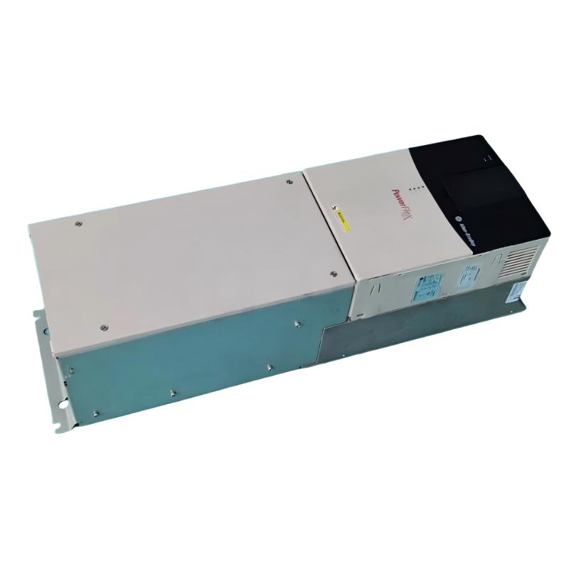
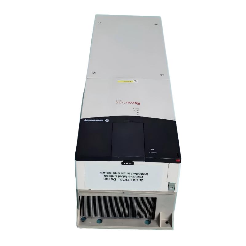
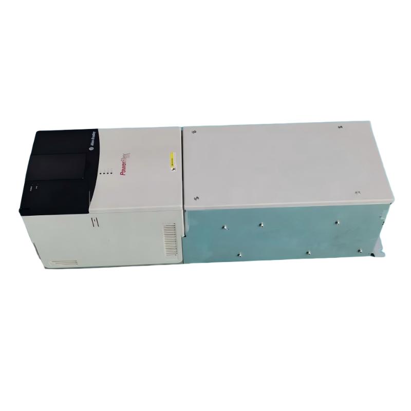
- Allen Bradley
- 20BD180A0ANNANC0NNAD
- PowerFlex AC Drive
- USA
- 850.0 × 403.9 × 275.5 mm
- 71.44kg
- Xiamen, China
- New & In Stock
- T/T, PayPal, Western Union
- 1 Year
- 1-3 Working Days
- DHL, UPS, TNT, FedEx and EMS.
- 24-Hour Service
- COO
- 3
Our advantage

Global Logistics
We have a 10-year logistics and express cooperation agreement, so our products can be shipped to any place in the world.

Brand new and original
Our products are imported in bulk from the place of origin. Because of the cooperative relationship, our products are all original and 100% new.

24-hour service
We provide 7*24 hours service to our customers. We will be there whenever you need us.

Price advantage
All our products are priced very favorably because we have our own warehouse and supply.
| Company Information | |||
| [email protected] | |||
| Mobile | +8615980777398 | ||
| +8615980777398 | |||
| 15980777398 |
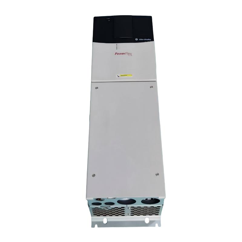
Allen-Bradley 20BD180A0ANNANC0NNAD AC Drive: Product Description, Technical Parameters, Applications, Advantages, and Related Models
1. Product Overview
The Allen-Bradley 20BD180A0ANNANC0NNAD is a catalog number associated with the PowerFlex 700 family of industrial variable-frequency AC drives. This product family is designed to regulate the speed and torque of three-phase AC motors in industrial machinery, manufacturing equipment, and automated processes.
An AC drive controls motor operation by adjusting the frequency and voltage delivered to the motor. Instead of running continuously at a fixed speed, the motor can operate at different speeds according to process demand. This helps equipment achieve controlled acceleration, adjustable production speed, and smoother stopping.
The model number provided is longer than the base catalog number 20BD180A0ANNANC0. The additional NNAD suffix may identify a further configuration or option, so it should not be assumed that every specification of the base model applies unchanged to the full catalog number. The complete nameplate and option code are important when ordering a replacement, choosing accessories, or planning a control-system upgrade.
The PowerFlex 700 family includes drives for demanding industrial applications where current capacity, overload performance, motor-control behavior, and integration with external controls are important. For this particular catalog number, the voltage class and output rating should be confirmed against the drive nameplate before final engineering or procurement.
2. Brand and Product Series
|
Item |
Details |
|---|---|
|
Brand |
Allen-Bradley |
|
Product series |
PowerFlex 700 |
|
Product category |
Industrial AC drive / variable-frequency drive |
|
Full model supplied |
|
|
Base catalog number for comparison |
20BD180A0ANNANC0 |
|
Rated supply voltage class |
480 V AC |
|
Input power supply |
Three-phase |
|
Normal-duty output current |
180 A |
|
Normal-duty motor rating |
150 HP |
|
Heavy-duty motor rating |
125 HP |
|
Enclosure class |
IP20 / NEMA Type 1 |
|
Control type |
Standard control; vector-control capabilities depend on configuration |
|
Human interface |
Blank front-panel configuration on the base model |
|
Communication option |
Must be confirmed for the complete catalog number |
|
Feedback option |
No feedback option specified for the base configuration |
|
Braking |
No internal brake resistor or brake IGBT specified for the base configuration |
|
Lifecycle status |
PowerFlex 700 20B family discontinued |
|
Typical installation |
Industrial electrical cabinet or suitable protected equipment area |
Catalog-number clarification: The complete number 20BD180A0ANNANC0NNAD could not be matched confidently to a distinct standard configuration. The electrical specifications below therefore describe the closely matching base model 20BD180A0ANNANC0, not a verified independent specification sheet for every character in the longer number. Before ordering, confirm the entire number on the product nameplate, including any option or assembly suffix.
3. Detailed Technical Specifications
3.1 Electrical Parameters
|
Parameter |
Specification |
|---|---|
|
Model under evaluation |
20BD180A0ANNANC0NNAD |
|
Comparable base model |
20BD180A0ANNANC0 |
|
Drive family |
PowerFlex 700 |
|
Rated input voltage |
480 V AC |
|
Input phase |
3-phase |
|
Nominal line frequency |
60 Hz |
|
Input current |
169 A at 480 V AC, 3-phase |
|
Input apparent power |
141 kVA at 480 V AC |
|
Normal-duty output current |
180 A continuous |
|
Normal-duty motor power |
150 HP |
|
Heavy-duty motor power |
125 HP |
|
Output phase |
3-phase |
|
Output voltage range |
0 to rated motor voltage |
|
Maximum output voltage |
Up to approximately 460 V AC with a 480 V-class supply |
|
Standard-control output frequency |
0–400 Hz |
|
Vector-control output frequency |
Up to 420 Hz, depending on configuration |
|
Carrier frequency |
2, 4, 8, or 10 kHz |
|
Rated carrier-frequency basis |
4 kHz |
|
Control methods |
Sensorless vector, V/Hz and vector-control options, depending on configuration |
|
Current-limit adjustment |
Programmable, approximately 20–160% of rated output current |
|
Acceleration and deceleration |
Two independently programmable ramps |
|
Programmable ramp time |
0–3600 seconds |
|
Ramp-time adjustment |
0.1-second increments |
|
Analog inputs |
2 |
|
Analog outputs |
2 |
|
Digital inputs |
6 |
|
Digital outputs |
3 |
|
Input power factor |
Approximately 0.98 displacement power factor |
|
Typical rated-load efficiency |
Approximately 97.5% |
|
Internal brake resistor |
No |
|
Brake IGBT |
No |
|
Feedback option |
None specified for the base configuration |
|
Internal EMC filter |
EMC filter with common-mode choke |
|
Internal communication module |
Must be confirmed for the full catalog number |
|
Enclosure |
IP20 / NEMA Type 1 |
3.2 Overload, Protection, and Operating Parameters
|
Parameter |
Specification |
|---|---|
|
Normal-duty continuous output current |
180 A |
|
Heavy-duty overload, 1 minute |
Approximately 234 A |
|
Heavy-duty overload, 3 seconds |
Approximately 312 A |
|
AC input overvoltage trip |
Approximately 570 V AC for the 480 V class |
|
AC input undervoltage trip |
Approximately 280 V AC for the 480 V class |
|
DC bus nominal voltage |
Approximately 648 V DC |
|
DC bus overvoltage trip |
Approximately 810 V DC |
|
DC bus undervoltage shutdown |
Approximately 305 V DC |
|
Instantaneous overcurrent trip |
Approximately 220–300% of rated current, depending on drive rating |
|
Maximum short-circuit rating |
Up to 200,000 A symmetrical, subject to the required protective-device and installation conditions |
|
Motor overload protection |
Available through supported drive protection functions; settings depend on the exact control configuration |
|
Programmable stop modes |
Coast, DC braking, fast braking, ramp-to-stop, and other supported modes |
|
Logic control ride-through |
Approximately 0.5 second minimum and 2 seconds typical, depending on conditions |
|
Full-power voltage range |
Approximately 460–528 V for the relevant 380–480 V drive class |
|
Operating voltage range |
Approximately 342–528 V for the relevant 380–480 V drive class |
|
Ambient operating temperature |
Typically 0–50°C for applicable IP20 frames and ratings, subject to derating |
|
Maximum altitude without derating |
Approximately 1,000 m |
|
Relative humidity |
5–95%, non-condensing |
|
Storage temperature |
Down to approximately −40°C |
|
Enclosure suitability |
Protected indoor installation; not intended for direct exposure to water or conductive contamination |
The drive’s overload figures are dependent on the selected duty rating and operating conditions. They should not be interpreted as continuous output ratings. The final settings must match the motor’s nameplate current, the machine’s load profile, the required acceleration and stopping behavior, and the applicable installation instructions.
3.3 Physical Dimensions and Weight
The comparable 180 A IP20 drive has the following physical dimensions. These figures are useful for preliminary planning, but the complete catalog number should be checked before a replacement is ordered.
|
Physical parameter |
Specification |
|---|---|
|
Model |
20BD180A0ANNANC0NNAD |
|
Reference configuration |
PowerFlex 700, 180 A, IP20 / NEMA Type 1 |
|
Drive height, including mounting hardware |
Approximately 850.0 mm |
|
Drive width, including mounting hardware |
Approximately 403.9 mm |
|
Drive depth |
Approximately 275.5 mm |
|
Mounting-hole width |
Approximately 300.0 mm |
|
Mounting-hole height |
Approximately 825.0 mm |
|
Approximate drive net weight |
71.44 kg |
|
Approximate packaged weight |
100.9 kg |
|
Separate IP54/NEMA Type 12 standalone assembly height |
Approximately 1828.8 mm |
|
Separate IP54/NEMA Type 12 standalone assembly width |
Approximately 711.3 mm |
|
Separate IP54/NEMA Type 12 standalone assembly depth |
Approximately 487.8 mm |
|
Separate IP54 standalone assembly weight |
Approximately 229.07 kg, including drive and packaging |
|
Mounting orientation |
Follow the applicable dimensional drawing |
|
Cooling requirements |
Maintain required ventilation clearances and airflow |
Important: The dimensions of the separate IP54/NEMA Type 12 standalone assembly are not the dimensions of the standard IP20 drive alone. The 229.07 kg figure also refers to that larger assembly and its packaging. For the comparable IP20 unit, the drive weight is approximately 71.44 kg; confirm the exact weight and mechanical drawing for the full catalog number before making a purchase or planning freight.
4. Product Introduction
The PowerFlex 700 is an industrial variable-frequency drive family designed to control AC motor speed and torque in production and process equipment. It is intended for applications where motor operation needs to be adjusted to suit changing production conditions rather than running continuously at one fixed speed.
The 20BD180A0ANNANC0NNAD, evaluated against its closely matching base configuration, is in the 480 V, three-phase, 180 A class. Its comparable base model carries a 150 HP normal-duty rating and a 125 HP heavy-duty rating. This places it in the higher-power range of industrial motor drives used in production lines, material handling and process machinery.
One of the principal functions of an AC drive is to regulate motor speed by changing the output frequency. In a pump system, for example, this allows the motor to respond to changing flow demand. In a conveyor system, it allows the belt to run at different speeds and start more gradually. In industrial processing equipment, it can help the motor maintain a more suitable operating speed as the load changes.
The PowerFlex 700 family also supports programmable acceleration and deceleration, motor-control adjustments, monitoring and protective functions. These features help equipment designers tailor drive behavior to the actual machinery. The final control performance depends on the drive’s precise configuration, motor characteristics, parameter settings and whether external feedback is required.
The base configuration is designed for a protected installation. Its IP20/NEMA Type 1 enclosure is normally installed inside a suitable electrical cabinet or equipment room. It should not be treated as a washdown or outdoor drive without an appropriately rated enclosure and suitable environmental protection.
The full catalog number supplied includes additional characters beyond the base number. Those characters should be verified before assuming that the drive includes a particular network module, I/O voltage, feedback option, braking function or other accessory. Such differences can affect both system compatibility and replacement cost.
5. Main Product Advantages
5.1 High Current Capacity for Industrial Motors
The comparable base model provides 180 A of continuous normal-duty output current. This capacity can support substantial industrial motor loads when the motor current, supply voltage and application duty fall within the drive’s permitted operating range.
A drive should not be selected by horsepower alone. Motor full-load current, starting torque, overload duration, load inertia and the operating environment all influence the correct choice. A suitable current rating helps the motor operate within the intended limits and reduces the risk of nuisance trips caused by an undersized drive.
5.2 Adjustable Motor Speed
The drive can vary the motor’s operating speed according to the process requirement. This is useful where a machine needs different production speeds, controlled feed rates, variable pumping capacity or adjustable airflow.
By matching motor speed to actual demand, a drive may also reduce unnecessary energy consumption in suitable variable-torque applications. The level of savings depends on the load, the operating schedule and the efficiency of the complete system.
5.3 Controlled Acceleration and Deceleration
Programmable acceleration and deceleration allow the motor to reach operating speed more gradually and stop in a controlled manner. This can reduce sudden mechanical stress on belts, couplings, gearboxes, shafts and transported products.
For machines with high inertia, however, the ramp time must be selected carefully. A short deceleration ramp may produce excessive DC-bus voltage or require a braking solution. A very long ramp may slow production or fail to meet process requirements.
5.4 Flexible Motor-Control Methods
The PowerFlex 700 family supports different motor-control approaches, including V/Hz and vector-control methods, depending on the drive configuration. V/Hz control is suitable for many general-purpose applications, while vector control can provide improved speed and torque response in more demanding applications.
The best control method depends on the motor, the required speed range, the load behavior and whether encoder feedback is necessary. A configuration without feedback should not be assumed to provide the same behavior as a feedback-equipped drive in applications requiring precise low-speed control or synchronization.
5.5 Programmable Protection and Monitoring
Drive protection functions can help detect abnormal operating conditions and prevent continued operation when configured limits are exceeded. Available functions and their behavior depend on the installed control configuration and parameter settings.
Appropriate setup requires correct motor data, current limits, acceleration and deceleration times, thermal protection settings and coordination with upstream circuit protection. A drive’s built-in functions do not replace required machine-safety circuits or electrical isolation procedures.
5.6 Flexible Integration with Industrial Control Systems
The PowerFlex 700 family supports integration with external control systems through its I/O and compatible communications options. Analog signals can be used for speed references or process feedback, while digital inputs and outputs can support start, stop, status and interlock functions.
The precise interface must be confirmed for the full model number. In particular, control voltage, communication modules and feedback options must match the PLC, sensors, operator controls and existing wiring.
5.7 Industrial Construction and Cabinet Installation
The IP20/NEMA Type 1 configuration is suited to protected industrial installations. A properly designed panel can provide environmental protection, organized wiring, cooling airflow and access for maintenance.
For a replacement installation, the frame dimensions, mounting holes, cable routing, ventilation clearances and service access should be checked against the physical unit. Even drives with similar electrical ratings may differ in mechanical layout or option placement.
5.8 Support for Established Industrial Equipment
Where the PowerFlex 700 is already integrated into a machine, maintaining the same drive family may help reduce the engineering work associated with control wiring, parameters and maintenance procedures. This advantage is strongest when the replacement configuration matches the existing hardware and firmware requirements.
Because the PowerFlex 700 20B family is discontinued, continued use or replacement should also take lifecycle support into account. Availability of compatible hardware, repair services, spare parts and long-term maintenance resources should be evaluated before committing to a large-scale deployment.
6. Typical Applications
6.1 Conveyor and Material-Handling Systems
Conveyors often require smooth starts and stops to prevent products from slipping, tipping or accumulating unevenly. A suitably rated PowerFlex 700 drive can provide adjustable belt speed and controlled acceleration.
For large conveyors, the engineering assessment should include starting torque, loaded-start requirements, belt tension, gearbox ratings and the consequences of stopping under load. If the conveyor includes a vertical section or high-inertia load, braking and safety requirements need additional attention.
6.2 Pumps and Water-Handling Equipment
A variable-frequency drive can adjust pump speed to match flow demand. In appropriate centrifugal-pump systems, operating at a lower speed may reduce energy consumption compared with running continuously at full speed and controlling flow solely through throttling.
The selection must consider pump type, required pressure, minimum flow, motor cooling, seal requirements and the risk of operating outside the pump’s permitted range. The drive’s current rating must also be compatible with the motor’s actual full-load current.
6.3 Fans and Ventilation Systems
Industrial fans and ventilation equipment often operate under changing demand. Adjustable motor speed can help regulate airflow and maintain a more suitable operating point.
For variable-torque fan loads, reducing speed can offer meaningful energy savings. The expected result depends on the fan curve, duct resistance, operating schedule and system design. The motor and fan must remain within their acceptable speed range.
6.4 Mixers and Agitators
Mixing processes may require different speeds during charging, blending, holding and unloading. A drive allows the operator or control system to select appropriate speed settings and acceleration profiles.
The required torque can vary substantially with the viscosity and quantity of the material. The motor and drive should therefore be selected based on the most demanding operating condition rather than the average load alone.
6.5 Industrial Production Lines
Production lines may use adjustable-speed drives on feed mechanisms, transfer conveyors, process equipment and auxiliary machinery. A drive can help coordinate speed changes with upstream and downstream equipment.
If the process requires synchronization between multiple motors, encoder feedback or network-based coordination, the exact drive configuration must be reviewed. The base catalog number alone does not confirm that every required communication or feedback option is installed.
6.6 General-Purpose Industrial Machinery
The drive may be considered for other three-phase AC motor applications where its voltage, current, overload capacity, control interface and enclosure rating are suitable.
Before final selection, confirm the machine’s load type, operating duty, required stopping time, ambient conditions, cable length, control architecture and safety requirements. These details are essential to determining whether the drive is appropriate for the application.
7. Five Related Models in the Same Series or Product Family
The following models provide useful comparison points within the PowerFlex 700 family. Their catalog-number suffixes indicate different configurations, so their specifications should not be assumed to be identical.
|
Model |
Series |
Main parameters |
Dimensions and weight |
|---|---|---|---|
|
20BD180A0ANNANC0 |
PowerFlex 700 |
480 V AC, 3-phase, 180 A, 150 HP normal duty, 125 HP heavy duty, IP20 / Type 1 |
Approximately 850.0 × 403.9 × 275.5 mm (H × W × D); approximately 71.44 kg for the comparable IP20 unit |
|
20BD180A0ANNAND0 |
PowerFlex 700 |
480 V AC, 3-phase, 180 A, 150 HP normal duty, 125 HP heavy duty; verify control and option details |
Approximately 850.0 × 403.9 × 275.5 mm; approximately 71.44 kg for the comparable IP20 unit |
|
20BD180A0ANNACA0 |
PowerFlex 700 |
480 V AC, 3-phase, 180 A, 150 HP normal duty, 125 HP heavy duty; ControlNet coaxial option and 24 V I/O in the listed configuration |
Comparable Frame 6 IP20 dimensions approximately 850.0 × 403.9 × 275.5 mm; approximately 71.44 kg, subject to exact configuration |
|
20BD156A3ANNAND0 |
PowerFlex 700 |
480 V-class, 3-phase, 156 A class, approximately 125 HP normal duty; confirm all option details |
Confirm exact drawing; weight may vary with configuration |
|
20BD156A3ANNACA0 |
PowerFlex 700 |
480 V-class, 3-phase, 156 A class, alternate option configuration; verify I/O and communications |
Confirm exact drawing; weight may vary with configuration |
Related-Model Selection Notes
– For the closest electrical match: Compare the 180 A PowerFlex 700 variants first. The output-current rating and normal-duty power rating are important starting points, but they do not guarantee that the control interfaces are interchangeable.
– For a different communications requirement: The ControlNet-equipped configuration may be relevant where the installed control architecture requires that interface. Verify the controller, network arrangement and exact module configuration before selecting it.
– For a lower-current alternative: The 156 A models may be worth evaluating only if the motor’s rated current, overload requirements and load profile allow the lower rating.
– For a direct replacement: Match the complete catalog number, control voltage, feedback configuration, communications, braking features, mounting arrangement and parameter requirements. Do not choose solely on the basis of horsepower.
8. Five Other Popular Models from the Same Brand
The following models represent other industrial AC-drive options within the same brand portfolio. They cover smaller motor applications and larger industrial drive families, so they are alternatives for evaluation rather than direct substitutes for a 180 A PowerFlex 700.
|
Model |
Series |
Main parameters |
Dimensions and weight |
|---|---|---|---|
|
25B-D6P0N104 |
PowerFlex 525 |
480 V-class compact drive; approximately 6 A output-current class; intended for smaller motor applications |
Compact-frame dimensions and weight; confirm the exact model drawing |
|
25B-D010N104 |
PowerFlex 525 |
480 V-class compact drive; approximately 10 A output-current class; adjustable-speed motor control |
Compact-frame dimensions and weight; confirm the exact model drawing |
|
25B-D017N104 |
PowerFlex 525 |
480 V-class compact drive; approximately 17 A output-current class; for compatible smaller industrial motors |
Compact-frame dimensions and weight; confirm the exact model drawing |
|
20F1ANC170JA0NNNNN |
PowerFlex 753 |
PowerFlex 750-series industrial drive; higher-power control platform; exact voltage, current and options require confirmation |
Frame-dependent; confirm the complete catalog number and dimensional drawing |
|
20G1ANC260JA0NNNNN |
PowerFlex 755 |
PowerFlex 750-series industrial drive; advanced industrial motor-control family; exact rating and options require confirmation |
Frame-dependent; confirm the complete catalog number and dimensional drawing |
Important selection point: The PowerFlex 525 models are generally for much smaller motors than the 180 A PowerFlex 700. The PowerFlex 753 and PowerFlex 755 families are more relevant when evaluating a modernization of a larger industrial drive, but their actual suitability depends on the exact voltage, output-current rating, overload capacity, feedback, communications and braking requirements.
The dimensions and weights of these five models are intentionally not estimated from horsepower or family name alone. Physical size can change with frame, voltage class, enclosure, filtering, braking and installed options. For a purchase specification, use the dimensional drawing and weight for the exact catalog number.
9. Comparison of the Target Model and Similar PowerFlex 700 Drives
|
Comparison item |
20BD180A0ANNANC0NNAD |
20BD180A0ANNANC0 |
20BD180A0ANNAND0 |
20BD156A3ANNAND0 |
|---|---|---|---|---|
|
Product family |
PowerFlex 700, subject to catalog confirmation |
PowerFlex 700 |
PowerFlex 700 |
PowerFlex 700 |
|
Voltage class |
Confirm against nameplate |
480 V AC |
480 V AC |
480 V class |
|
Normal-duty output current |
Confirm against full model |
180 A |
180 A |
156 A class |
|
Normal-duty power |
Confirm against full model |
150 HP |
150 HP |
Approximately 125 HP |
|
Heavy-duty power |
Confirm against full model |
125 HP |
125 HP |
Confirm exact configuration |
|
Enclosure |
Confirm full configuration |
IP20 / Type 1 |
IP20 / Type 1 |
Confirm exact configuration |
|
I/O voltage |
Confirm full configuration |
Verify unit-specific configuration |
Verify unit-specific configuration |
Verify unit-specific configuration |
|
Communications |
Confirm full configuration |
Confirm installed options |
Confirm installed options |
Confirm installed options |
|
Brake IGBT |
Confirm full configuration |
No for the base configuration |
Confirm unit-specific configuration |
Confirm unit-specific configuration |
|
Internal brake resistor |
Confirm full configuration |
No for the base configuration |
Confirm unit-specific configuration |
Confirm unit-specific configuration |
|
Approximate IP20 dimensions |
Must be confirmed |
850.0 × 403.9 × 275.5 mm |
850.0 × 403.9 × 275.5 mm |
Confirm exact drawing |
|
Approximate IP20 drive weight |
Must be confirmed |
71.44 kg for the comparable configuration |
Approximately 71.44 kg for the comparable configuration |
Confirm exact unit |
10. Installation and Commissioning Considerations
10.1 Power Supply and Protection
Confirm that the available supply matches the drive’s voltage and phase requirements. The upstream circuit protection must be selected in accordance with the applicable drive instructions, electrical code and available fault current.
Grounding, cable routing, conductor sizing and separation between power and control wiring should follow the installation requirements. Incorrect grounding or wiring can cause nuisance trips, electrical interference or equipment damage.
10.2 Motor Selection and Configuration
Check the motor’s rated voltage, full-load current, horsepower, base frequency, speed range and operating duty. Enter the motor nameplate information correctly during commissioning.
The drive’s normal-duty rating should not be treated as an unlimited guarantee of motor capacity. The machine’s actual load and overload profile determine whether the selected current rating is suitable.
10.3 Panel Layout and Cooling
The IP20 drive must be installed in a suitable protected environment. Provide the required clearance around the unit and account for heat loss, ambient temperature, ventilation, cable bending radius and maintenance access.
The comparable IP20 drive measures approximately 850.0 mm high, 403.9 mm wide and 275.5 mm deep. These dimensions should be treated as preliminary until confirmed for the exact full catalog number.
10.4 Control Interface
Check the drive’s I/O voltage and terminal configuration before connecting PLC outputs, relays, pushbuttons or external interlocks. The base model and related variants may have different control options.
If the machine uses network-based commands or remote monitoring, confirm which communication module is actually installed. A similar model number does not prove that the same interface is present.
10.5 Braking and High-Inertia Loads
The comparable base configuration does not include an internal brake resistor or brake IGBT. If the machine needs rapid deceleration, handles a high-inertia load or moves a vertical load, a suitable braking arrangement may be required.
The braking system should be engineered for the load’s regenerative energy and duty cycle. Vertical motion and other hazardous applications may also require independent mechanical holding and safety provisions.
10.6 Environmental Conditions
Confirm that the installation environment meets the drive’s temperature, humidity, altitude and contamination requirements. IP20/NEMA Type 1 is intended for a protected installation and is not equivalent to a sealed washdown enclosure.
If the environment contains conductive dust, corrosive vapors or moisture, additional enclosure protection and a review of the installation design may be necessary.
10.7 Lifecycle and Maintenance
The PowerFlex 700 20B family is discontinued. For an existing installation, assess the condition of the drive, availability of replacement hardware, repair options, spare parts and the consequences of unexpected downtime.
Before removing a working drive, record its parameters, wiring, communication settings and fault history where possible. A replacement should be commissioned under controlled conditions, with protective functions and machine interlocks tested before normal production resumes.
11. Product Summary
The Allen-Bradley 20BD180A0ANNANC0NNAD is best evaluated as a PowerFlex 700-related industrial AC drive with a closely matching 180 A base configuration. The comparable base model is rated at 480 V AC, three-phase, 180 A output current, 150 HP normal duty and 125 HP heavy duty.
Its principal strengths are adjustable motor speed, programmable acceleration and deceleration, industrial motor-control capabilities, and the ability to support a variety of production and process applications. These features can help improve operating flexibility and reduce unnecessary mechanical stress when the drive is correctly selected and commissioned.
The most important qualification is the complete catalog number. The longer model number supplied could not be confidently verified as a separate standard configuration. For that reason, the base-model specifications should be used as a technical comparison, not as final confirmation of every installed option.
For a direct replacement, confirm the full nameplate number, input voltage, output current, I/O voltage, communication module, braking configuration, dimensions and net weight. For a modernization, compare the PowerFlex 700 with an appropriate newer drive only after checking the motor, load, controls, safety requirements and cabinet layout.
Recommended engineering approach: Treat the 180 A PowerFlex 700 as the reference point, verify the complete catalog number, and select the final replacement according to actual motor current and duty rather than horsepower alone.