

ProductPRODUCT
Featured products
Contact Us
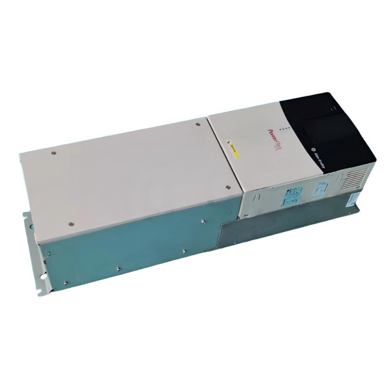
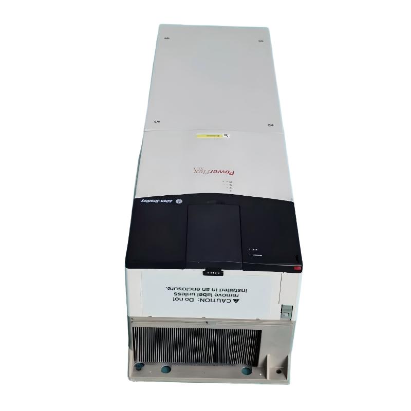
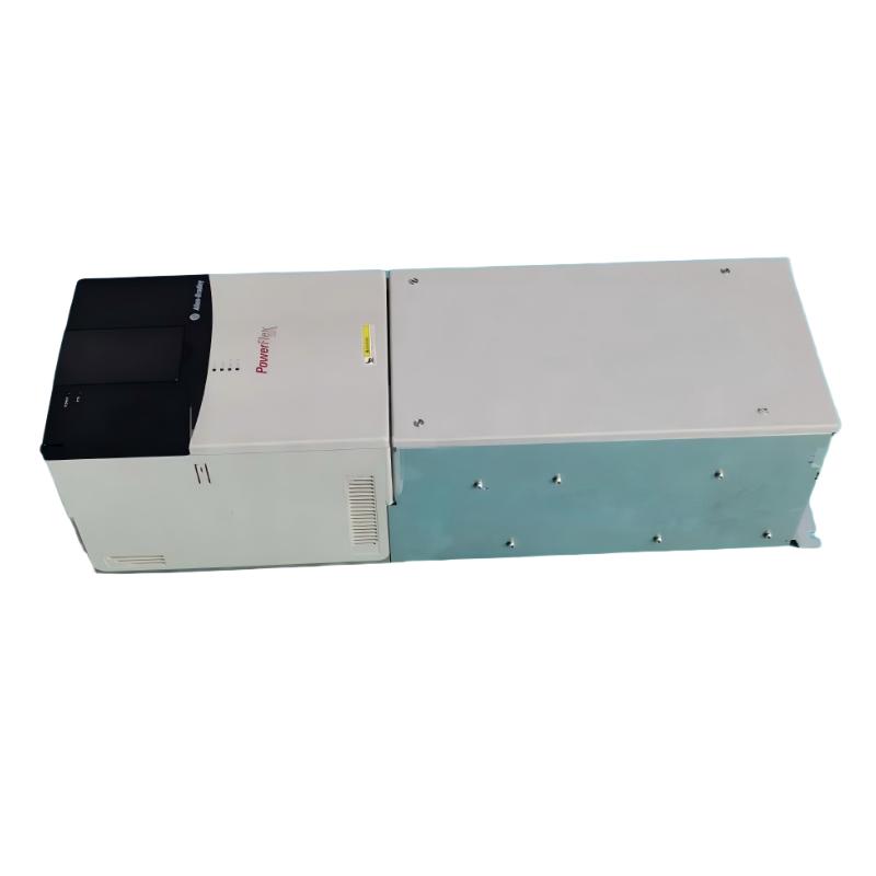
- Allen Bradley
- 20BC170A3ANNANA0
- PowerFlex AC Drive
- USA
- 1,828.8 × 711.3 × 487.8 mm
- 229.07kg
- Xiamen, China
- New & In Stock
- T/T, PayPal, Western Union
- 1 Year
- 1-3 Working Days
- DHL, UPS, TNT, FedEx and EMS.
- 24-Hour Service
- COO
- 2
Our advantage

Global Logistics
We have a 10-year logistics and express cooperation agreement, so our products can be shipped to any place in the world.

Brand new and original
Our products are imported in bulk from the place of origin. Because of the cooperative relationship, our products are all original and 100% new.

24-hour service
We provide 7*24 hours service to our customers. We will be there whenever you need us.

Price advantage
All our products are priced very favorably because we have our own warehouse and supply.
| Company Information | |||
| [email protected] | |||
| Mobile | +8615980777398 | ||
| +8615980777398 | |||
| 15980777398 |
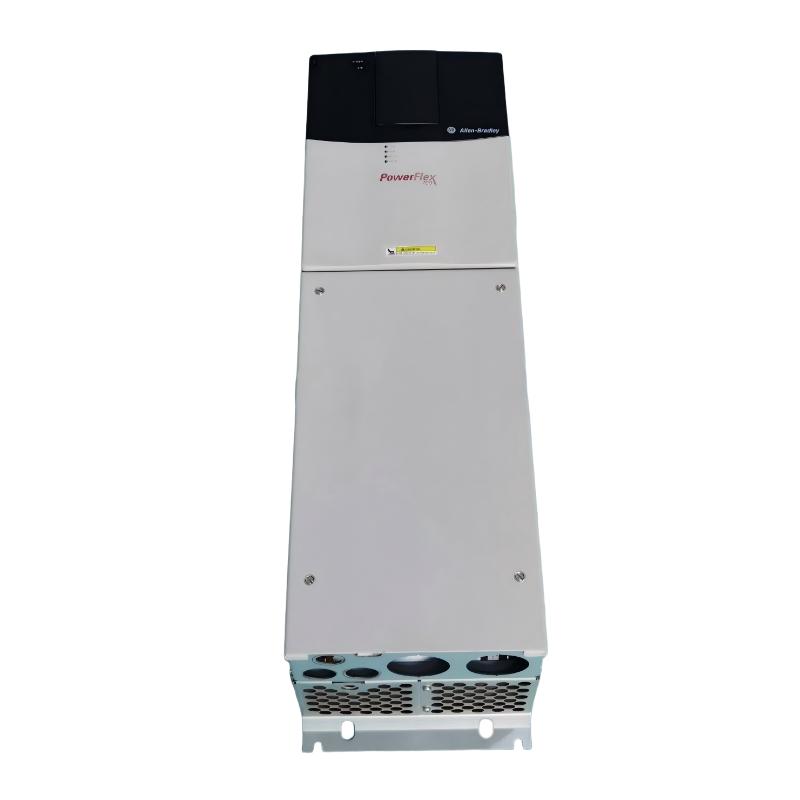
Allen-Bradley 20BC170A3ANNANA0 AC Drive: Technical Specifications, Product Overview, Applications, Advantages, and Recommended Models
1. Product Overview
The Allen-Bradley 20BC170A3ANNANA0 is a catalog-number configuration associated with the PowerFlex 700 family of industrial AC drives. This type of variable-frequency drive is designed to regulate the speed and operation of three-phase AC motors in industrial machinery, production equipment, and automated process systems.
An industrial AC drive controls motor operation by adjusting the frequency and voltage supplied to the motor. This enables machinery to start gradually, operate at a selected speed, and decelerate according to process requirements rather than running continuously at a fixed speed.
The PowerFlex 700 family is intended for applications requiring adjustable motor speed, industrial control integration, and configurable motor-control functions. Depending on the specific configuration, these drives can support applications involving conveyors, pumps, fans, mixers, material-handling equipment, and general manufacturing machinery.
The exact catalog number is important because the letters and numbers in a drive’s designation can identify differences in voltage class, current rating, enclosure, communication options, filtering, and other hardware features. The suffix NANA0 should not be interpreted as a complete description of every installed option without confirming the product’s configuration.
This description is intended for technical evaluation, equipment documentation, and preliminary model comparison. No live product lookup is being used, so unconfirmed factory specifications are identified rather than presented as guaranteed values.
2. Basic Product Identification
|
Parameter |
Product Details |
|---|---|
|
Model |
|
|
Brand |
Allen-Bradley |
|
Product series |
PowerFlex 700 |
|
Product category |
Industrial variable-frequency AC drive |
|
Equipment type |
Adjustable-frequency motor controller |
|
Primary function |
Control of AC motor speed, acceleration, and deceleration |
|
Typical power supply |
Three-phase industrial AC supply; confirm the nameplate |
|
Intended application |
Industrial machinery and automated production equipment |
|
Motor type |
Compatible three-phase AC motors, subject to the drive’s ratings |
|
Control functions |
Configurable motor control, speed references, and operating commands |
|
Installation environment |
Industrial electrical panel or approved enclosure |
|
Control integration |
Local control and supported external automation interfaces |
|
Product configuration |
Exact option configuration must be confirmed from the complete catalog number |
|
Dimensions |
Exact mechanical drawing required for confirmation |
|
Weight (kg) |
Exact catalog-specific net weight requires confirmation |
|
Replacement suitability |
Depends on electrical ratings, options, enclosure, and application requirements |
The most important distinction is between the product family and the exact catalog configuration. Two drives may both belong to the PowerFlex 700 family but differ in communication interfaces, enclosure arrangements, feedback hardware, or other options.
For maintenance and procurement purposes, the full catalog number should always be recorded exactly as shown on the drive nameplate.
3. Detailed Technical Specifications
The 20BC170A3ANNANA0 should be evaluated as a 400 V-class, 170 A PowerFlex 700 drive configuration. The A3 portion of the catalog number is particularly important when checking the enclosure and mechanical arrangement. A standalone enclosed drive can occupy substantially more space and weigh considerably more than an open-panel version of the same electrical rating.
The table below gives the principal electrical ratings associated with this drive class and identifies the mechanical information that needs to be matched to the exact enclosure configuration.
|
Parameter |
Technical specification |
|---|---|
|
Model |
20BC170A3ANNANA0 |
|
Brand |
Allen-Bradley |
|
Product series |
PowerFlex 700 |
|
Drive type |
Variable-frequency AC drive |
|
Nominal supply voltage |
400 V AC |
|
Input voltage class |
380–480 V AC |
|
Input phase |
Three-phase |
|
Output phase |
Three-phase |
|
Supply frequency |
50 Hz nominal |
|
Continuous output current |
170 A, normal-duty rating |
|
Normal-duty motor power |
Approximately 90 kW |
|
Heavy-duty motor power |
Approximately 75 kW |
|
Heavy-duty current |
Verify the applicable rating table and duty classification |
|
Maximum output frequency |
Up to 400 Hz for the referenced configuration; verify the exact configuration |
|
Output voltage |
Variable, up to the applicable rated motor voltage |
|
Control method |
Standard motor control; confirm the installed control configuration |
|
Analog inputs |
2 |
|
Analog outputs |
2 |
|
Digital inputs |
6 |
|
Digital outputs |
3 |
|
Operator interface |
Configuration-dependent; verify whether a keypad or blank interface plate is fitted |
|
Internal braking resistor |
Not assumed to be fitted |
|
Brake IGBT |
Verify the exact catalog configuration |
|
Communication module |
Verify the exact catalog configuration |
|
Feedback |
Verify whether encoder feedback hardware is installed |
|
Enclosure protection |
Confirm the exact standalone enclosure and IP rating |
|
Operating temperature |
Application and enclosure dependent; thermal derating may apply |
|
Maximum altitude without derating |
Approximately 1,000 m under applicable rated conditions |
|
Relative humidity |
5–95%, non-condensing |
|
Dimensions (H × W × D) |
Approx. 1,828.8 × 711.3 × 487.8 mm for the associated standalone enclosure configuration; confirm the exact drawing |
|
Weight (kg) |
Approx. 229.07 kg for the associated standalone drive and packaging configuration; confirm the net equipment weight separately |
3.1 Electrical Ratings and Motor Compatibility
The 170 A continuous output rating is a key selection parameter. It determines the range of motor loads that can be supported under the specified operating conditions.
The approximately 90 kW normal-duty and 75 kW heavy-duty classifications represent different application requirements. Normal-duty applications generally allow a higher motor power rating where the load profile and overload demand permit it. Heavy-duty applications require more consideration of starting torque, transient loading, and sustained overload requirements.
The motor’s nameplate current should be checked before selecting the drive. Two motors with similar power ratings can have different current requirements because of differences in voltage, efficiency, power factor, and operating conditions.
3.2 Control Configuration
The drive’s control configuration affects how it receives commands, processes speed references, and interacts with the machine controller.
Digital inputs can be used for functions such as start, stop, direction selection, reset, and preset-speed selection, depending on the programmed configuration. Analog inputs can accept suitable speed or process references, while analog outputs can provide selected operating information to external equipment.
The exact control arrangement should be established from the terminal configuration and the existing electrical drawings. An identical current rating does not guarantee identical control functionality.
3.3 Enclosure and Mechanical Arrangement
The mechanical arrangement is particularly important for the A3 catalog configuration. A standalone enclosure can be much larger than the drive chassis itself because it accommodates power terminals, control components, cooling provisions, and protective housing.
The approximate standalone dimensions of 1,828.8 mm high, 711.3 mm wide, and 487.8 mm deep are useful for preliminary space planning when applicable to the installed configuration. The associated approximate weight of 229.07 kg includes the drive and packaging in the referenced mechanical specification, so it should not automatically be treated as the net installed weight.
For lifting, mounting, transportation, and floor-loading calculations, use the exact mechanical drawing and the manufacturer’s stated net and shipping weights for the complete catalog number.
3.4 Environmental Requirements
The installation environment affects the reliability of the drive. Temperature, ventilation, dust, moisture, vibration, and altitude can influence cooling performance and allowable output current.
The drive should be installed in the enclosure arrangement for which it was designed. Any modification to ventilation, cooling airflow, or protective housing should be evaluated before operation.
The drive must also be installed with suitable grounding, branch-circuit protection, motor cabling, and isolation provisions. Its built-in fault protection does not replace the protective equipment required for the complete electrical installation.
4. Product Introduction
The Allen-Bradley 20BC170A3ANNANA0 is intended for industrial motor-control systems where a large three-phase AC motor needs adjustable speed and controlled operation.
In a conventional fixed-speed installation, the motor operates at a speed largely determined by the supply frequency and motor characteristics. A variable-frequency drive changes the electrical frequency supplied to the motor, allowing the machine to operate at different speeds according to process requirements.
This capability is valuable in industrial environments where the load changes during operation. A conveyor may need to accelerate gradually as production begins, a fan may need to adjust airflow throughout the day, and a pump may need to maintain a target flow or pressure as process demand changes.
The PowerFlex 700 family provides a platform for controlling motor operation and integrating drive functions into an industrial automation system. Depending on the hardware and configuration, the drive may support local operating controls, external run commands, analog speed references, programmed ramps, fault monitoring, and communication with supervisory equipment.
The model’s high-current rating makes it relevant to substantial motor loads. Its suitability, however, depends on the actual motor, operating duty, control requirements, and enclosure configuration rather than the model number alone.
For maintenance teams, the complete catalog number is also important because it helps distinguish the installed equipment from other PowerFlex 700 drives with different control, feedback, braking, or communication options.
5. Product Applications
5.1 Industrial Conveyor Systems
Conveyor systems are common applications for variable-frequency drives because the speed of material movement often needs to be coordinated with other machinery.

The drive can provide gradual acceleration and deceleration, reducing sudden mechanical loading on belts, gearboxes, couplings, and driven rollers.
In production lines, adjustable speed can also help synchronize the movement of products between stations. Different speed references may be used for startup, normal production, and controlled stopping.
For heavily loaded conveyors, the motor and drive must be sized according to starting torque, load inertia, acceleration time, and the expected number of starts per hour.
5.2 Water Pumps and Industrial Pumping Systems

Pumping systems often operate under changing flow and pressure requirements. A drive can adjust motor speed to better match the required operating point.
In suitable centrifugal pump systems, reducing speed can lower energy consumption compared with maintaining a high constant speed and regulating flow through throttling alone. The actual benefit depends on the pump curve, static head, and process demand.
The application should also account for minimum flow, pressure limits, motor cooling, and the need for suitable protective interlocks.
5.3 Industrial Fans and Blowers

Industrial fans and blowers are used for ventilation, cooling, air circulation, and process exhaust. A variable-frequency drive allows airflow to be adjusted to operating requirements.
Gradual acceleration can reduce mechanical stress during startup, particularly where the fan has substantial inertia. Reduced-speed operation can also lower noise and energy consumption when the process permits it.
Selection should consider the fan’s inertia, required airflow, minimum operating speed, and the motor’s cooling requirements at reduced speed.
5.4 Mixers, Agitators, and Process Equipment
Mixers and agitators often need different speeds for different stages of a process. A drive can support controlled acceleration and adjustable operating speed.
This is useful when material viscosity changes during processing or when the mixing procedure requires different speeds for loading, mixing, and discharge.
The drive rating must be checked against the torque needed to start the equipment under its heaviest expected load. High-inertia machinery may also require careful deceleration programming and appropriate braking provisions.
5.5 Manufacturing and Production Machinery
Industrial production lines often combine several motors, sensors, programmable controllers, and operator interfaces.
A variable-frequency drive can provide adjustable motor speed and operating feedback to support the machine’s control sequence. This can help maintain repeatable production speeds and improve coordination between connected equipment.
The drive’s communication and I/O configuration must match the control system. A mismatch may require changes to wiring, programming, or network hardware even when the electrical ratings are suitable.
5.6 Material Processing and Heavy Industrial Machinery
Selected material-processing machines require substantial motor current and controlled speed changes. The 170 A drive class may be suitable where the motor rating, overload profile, and installation conditions fall within the applicable limits.
Potential applications include selected processing lines, industrial handling equipment, and mechanical auxiliary systems. Suitability must be determined from the actual load characteristics, not simply from the fact that the machine is industrial equipment.
6. Main Advantages of the 20BC170A3ANNANA0
6.1 Flexible Motor-Speed Adjustment
The drive allows motor speed to be adjusted according to the operating requirements of the machine. This is useful for production equipment that needs to operate at different speeds during startup, normal production, and shutdown.
Instead of relying entirely on mechanical speed-control methods, the control system can change the motor’s operating frequency to suit the process.
6.2 Controlled Starting and Stopping
Programmable acceleration and deceleration can help reduce sudden changes in mechanical loading.
This is particularly valuable for conveyor systems, large fans, pumps, and other machinery with significant rotating inertia. Appropriate ramp settings can reduce stress on connected components and improve the consistency of machine operation.
6.3 High-Current Industrial Motor Control
The 170 A continuous normal-duty rating makes this drive class suitable for substantial industrial motor loads when the motor and application fall within the specified operating limits.
The normal-duty and heavy-duty ratings allow engineers to evaluate the drive against different load profiles. The final selection should account for motor current, starting torque, overload duration, and operating temperature.
6.4 Configurable Control and I/O
The PowerFlex 700 platform supports configurable control functions and industrial I/O.
This allows the drive to be incorporated into systems using external start commands, speed references, interlocks, status signals, and process-control equipment. The actual control capabilities depend on the installed hardware and programming.
6.5 Industrial Fault Monitoring
Drive fault monitoring can help maintenance personnel identify electrical and operating problems. Depending on the configuration, protective functions may detect conditions such as overcurrent, bus overvoltage, undervoltage, and excessive temperature.
These features can assist with troubleshooting and reduce the time required to identify certain faults. They must be used alongside appropriate electrical protection and machine-safety measures.
6.6 Potential Energy Savings
In suitable pump and fan applications, reducing motor speed can lower energy consumption when the process does not require full output.
The energy benefit depends on the load profile and the mechanical characteristics of the system. A drive should not be assumed to produce the same savings in every application, particularly where the load requires approximately constant torque.
6.7 Suitability for Industrial Retrofits
When an existing machine already uses a PowerFlex 700 drive, retaining a compatible configuration can simplify certain parts of a maintenance or replacement project.
Existing wiring diagrams, parameter records, and control-system documentation may help with the work. Nevertheless, the replacement must be checked for electrical, mechanical, and control compatibility before installation.
7. Five Recommended Models from the Same Series or Related Configurations
The following five catalog numbers are useful candidates for comparison when evaluating the reference drive. They include related 170 A PowerFlex 700 configurations with different option arrangements.
The suffixes are important. A different suffix may indicate a change in communication, feedback, control method, or enclosure configuration. Therefore, these models should not be treated as interchangeable without an engineering check.
|
Model |
Series |
Main parameters |
Configuration differences to check |
Dimensions (H × W × D) |
Weight (kg) |
|---|---|---|---|---|---|
|
20BC170A3ANNANA0 |
PowerFlex 700 |
400 V AC class; 170 A normal duty; approximately 90 kW normal duty and 75 kW heavy duty |
Reference configuration; confirm enclosure, interface, and options |
Approx. 1,828.8 × 711.3 × 487.8 mm for associated standalone configuration |
Approx. 229.07 including packaging for associated configuration |
|
20BC170A3ANNACC0 |
PowerFlex 700 |
400 V AC class; 170 A normal duty; approximately 90 kW normal duty |
Check the control, feedback, and interface options against the original installation |
Verify exact enclosure drawing |
Not verified |
|
20BC170A3ANNADB0 |
PowerFlex 700 |
380–480 V AC class; 170 A continuous normal duty; heavy-duty rating depends on applicable conditions |
Verify the complete option configuration and enclosure |
Verify exact enclosure drawing |
Not verified |
|
20BC170A0ANNANA0 |
PowerFlex 700 |
400 V AC class; 170 A normal duty; approximately 90 kW normal duty and 75 kW heavy duty |
Related open-panel configuration; verify mounting and enclosure requirements |
Verify exact frame drawing |
Not verified |
|
20BC170A0ANNANC1 |
PowerFlex 700 |
400 V AC class; 170 A normal duty; vector-control configuration with standard encoder feedback |
Encoder feedback and control arrangement differ from configurations without feedback |
Verify exact frame drawing |
Not verified |
7.1 How to Choose Between These Models
20BC170A3ANNANA0 is the primary reference when the goal is to document the existing installation or replace the drive with the closest possible configuration.
20BC170A3ANNACC0 is worth comparing where the electrical rating is similar but the installed control options need to be reviewed. Verify the exact suffix definition before ordering.
20BC170A3ANNADB0 provides another comparison within the same current class. Its electrical rating may be suitable for a similar motor load, but the installed options and enclosure must be confirmed.
20BC170A0ANNANA0 is relevant when comparing a related configuration with a different mechanical installation arrangement. An open-panel drive and a standalone enclosed drive can have very different dimensions and weights.
20BC170A0ANNANC1 is a candidate where encoder feedback and vector-control functionality are relevant. It should not be selected as a replacement unless the machine’s feedback requirements and control configuration are compatible.
The best replacement is not necessarily the model with the closest-looking catalog number. The correct choice must match the motor current, duty rating, communication requirements, feedback hardware, enclosure, and mounting arrangement.
8. Five Allen-Bradley Models for Broader Product Comparison
The following models provide examples of compact drives and higher-performance industrial drives from the same brand. They cover different application sizes and should be compared according to the motor and machinery requirements.
|
Model |
Series |
Main parameters |
Typical applications |
Dimensions (H × W × D) |
Weight (kg) |
|---|---|---|---|---|---|
|
25B-D017N104 |
PowerFlex 525 |
480 V-class model; approximately 17 A class; confirm motor power and duty rating |
Compact conveyors, pumps, fans, general machinery |
Exact frame drawing required |
Not verified |
|
25B-D030N104 |
PowerFlex 525 |
480 V-class model; approximately 30 A class; confirm overload and motor ratings |
Packaging machines, material handling, production equipment |
Exact frame drawing required |
Not verified |
|
25B-D043N104 |
PowerFlex 525 |
480 V-class model; approximately 43 A class; confirm application-specific ratings |
Larger compact-drive applications and general industrial machinery |
Exact frame drawing required |
Not verified |
|
20F1ANC170JA0NNNNN |
PowerFlex 753 |
PowerFlex 750-series industrial drive candidate; verify voltage, current, frame, and options |
Process machinery, conveyors, pumps, fans |
Exact frame and enclosure drawing required |
Not verified |
|
20G1ANC260JA0NNNNN |
PowerFlex 755 |
PowerFlex 750-series industrial drive candidate; verify the complete electrical and control configuration |
Industrial motor-control systems requiring configurable control options |
Exact frame and enclosure drawing required |
Not verified |
Selection note: The PowerFlex 525 models belong to a much smaller current class than the 20BC170A3ANNANA0. They are relevant for smaller motors or new machine designs, not as direct replacements for a 170 A drive.
The PowerFlex 753 and PowerFlex 755 models are broader industrial alternatives, but the example catalog numbers must be checked against the intended voltage, frame, current, and option configuration before being used in a specification or purchasing order.
8.1 PowerFlex 525: Compact and General-Purpose Applications
The PowerFlex 525 family is suitable for many compact industrial machines that require variable-speed motor control.
Typical applications include small conveyors, packaging equipment, pumps, fans, and auxiliary machinery. Its compact format can make it attractive where cabinet space is limited and the motor load falls within the selected model’s rating.
The three listed models represent different current classes. Their suitability should be established by comparing the motor nameplate current, supply voltage, overload demand, and operating environment.
8.2 PowerFlex 753: Industrial Process Control
The PowerFlex 753 family is designed for configurable industrial motor-control applications.
It may be considered for process equipment, material-handling systems, pumps, fans, and other machinery requiring a broader range of integration and control options.
When evaluating a PowerFlex 753 for a PowerFlex 700 retrofit, consider the entire control system rather than only the power rating. Wiring, communication, feedback, parameters, and commissioning requirements may change.
8.3 PowerFlex 755: Advanced Drive Applications
The PowerFlex 755 family is relevant to industrial applications requiring configurable motor control and integration with automation equipment.
Depending on the selected configuration, it may support more demanding control and feedback arrangements than a basic compact drive.
A migration from a PowerFlex 700 to a PowerFlex 755 should be treated as a planned engineering change. The new drive’s mechanical layout, control interfaces, software configuration, and safety requirements should be reviewed before the replacement is approved.
9. Application Suitability Comparison
|
Application |
Suitability |
Main engineering considerations |
Expected operational benefit |
|---|---|---|---|
|
Heavy conveyor |
Suitable if the drive and motor ratings match |
Starting torque, overload duration, inertia |
Smoother startup and adjustable throughput |
|
Industrial pump |
Suitable for compatible pump and motor arrangements |
Flow, pressure, minimum speed, motor cooling |
Better flow control and potential energy savings |
|
Industrial fan |
Suitable for compatible fan and motor arrangements |
Fan inertia, ventilation, minimum airflow |
Adjustable airflow and reduced unnecessary speed |
|
Mixer or agitator |
Application-dependent |
Starting load, torque, process viscosity |
More controlled process speed |
|
Automated production line |
Suitable with compatible control integration |
I/O, communication, machine sequence |
Coordinated motor operation |
|
Material-processing equipment |
Application-dependent |
Continuous current, overload, temperature |
Flexible speed control |
|
Existing machine retrofit |
Potentially suitable |
Dimensions, wiring, feedback, firmware |
Opportunity to retain compatible system components |
10. Installation and Commissioning Recommendations
10.1 Electrical Supply and Protection
The incoming supply must match the drive’s rated voltage and phase requirements. Branch-circuit protection, grounding, conductor sizing, and short-circuit protection must be selected for the complete installation.
The drive’s internal protective functions should not be treated as a substitute for correctly designed electrical protection.
10.2 Motor Configuration
Before commissioning, record the motor’s rated voltage, current, power, frequency, and speed. Use these values to configure the drive and complete the appropriate motor-tuning procedure.
Minimum speed, maximum speed, acceleration, deceleration, current limits, and stopping behavior should be configured according to the machinery requirements.
If replacing an existing drive, review the original parameter settings, but do not assume that every parameter can be copied directly to a different hardware configuration.
10.3 Enclosure and Mounting
The standalone enclosure requires sufficient space for mounting, cable access, ventilation, and maintenance.
The approximate dimensions given for the associated standalone configuration should be used only for preliminary planning. Confirm the actual dimensions for the exact catalog number before designing the panel or allocating floor space.
Weight must also be checked before selecting lifting equipment, mounting hardware, or a supporting structure. Distinguish net equipment weight from shipping weight.
10.4 Communication and Control
The control system must be compatible with the drive’s installed communication hardware and I/O configuration.
Confirm the network interface, signal types, command structure, fault reporting, and required feedback before commissioning. A drive with a suitable electrical rating can still be unsuitable if it cannot communicate with the existing control system.
10.5 Safety and Maintenance
Before maintenance, isolate the electrical supply, follow the prescribed lockout procedures, allow the specified DC-bus discharge time, and verify that hazardous voltage is absent.
Routine maintenance should include checking cooling airflow, inspecting electrical connections, reviewing fault history, and looking for signs of overheating or contamination.
The drive should only be returned to service after its electrical installation, control behavior, protective functions, and machine operation have been checked.
11. Procurement Checklist
Use the following checklist before purchasing the reference drive or one of the alternative models.
Pre-purchase verification
0 / 10
12. Final Product Assessment
The Allen-Bradley 20BC170A3ANNANA0 belongs to the PowerFlex 700 family of industrial AC drives and is associated with a 400 V-class, 170 A normal-duty configuration. Its main purpose is to provide controlled operation of substantial three-phase AC motor loads in industrial machinery.
Its principal advantages are adjustable motor speed, programmable acceleration and deceleration, configurable industrial control functions, and suitability for applications that require substantial motor current.
The model is most relevant to industrial equipment such as conveyors, pumps, fans, mixers, and selected material-processing machinery. The actual application must fall within the drive’s electrical, thermal, and overload limits.
For a replacement, the closest related PowerFlex 700 configuration is usually the best starting point for comparison. Nevertheless, the communication interface, feedback arrangement, enclosure, and installed options must be verified before selecting a replacement.
Finally, the mechanical specifications deserve particular attention. The associated standalone configuration has approximate dimensions of 1,828.8 × 711.3 × 487.8 mm and an approximate weight of 229.07 kg including packaging. These values should not be used as final installation data until the exact catalog configuration and net equipment weight have been confirmed.