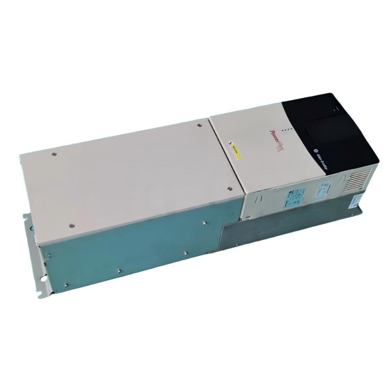
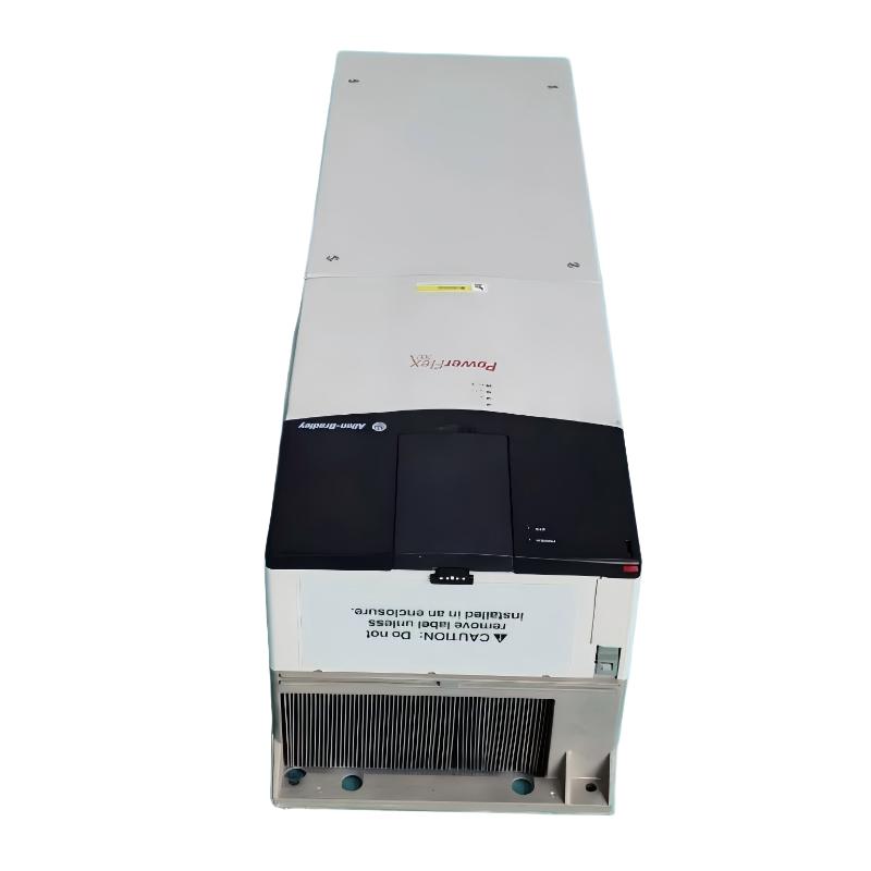
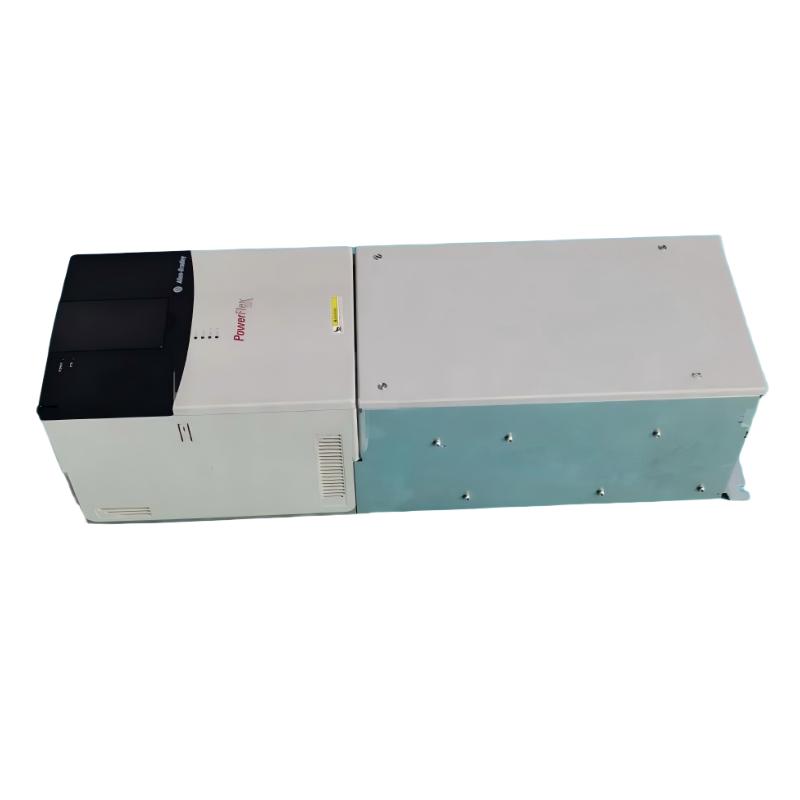
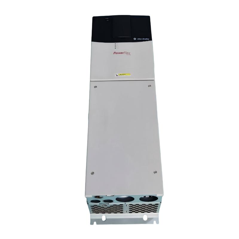
Allen-Bradley 20BD248A3ANNANC0 PowerFlex 700 AC Drive
1. Product Overview
The Allen-Bradley 20BD248A3ANNANC0 is an industrial variable-frequency AC drive associated with the PowerFlex 700 series. It is designed to regulate the speed of compatible AC motors and support industrial machinery that requires controlled acceleration, adjustable operating speed, and reliable motor operation.
The PowerFlex 700 family is intended for industrial applications in which motor speed and operating behavior must be matched to production requirements. Typical applications include pumps, fans, conveyors, mixers, material-handling systems, and selected types of process machinery.
The catalog number 20BD248A3ANNANC0 is associated with the 480 V-class PowerFlex 700 product range. The model designation suggests a high-current drive configuration, but the exact rated current, motor power, frame size, and installed options should be confirmed against the unit’s nameplate and technical documentation.
For industrial maintenance and purchasing, the most important considerations are the drive’s input supply, output-current capacity, overload rating, control interfaces, braking configuration, mounting dimensions, and physical condition. These factors determine whether a particular unit is suitable for an existing machine or a new installation.
2. Product Parameters and Technical Specifications
The table below provides a structured technical overview. Values that cannot be confidently established for this exact catalog number are identified as unconfirmed rather than presented as verified specifications.
|
Parameter
|
Specification
|
|
Brand
|
Allen-Bradley
|
|
Complete model number
|
20BD248A3ANNANC0
|
|
Product series
|
PowerFlex 700
|
|
Product category
|
Industrial AC drive
|
|
Drive type
|
Variable-frequency drive
|
|
Main function
|
Adjustable-speed AC motor control
|
|
Voltage class
|
480 V AC class
|
|
Input supply
|
Three-phase AC; verify the unit nameplate
|
|
Rated current
|
Exact rating not confirmed for this complete catalog number
|
|
Motor power rating
|
Not confirmed
|
|
Horsepower rating
|
Not confirmed
|
|
Kilowatt rating
|
Not confirmed
|
|
Output frequency range
|
Not confirmed
|
|
Motor-control modes
|
Confirm the installed configuration and available functions
|
|
Overload capacity
|
Not confirmed; depends on the applicable duty rating
|
|
Frame size
|
Not confirmed for this exact model
|
|
Enclosure / protection rating
|
Not confirmed for this exact suffix
|
|
Operator interface
|
Installed interface not confirmed
|
|
Communication options
|
Installed communication hardware not confirmed
|
|
Feedback interface
|
Not confirmed
|
|
Braking hardware
|
Exact configuration not confirmed
|
|
Cooling arrangement
|
Confirm the actual drive construction
|
|
Approximate dimensions (H × W × D)
|
Not confirmed for the exact model; approximately 850 × 403.9 × 275.5 mm has been associated with comparable high-current configurations
|
|
Approximate product weight
|
Not confirmed for the exact model; approximately 72.57 kg has been associated with a comparable configuration
|
|
Shipping weight
|
Not confirmed
|
|
Mounting arrangement
|
Confirm the mechanical drawing
|
|
Environmental requirements
|
Confirm the applicable installation instructions
|
|
Intended environment
|
Industrial motor-control installation, subject to the actual enclosure rating
|
|
Product lifecycle
|
Legacy drive family; availability depends on inventory and condition
|
|
Replacement compatibility
|
Requires electrical, mechanical, and control-system verification
|
Technical note: The dimensions and weight listed above are preliminary comparison values only. They are not confirmed specifications for the exact 20BD248A3ANNANC0. The complete catalog number and its suffix-specific options should be checked before ordering, installing, or replacing the drive.
3. Product Introduction
3.1 Industrial Motor-Speed Control
The main function of the 20BD248A3ANNANC0 is to regulate the operation of a compatible AC motor by adjusting the electrical output supplied to it.
In a fixed-speed motor installation, operating speed is primarily determined by the supply frequency, motor design, and mechanical load. A variable-frequency drive adds the ability to adjust speed to meet the needs of the process.
This capability is useful when equipment must operate at different speeds during startup, normal production, material transfer, or shutdown. The drive can be incorporated into a machine-control system in which operating commands come from an operator interface, control terminals, or a supported automation interface, depending on the installed configuration.
3.2 Controlled Acceleration and Deceleration
A drive can provide programmed acceleration and deceleration profiles within its operating limits.
This helps control how quickly a motor changes speed. For suitable machinery, gradual acceleration can reduce sudden torque changes and mechanical shock. Controlled deceleration can also help coordinate stopping with the process.
The actual stopping behavior depends on the motor, load inertia, configured ramp times, and available braking equipment. A drive’s ability to reduce its speed reference does not automatically mean that it can provide rapid braking or mechanically hold a load.
3.3 Integration Into Industrial Equipment
The PowerFlex 700 series is intended for industrial motor-control applications where drive operation may need to be coordinated with other equipment.
Depending on the specific hardware, the drive may operate as part of a system containing programmable controllers, sensors, operator controls, protection devices, and other motor-control equipment.
For existing installations, the original drive’s control wiring and configuration records are particularly important. A replacement with a different interface or option set may require changes to the control system and additional commissioning.
3.4 High-Current Drive Selection
The 20BD248A3ANNANC0 should be evaluated as a specific drive assembly rather than selected solely on the basis of its model designation.
A suitable drive must meet the motor’s electrical requirements and the load’s operating demands. Important factors include full-load current, starting torque, acceleration time, overload duration, and operating cycle.
For large or demanding loads, ambient temperature, installation altitude, cooling, and cabinet conditions can also influence the usable drive capacity.
4. Product Applications
4.1 Industrial Pump Systems
Pumps are widely used in water circulation, process-fluid transfer, industrial cooling, and liquid-handling systems.
A variable-frequency drive can adjust pump speed according to the required flow or pressure when the pump and process are suitable for variable-speed operation.
Potential benefits include improved process adjustment and reduced unnecessary full-speed operation. Actual energy savings depend on the pump type, system characteristics, operating hours, and control strategy.
Before selecting a drive for a pump, evaluate minimum speed, required flow, system pressure, motor cooling, and the operating limits of the pump and connected piping.
4.2 Fans and Blowers
Industrial fans and blowers are used in ventilation, cooling, exhaust, air circulation, and process-air systems.
A variable-frequency drive can regulate fan speed according to the required airflow. This may be useful where demand varies during production or where equipment does not need to run at full speed continuously.
The drive must be suitable for the fan motor’s current, load characteristics, inertia, and required speed range. Acceleration and deceleration settings should be selected according to the mechanical system and operating requirements.
4.3 Conveyor Systems
Conveyors are used in manufacturing, packaging, assembly lines, warehouses, and material-handling systems.
A drive can provide adjustable conveyor speed and controlled acceleration and deceleration. This can help coordinate product movement between stations and reduce abrupt changes in conveyor speed.
The application must be evaluated for starting torque, load variation, belt or chain characteristics, and stopping requirements. Conveyors that need rapid stopping or mechanical load holding may require additional braking or safety equipment.
4.4 Mixers and Agitators
Mixers and agitators may require different operating speeds for loading, blending, processing, and discharge.
A variable-frequency drive can support adjustable-speed operation where the mechanical equipment and process permit it. Controlled speed changes can help match the operating profile to different stages of production.
Selection should consider starting torque, load variation, continuous operating duration, low-speed motor cooling, and the required torque over the operating speed range.
4.5 Industrial Processing Equipment
Selected processing machines require controlled motor speed to coordinate material movement, process timing, or machine operation.
The PowerFlex 700 family may be considered for these applications when the drive’s verified electrical ratings and installed options meet the machine’s requirements.
The suitability of the 20BD248A3ANNANC0 cannot be established from its catalog number alone. Motor data, load characteristics, control interfaces, and the actual hardware configuration must all be evaluated.
4.6 Large Motor-Driven Machinery
High-current drive configurations may be relevant to larger industrial motor systems. However, the correct drive rating depends on the actual motor and application rather than motor size alone.
A suitable selection must account for continuous current, overload requirements, starting conditions, cooling, environmental derating, and the machine’s duty cycle.
5. Product Advantages
5.1 Flexible Speed Adjustment
Variable-speed operation allows a motor to run at the speed required by the process instead of relying exclusively on fixed-speed operation.
This flexibility can be useful when production rates change, equipment must coordinate with other machinery, or a process requires different operating speeds at different stages.
5.2 Controlled Motor Starting
A properly configured drive can increase motor speed gradually.
This can reduce abrupt changes in torque and help manage mechanical stress in suitable applications. The actual benefit depends on the machine, motor, load, and programmed acceleration profile.
5.3 Controlled Stopping
A drive can reduce motor speed according to configured deceleration settings.
This can help coordinate routine stops in pumps, fans, conveyors, and other machinery. If the application requires rapid deceleration or braking of an overhauling load, the drive’s braking capability must be assessed separately.
5.4 Potential Energy Savings
In suitable variable-torque applications, particularly centrifugal pumps and fans, reducing motor speed can lower energy consumption.
The amount of savings depends on the load, speed range, operating hours, mechanical system, and control strategy. Installing a drive does not guarantee savings in every application.
5.5 Industrial Automation Integration
The PowerFlex 700 family was developed for industrial motor-control environments.
Depending on the exact configuration, the drive may be integrated into an automation system using available control connections and supported communication options. This can help coordinate motor operation with other equipment.
For an existing machine, the installed communication and control interfaces must be identified before a replacement is selected.
5.6 Maintenance and Troubleshooting Support
Drive status and fault information can assist maintenance personnel in investigating abnormal operating conditions.
The available diagnostic information depends on the installed configuration. Effective troubleshooting should consider the drive, motor, load, power supply, wiring, and surrounding control system.
5.7 Potential Benefits for Existing Installations
When a machine already uses the PowerFlex 700 series, a compatible replacement from the same family may reduce the amount of modification required to the existing installation.
However, a similar model number does not guarantee that the hardware options are identical. The original and replacement units should be compared for electrical ratings, frame, control interface, communication options, and braking hardware.
5.8 Lifecycle Planning
The PowerFlex 700 is a legacy drive family, so spare-parts planning and replacement strategy are important for long-term machine maintenance.
Keeping records of the drive’s full catalog number, parameter settings, control wiring, motor data, and installed options can reduce troubleshooting time and simplify future replacement work.
6. Brand Information
|
Item
|
Description
|
|
Brand
|
Allen-Bradley
|
|
Product category
|
Industrial automation and motor control
|
|
Product type
|
Variable-frequency AC drive
|
|
Product family
|
PowerFlex
|
|
Specific series
|
PowerFlex 700
|
|
Model
|
20BD248A3ANNANC0
|
|
Primary function
|
AC motor speed regulation
|
|
Typical application environment
|
Industrial machinery and process systems
|
|
Main selection criteria
|
Voltage, current, duty rating, options, dimensions, and compatibility
|
Allen-Bradley is an established brand in industrial automation and motor-control equipment.
For this model, the most important considerations are the exact configuration, electrical ratings, installed options, and physical condition. The brand and series designation alone do not establish whether a specific unit is suitable for an installation.
7. Product Series: PowerFlex 700
The PowerFlex 700 series is designed for industrial AC motor-control applications that require adjustable speed and controlled operation.
The family contains different electrical ratings and catalog configurations. Individual drives may differ in their available interfaces, braking arrangements, enclosure construction, and other options.
Main Characteristics of the Series
– Industrial motor control: Supports adjustable-speed operation for compatible AC motors.
– Multiple electrical configurations: Different models accommodate different voltage and current requirements.
– Configurable operation: Actual control behavior depends on the drive hardware and programmed settings.
– Automation integration: Communication and control capabilities depend on the installed options.
– Legacy installation support: Existing systems may require careful configuration records and planned replacement arrangements.
Important Selection Factors
When selecting a PowerFlex 700 drive, check the complete catalog number, supply voltage, rated output current, motor full-load current, overload requirements, load inertia, braking needs, operator interface, communication options, enclosure rating, cooling requirements, and mechanical dimensions.
A replacement should be chosen on the basis of these verified requirements rather than on apparent similarity between catalog numbers.
8. Five Related Models in the Same Series or a Related Family
The following models are provided as preliminary comparison candidates from the PowerFlex 700 family or a related catalog-number range. They are not confirmed direct replacements for the 20BD248A3ANNANC0.
Where exact-model specifications cannot be confidently established, the table identifies the value as unconfirmed.
|
No.
|
Model
|
Series
|
General parameters
|
Dimensions (H × W × D)
|
Weight (kg)
|
|
1
|
20BD180A3ANNANC0
|
PowerFlex 700
|
480 V-class configuration; approximately 180 A associated with this related model; verify the exact nameplate
|
Approx. 850 × 403.9 × 275.5 mm for a comparable configuration; exact model unconfirmed
|
Approx. 71.44; exact variant unconfirmed
|
|
2
|
20BD180A3ANNAND0
|
PowerFlex 700
|
Related high-current configuration; exact electrical rating and suffix options require confirmation
|
Approx. 850 × 403.9 × 275.5 mm for a comparable configuration; exact model unconfirmed
|
Approx. 71.44; exact variant unconfirmed
|
|
3
|
20BD248A0ANNANA0
|
PowerFlex 700
|
Related 480 V-class configuration; approximately 248 A associated with this model designation; verify the actual ratings
|
Approx. 850 × 403.9 × 275.5 mm for a comparable configuration; exact model unconfirmed
|
Approx. 72.57; exact variant unconfirmed
|
|
4
|
20BD248A0ANNANC0
|
PowerFlex 700
|
Related model in the approximately 248 A range; exact hardware options require confirmation
|
Approx. 850 × 403.9 × 275.5 mm for a comparable configuration; exact model unconfirmed
|
Approx. 72.57; exact variant unconfirmed
|
|
5
|
20BD248A3ANNANC0
|
PowerFlex 700
|
Reference model; verify exact current, power rating, frame, enclosure, and installed options
|
Not confirmed for the exact model
|
Not confirmed
|
Related-Model Selection Notes
The 180 A and 248 A configurations should not be regarded as interchangeable. A lower-current drive may be unable to meet the motor’s continuous current or overload requirements.
The full catalog number is also important because suffix differences can indicate differences in hardware or options. Do not assume that similar models have identical braking capability, communication interfaces, feedback support, or operator interfaces.
The approximate dimensions and weights in the table are comparison estimates only. Confirm the exact mechanical specifications before planning cabinet installation, lifting, or shipping.
9. Five Other Allen-Bradley Models for Broader Comparison
The following models belong to other PowerFlex drive families and may be useful when comparing industrial motor-control products. They cover different application and capacity categories and should not be treated as direct substitutes for the reference model.
|
No.
|
Model
|
Series
|
General parameters
|
Dimensions (H × W × D)
|
Weight (kg)
|
|
1
|
25B-D024N104
|
PowerFlex 525
|
Compact AC drive family; exact voltage, current, and motor capacity require confirmation
|
Not confirmed
|
Not confirmed
|
|
2
|
25B-D017N104
|
PowerFlex 525
|
Compact variable-frequency drive for selected industrial applications; verify the exact electrical rating
|
Not confirmed
|
Not confirmed
|
|
3
|
25B-D010N104
|
PowerFlex 525
|
Compact AC motor-control drive; confirm voltage, output current, and options
|
Not confirmed
|
Not confirmed
|
|
4
|
22B-D012N104
|
PowerFlex 40
|
Compact general-purpose AC drive; verify electrical ratings and motor compatibility
|
Not confirmed
|
Not confirmed
|
|
5
|
22B-D017N104
|
PowerFlex 40
|
General-purpose compact drive family; exact rating and installed options require confirmation
|
Not confirmed
|
Not confirmed
|
PowerFlex 525
The PowerFlex 525 family is associated with compact AC drives for a variety of machine-level applications. It may be considered when designing new equipment or evaluating a different drive architecture.
A PowerFlex 525 should not be assumed to replace a high-current PowerFlex 700 without a complete engineering assessment. Current capacity, enclosure, braking, mounting, and control-system requirements may differ substantially.
PowerFlex 40
The PowerFlex 40 is a compact drive family intended for general-purpose AC motor control. Its suitability depends on the actual drive rating and application.
Because it is a different product family, its mounting arrangement, electrical capacity, interfaces, and operating characteristics should be compared carefully before considering it for an existing installation.
Choosing Between Series
When selecting an alternative, start with the motor’s electrical requirements and the machine’s operating profile. A different drive family may require changes to the cabinet, wiring, communication architecture, parameter settings, or commissioning procedure.
For a legacy machine, maintaining compatibility with the original installation may be more practical than selecting a product based only on general functionality.
10. Dimensions, Weight, and Installation Requirements
The physical dimensions and weight of a drive affect cabinet layout, mounting, cable routing, transport, and lifting arrangements.
For a comparable high-current PowerFlex 700 configuration, preliminary reference figures are approximately 850 mm in height, 403.9 mm in width, 275.5 mm in depth, and 72.57 kg in product weight. These figures are not confirmed for the exact 20BD248A3ANNANC0.
|
Mechanical parameter
|
Value
|
|
Height
|
Not confirmed for the exact model; comparable configurations are approximately 850 mm
|
|
Width
|
Not confirmed for the exact model; comparable configurations are approximately 403.9 mm
|
|
Depth
|
Not confirmed for the exact model; comparable configurations are approximately 275.5 mm
|
|
Product weight
|
Not confirmed for the exact model; comparable configurations are approximately 72.57 kg
|
|
Shipping weight
|
Not confirmed
|
|
Mounting-hole pattern
|
Not confirmed
|
|
Required clearance
|
Confirm the applicable installation instructions
|
|
Cable-entry requirements
|
Confirm the physical configuration
|
|
Cabinet ventilation requirements
|
Confirm the applicable installation instructions
|
Before installation, verify the actual drive dimensions, mounting-hole positions, wiring space, cooling-air clearances, cabinet temperature, and support structure.
The weight of the complete installation may also differ from the drive’s own weight if additional braking, filtering, or other equipment is fitted separately.
For the other recommended models, exact dimensions and weights remain unconfirmed. These should be obtained from the corresponding mechanical drawings or checked against the actual units before installation or transport.
11. Purchasing and Replacement Recommendations
11.1 Verify the Complete Catalog Number
Confirm that the catalog number on the unit matches the intended product. Record the nameplate details and any additional option labels.
11.2 Confirm Electrical Compatibility
Compare the incoming supply voltage, phase, frequency, motor full-load current, and drive output-current capacity. Do not select a drive solely on the basis of a presumed horsepower rating.
11.3 Evaluate the Duty Requirements
Determine whether the application requires normal-duty or heavy-duty operation. High starting torque, frequent starts, long acceleration times, and sustained overload can affect drive selection.
11.4 Check the Installed Options
Identify the operator interface, communication hardware, feedback interface, and braking arrangement. Similar catalog numbers may have different options.
11.5 Verify the Mechanical Fit
Check height, width, depth, mounting points, cable-bending space, cooling clearances, and weight. These factors are especially important when replacing a drive inside an existing cabinet.
11.6 Inspect Used or Refurbished Equipment
For a used unit, review its operating history, storage conditions, physical condition, cooling components, terminals, and test records where available.
A matching catalog number does not guarantee that the drive is functional or ready for installation.
11.7 Plan Commissioning Carefully
Before energizing the drive, check grounding, protective devices, motor connections, control wiring, parameter settings, and the machine’s safety requirements. Commissioning should be performed by qualified personnel following the applicable installation instructions.
12. Final Summary
The Allen-Bradley 20BD248A3ANNANC0 is associated with the PowerFlex 700 family of industrial AC drives and the 480 V-class product range. Its intended purpose is to provide adjustable-speed control for compatible industrial motors.
Potential applications include pumps, fans, conveyors, mixers, processing equipment, and other motor-driven machinery. Its potential advantages include adjustable speed, controlled acceleration and deceleration, process flexibility, and integration into suitable industrial motor-control systems.
For purchasing and replacement decisions, the most important considerations are the exact electrical ratings, motor-current requirements, overload capacity, installed hardware, control-system compatibility, dimensions, weight, and actual condition.
The recommended models above are preliminary comparison candidates rather than confirmed interchangeable products. Exact-model dimensions, weights, and suffix-specific specifications remain unconfirmed where stated. The unit’s nameplate and mechanical documentation should be checked before ordering or installation.