

ProductPRODUCT
Featured products
Contact Us
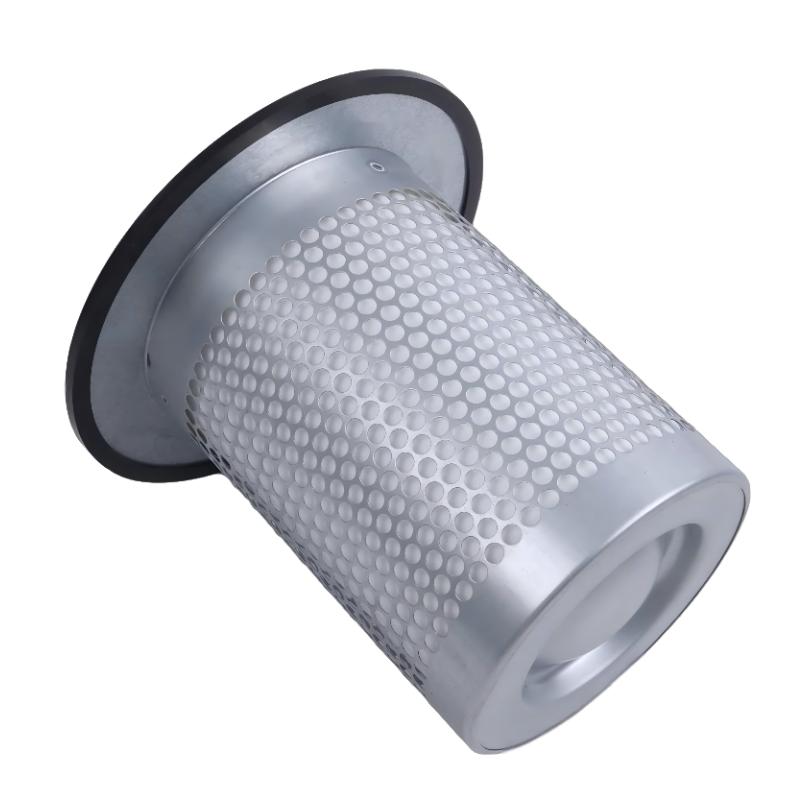
- Ingersoll Rand
- 47629377001 23675010
- Air-Oil Separator
- USA
- 340 × 65 × 200 mm
- 0.9 kg
- Xiamen, China
- New & In Stock
- T/T, PayPal, Western Union
- 1 Year
- 1-3 Working Days
- DHL, UPS, TNT, FedEx and EMS.
- 24-Hour Service
- COO
- 3
Our advantage

Global Logistics
We have a 10-year logistics and express cooperation agreement, so our products can be shipped to any place in the world.

Brand new and original
Our products are imported in bulk from the place of origin. Because of the cooperative relationship, our products are all original and 100% new.

24-hour service
We provide 7*24 hours service to our customers. We will be there whenever you need us.

Price advantage
All our products are priced very favorably because we have our own warehouse and supply.
| Company Information | |||
| [email protected] | |||
| Mobile | +8615980777398 | ||
| +8615980777398 | |||
| 15980777398 |
1. Product Overview
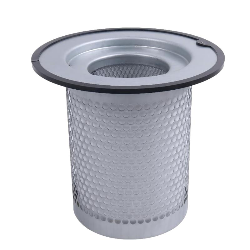
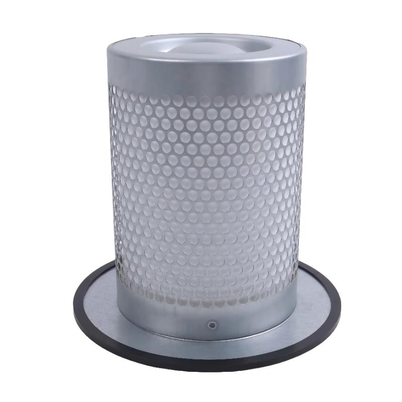
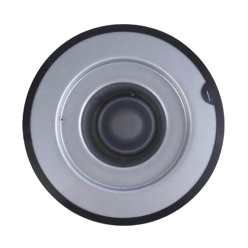
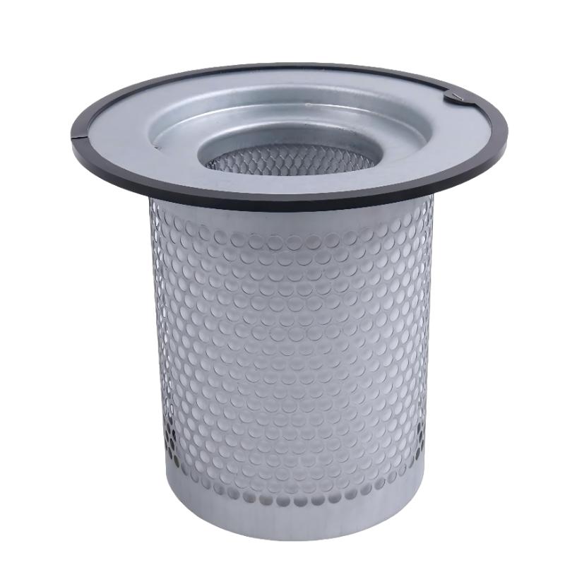
The Ingersoll Rand 47629377001 / 23675010 Air-Oil Separator is an industrial compressor replacement component associated with air and oil separation in compressed air systems. Air-oil separation is an important part of oil-injected compressor operation because it helps reduce the amount of lubricating oil carried into the compressed air stream while supporting the recovery and circulation of oil within the compressor system.
During compression, lubricating oil may become mixed with compressed air. The separator helps separate oil droplets from the air before the compressed air moves downstream. Effective separation supports compressed air quality, reduces oil carryover, and helps maintain stable compressor operation.
The Ingersoll Rand 47629377001 and 23675010 part numbers are associated with the product information supplied for this listing. Before ordering, maintenance teams should confirm whether both numbers identify the same component, a superseded part, or separate configurations. Part-number relationships should be verified against the compressor model, equipment serial number, and existing component label.
With listed dimensions of 340 × 65 × 200 mm and a weight of 0.9 kg, this component can be evaluated for maintenance planning, replacement-part inventory, and equipment servicing. Dimensions and weight alone, however, are not sufficient to establish compatibility with a particular compressor.
2. Technical Specifications
| Specification | Details |
|---|---|
| Brand | Ingersoll Rand |
| Part Number | 47629377001 |
| Associated Part Number | 23675010 |
| Product Name | Air-Oil Separator |
| Product Type | Compressor air-oil separation component |
| Dimensions | 340 × 65 × 200 mm |
| Weight | 0.9 kg |
| Primary Function | Helps separate lubricating oil from compressed air |
| Typical Equipment | Compatible oil-injected compressor systems |
| Installation Location | Determined by the compressor design |
| Filter or Separation Media | Verify for the exact part number |
| Separation Efficiency | Verify from the applicable technical specification |
| Operating Pressure | Verify against the compressor requirements |
| Operating Temperature | Verify against the compressor requirements |
| Compatible Compressor Models | Confirm using the equipment model and serial number |
| Replacement Status | Confirm part-number equivalence before ordering |
The table contains the supplied product identifiers and physical specifications. Performance values and equipment compatibility should be checked against the exact component specification rather than estimated from its appearance or dimensions.
3. Function and Working Principle
3.1 Separation of Oil from Compressed Air
In an oil-injected compressor, lubricating oil can perform several functions, including lubrication, cooling, and sealing. As air and oil move through the compression process, some oil remains suspended in the compressed air as droplets or mist.
The air-oil separator is designed to reduce this oil carryover. Depending on the separator design, the separation process may use coalescing media or other separation structures that encourage oil droplets to collect and drain away from the compressed air stream.
The exact internal construction of the Ingersoll Rand 47629377001 / 23675010 should be confirmed from its product documentation. The general separation principle does not establish the specific media type, filtration rating, or efficiency of this individual component.
3.2 Supporting Oil Recovery
Separated oil may be returned to the compressor lubrication circuit through the equipment’s designated oil-return arrangement. This helps maintain the intended oil circulation process and reduces unnecessary oil loss.
The oil-return arrangement varies by compressor design. During maintenance, technicians should inspect the relevant hoses, fittings, return passages, and associated components for restrictions, damage, or incorrect assembly.
3.3 Helping Control Oil Carryover
Excessive oil carryover can affect downstream equipment, compressed air applications, and operating costs. A properly selected and maintained separator helps control this issue.
A separator cannot compensate for every possible cause of oil carryover. Incorrect oil level, unsuitable lubricant, abnormal operating conditions, damaged seals, or a malfunctioning oil-return system may also contribute to the problem.
3.4 Maintaining Compressor Performance
As a separator becomes contaminated or reaches the end of its service life, airflow resistance may increase. Depending on the compressor design and operating conditions, this can contribute to increased pressure differential, reduced operating efficiency, or maintenance alarms.
The replacement interval should follow the applicable compressor maintenance requirements and operating conditions. A universal service interval should not be assumed for every installation.
4. Role in Industrial Compressor Systems
4.1 Compressed Air Quality
Air-oil separation helps limit the amount of lubricant that passes into the compressed air network. This is important in applications where oil contamination can affect pneumatic equipment, production processes, or downstream treatment devices.
The separator alone does not guarantee oil-free compressed air. Where a process requires a specified oil-content level, the complete compressor and air-treatment system must be evaluated against that requirement.
4.2 Protection of Downstream Equipment
Excessive oil carryover can contribute to contamination of air receivers, pipework, valves, pneumatic cylinders, and downstream filters. Effective separation helps reduce this risk when the component is correctly selected and the rest of the system is operating properly.
Additional filtration or treatment may still be required according to the application’s air-quality requirements.
4.3 Compressor Reliability
A separator operating outside its intended condition may affect compressor performance. Monitoring oil carryover, pressure differential where supported, operating temperature, and maintenance history can help identify developing problems.
Maintenance personnel should use the compressor’s approved monitoring points and service procedures rather than applying diagnostic thresholds that have not been specified for the equipment.
4.4 Maintenance and Inventory Management
Keeping the correct separator available can help reduce downtime during scheduled servicing or unexpected maintenance. Inventory records should include the full part number, associated equipment model, serial-number applicability, and any confirmed supersession information.
Where 47629377001 and 23675010 appear in purchasing or maintenance records, their relationship should be documented after verification. Similar dimensions or shared product descriptions do not independently prove that two part numbers are interchangeable.
5. Industrial Applications
5.1 Manufacturing Facilities
Manufacturing plants use compressed air for pneumatic actuators, automated assembly equipment, material handling, and general production services. The air-oil separator supports the compressor’s separation process and helps control oil carryover into the compressed air network.
5.2 Industrial Automation Systems
Compressed air is commonly used in automated production lines for valve actuation, clamping, positioning, and other pneumatic operations. Proper compressor maintenance helps reduce contamination-related problems and supports consistent equipment operation.
The separator is part of the compressed air supply system; it is not a PLC, control module, or electronic automation component.
5.3 Workshops and Maintenance Facilities
Industrial workshops may depend on compressed air for pneumatic tools, cleaning equipment, and general maintenance tasks. Selecting the correct replacement separator helps maintain the compressor according to its specified operating requirements.
5.4 Packaging and Processing Equipment
Packaging machinery and processing systems may use compressed air for movement, product handling, and control functions. The required air quality depends on the process and any applicable hygiene or contamination-control requirements.
Applications with strict air-purity requirements may need additional downstream treatment beyond the compressor’s internal separator.
5.5 Continuous-Duty Compressor Installations
Facilities operating compressors for extended periods should monitor maintenance history and signs of declining separation performance. The correct separator, installed according to the compressor manufacturer’s procedures, helps maintain the intended air-oil separation process.
6. Installation and System Integration
Correct installation is important for separator performance, compressor reliability, and personnel safety. The precise installation procedure depends on the compatible compressor model and separator configuration.
Step 1: Confirm the Part Number
Before beginning work, check the existing component label, compressor model, equipment serial number, and parts documentation. Confirm whether Ingersoll Rand 47629377001 or 23675010 is the required replacement identifier.
Do not rely only on dimensions, weight, or a general product description when determining compatibility.
Step 2: Shut Down and Isolate the Compressor
Stop the compressor using the approved shutdown procedure. Isolate the electrical supply and follow the site’s lockout/tagout requirements.
Allow the system to cool and fully relieve stored pressure according to the compressor’s service instructions. Never loosen a pressurized separator housing or connection.
Step 3: Inspect the Existing Assembly
Before removing the existing component, inspect the surrounding housing, sealing surfaces, fittings, and accessible oil-return components. Record any unusual oil accumulation, leakage, contamination, or signs of damage.
If the original separator failed prematurely, investigate the underlying cause rather than replacing the component without further inspection.
Step 4: Remove the Existing Separator
Follow the disassembly procedure specified for the relevant compressor. Use suitable tools and avoid damaging the housing, threads, sealing surfaces, or nearby pipework.
Dispose of the used separator and any collected oil in accordance with site environmental and waste-handling requirements.
Step 5: Check the Replacement Component
Compare the replacement with the removed component and verify the part number, physical configuration, sealing arrangement, and specified installation orientation.
The supplied dimensions of 340 × 65 × 200 mm can support a preliminary physical comparison, but they do not establish correct internal performance or compatibility.
Do not modify the component to force a fit. If any connection, seal, or mounting feature differs, stop and verify the correct part.
Step 6: Install According to the Equipment Procedure
Install the replacement using the specified seals, fittings, orientation, and tightening requirements. Use only approved replacement materials and lubricants where the service instructions call for them.
Do not guess torque values, seal types, or installation direction. These details must be taken from the documentation for the exact compressor and separator assembly.
Step 7: Inspect the Oil-Return System
Where the compressor design uses a dedicated oil-return line or passage, check it for blockage, damage, or incorrect routing. A restricted return path may affect separation performance even when the separator itself is new.
Only carry out checks that are applicable to the specific compressor design.
Step 8: Restart and Check Operation
Restore the system according to the approved commissioning procedure. Check for leaks, abnormal noise, unexpected alarms, and other signs of incorrect installation.
Where the equipment provides a separator pressure-differential measurement or other relevant operating indication, compare the readings with the compressor’s specified limits.
Step 9: Record the Maintenance Work
Document the installed part number, date of replacement, equipment identification, operating observations, and any additional corrective work. This record supports future maintenance planning and helps identify recurring separator problems.
7. Compatible System Components
An air-oil separator operates as part of a larger compressor assembly. The following components may be relevant during inspection or maintenance, depending on the compressor configuration.
| Component | Relationship to the Separator | Maintenance Consideration |
|---|---|---|
| Compressor Assembly | Provides the operating environment for air-oil separation | Confirm exact model and serial-number compatibility |
| Lubricating Oil | Supports lubrication, cooling, and sealing in applicable compressors | Use the specified oil grade and service procedure |
| Oil-Return Line or Passage | Returns separated oil where the design includes this arrangement | Check for restrictions and incorrect routing |
| Separator Housing | Supports and seals the separator assembly where applicable | Inspect sealing surfaces and mounting features |
| Pressure and Temperature Sensors | Provide operating information on equipped systems | Check readings against approved limits |
| Downstream Air Filter | Provides additional treatment when installed | Confirm the required filtration level |
| Air Receiver and Pipework | Receive and distribute compressed air | Inspect for oil accumulation or contamination when relevant |
| Compressor Control System | Monitors and controls compressor operation | Review alarms and operating history during diagnosis |
This table identifies functional relationships, not a verified list of parts supplied with or guaranteed to be compatible with the 47629377001 / 23675010 separator.
8. Recommended Alternative Models and Replacement Selection
Selecting an alternative separator requires confirmation of the compressor model, equipment serial number, original part number, physical configuration, operating requirements, and documented replacement status.
| Replacement Option | Recommendation | Verification Required |
|---|---|---|
| Ingersoll Rand 47629377001 | Candidate when this is the specified part number | Confirm equipment applicability and current part status |
| Ingersoll Rand 23675010 | Candidate associated with the supplied product listing | Confirm whether it is equivalent to, or a replacement for, 47629377001 |
| Manufacturer-Approved Successor | Consider when an official supersession is documented | Confirm the successor part number and applicability |
| Third-Party Compatible Separator | Consider only after technical evaluation | Verify dimensions, sealing, separation performance, pressure and temperature ratings, and operating suitability |
No other specific model is presented as a confirmed direct substitute because equivalent performance and interchangeability have not been established from the supplied information.
For purchasing and maintenance purposes, the safest selection method is to match the component against the compressor’s parts documentation and verify any part-number changes before installation.
9. Key Advantages of Correct Separator Selection
Supports Oil Carryover Control
A suitable separator helps the compressor reduce the amount of lubricating oil carried into the compressed air stream under its intended operating conditions.
Helps Maintain Compressor Efficiency
Using the correct component and replacing it according to the applicable maintenance requirements can help prevent problems associated with an excessively restricted or unsuitable separator.
Supports Downstream Equipment Protection
Controlling oil carryover helps reduce the risk of oil contamination in downstream air equipment, although additional treatment may still be necessary.
Improves Maintenance Planning
Accurate part-number records and equipment-specific replacement procedures help maintenance teams prepare spare parts and reduce delays during servicing.
Supports Reliable Equipment Operation
Correct installation, suitable lubricant, a functioning oil-return system, and regular operating checks all contribute to the intended performance of the compressor system.
10. Technical FAQs
Q1: What is the function of the Ingersoll Rand 47629377001 Air-Oil Separator?
Its stated product function is air-oil separation in a compatible compressor system. The separator helps reduce lubricating oil carryover into compressed air. The exact performance characteristics depend on the specific component design and operating conditions.
Q2: Is 23675010 interchangeable with 47629377001?
The supplied listing associates both numbers with this product, but that information alone does not prove that the numbers are direct equivalents. Confirm the relationship through the applicable compressor parts documentation or an authorized parts specialist before ordering.
Q3: What are the dimensions and weight of this separator?
The supplied specifications list dimensions of 340 × 65 × 200 mm and a weight of 0.9 kg. Verify these details against the physical component and purchasing specification before using them for a final fit assessment.
Q4: Which Ingersoll Rand compressor models use this separator?
The compatible compressor models have not been established from the supplied product information. Check the compressor model and serial number against the applicable parts documentation before purchasing.
Q5: What are the signs of an air-oil separator problem?
Possible symptoms in a compressor system include increased oil carryover, abnormal separator pressure differential where monitored, oil consumption changes, or maintenance alarms. These symptoms can also result from other problems, so diagnosis should consider oil level, lubricant condition, return passages, seals, and overall operating conditions.
Q6: Can a new separator solve excessive oil carryover?
Not always. Excessive carryover may result from an incorrect separator, unsuitable lubricant, incorrect oil level, a restricted oil-return path, damaged seals, or abnormal operating conditions. Investigate the underlying cause before assuming the separator is the only problem.
Q7: How often should the separator be replaced?
Use the maintenance schedule specified for the compatible compressor and adjust servicing according to the approved guidance for actual operating conditions. A universal replacement interval cannot be confirmed for this part from the supplied information alone.
Q8: Can a separator with similar dimensions be used as a substitute?
Not without further verification. Similar dimensions do not establish equivalent separation efficiency, pressure rating, temperature rating, sealing configuration, or compatibility with the compressor.
Q9: Does this component make the compressed air completely oil-free?
The separator helps reduce oil carryover, but it should not be treated as a guarantee of completely oil-free compressed air. Applications with strict air-quality requirements may need additional filtration or treatment and verification of the complete system’s performance.
Q10: What information should be provided when requesting a replacement?
Provide the complete part number, compressor model, equipment serial number, existing component identification, and any documented supersession information. Photographs and physical measurements may help with preliminary identification but should not replace a compatibility check.
11. Conclusion
The Ingersoll Rand 47629377001 / 23675010 Air-Oil Separator is identified as an industrial compressor air-oil separation component, with supplied dimensions of 340 × 65 × 200 mm and a weight of 0.9 kg. Its intended role is to help reduce lubricating oil carryover and support the normal operation of a compatible compressor system.
For reliable replacement, maintenance teams should verify the exact part-number relationship, compressor compatibility, installation requirements, and operating specifications before ordering or fitting the component. Proper installation, inspection of the oil-return arrangement where applicable, and monitoring of compressor operating conditions can help support dependable performance and effective maintenance planning.