

ProductPRODUCT
Featured products



Contact Us
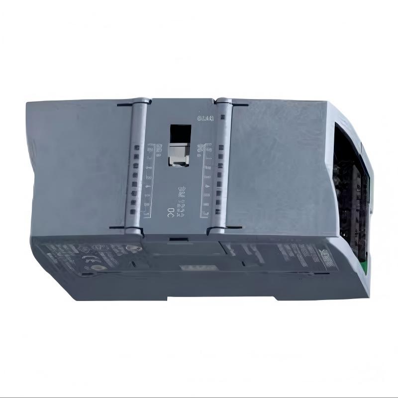
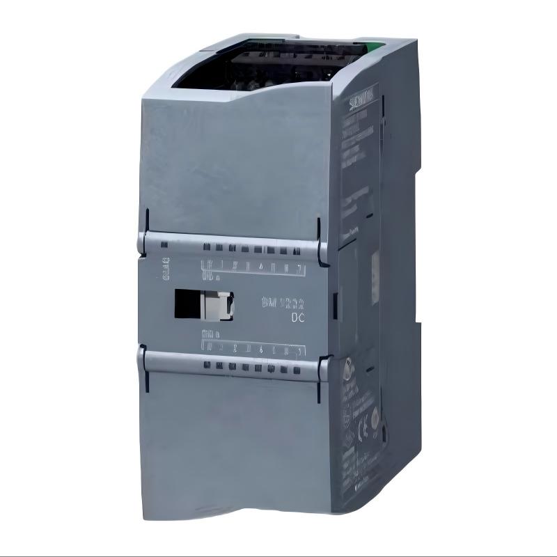
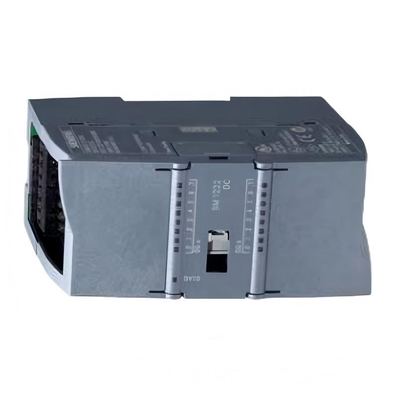
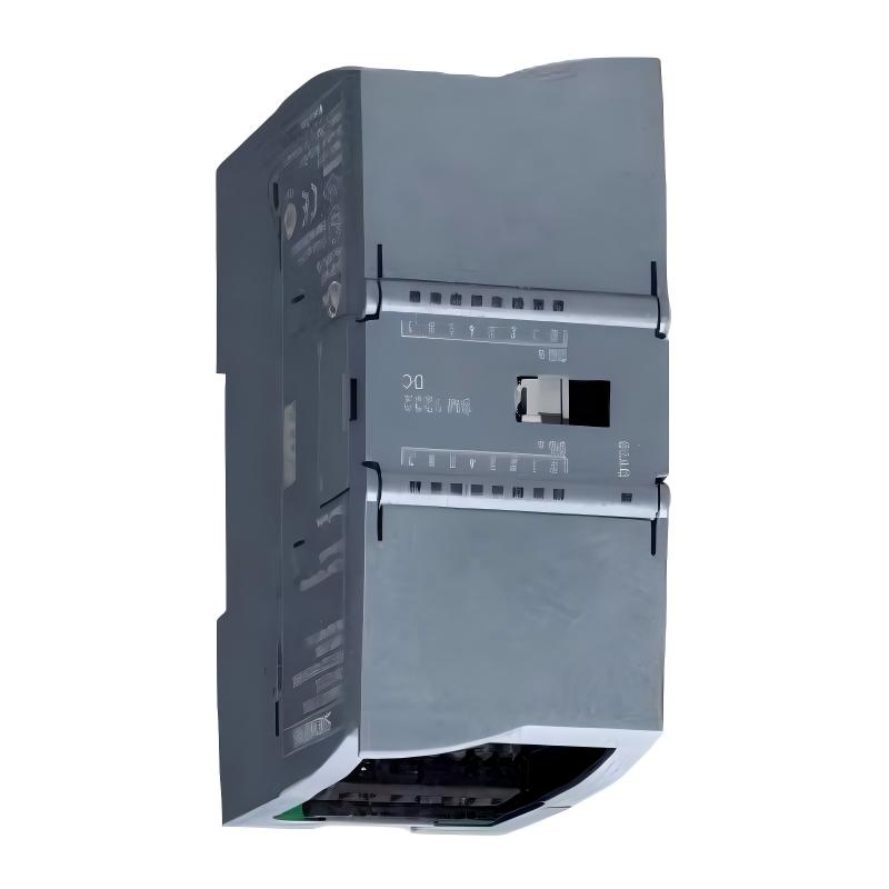
- Siemens
- 6AG1222-1BF32-4XB0
- Digital Output Module
- Germany
- 45 × 100 × 75 mm
- 0.162 kg
- Xiamen, China
- New & In Stock
- T/T, PayPal, Western Union
- 1 Year
- 1-3 Working Days
- DHL, UPS, TNT, FedEx and EMS.
- 24-Hour Service
- COO
- 2
Our advantage

Global Logistics
We have a 10-year logistics and express cooperation agreement, so our products can be shipped to any place in the world.

Brand new and original
Our products are imported in bulk from the place of origin. Because of the cooperative relationship, our products are all original and 100% new.

24-hour service
We provide 7*24 hours service to our customers. We will be there whenever you need us.

Price advantage
All our products are priced very favorably because we have our own warehouse and supply.
| Company Information | |||
| [email protected] | |||
| Mobile | +8615980777398 | ||
| +8615980777398 | |||
| 15980777398 |
1. Product Overview
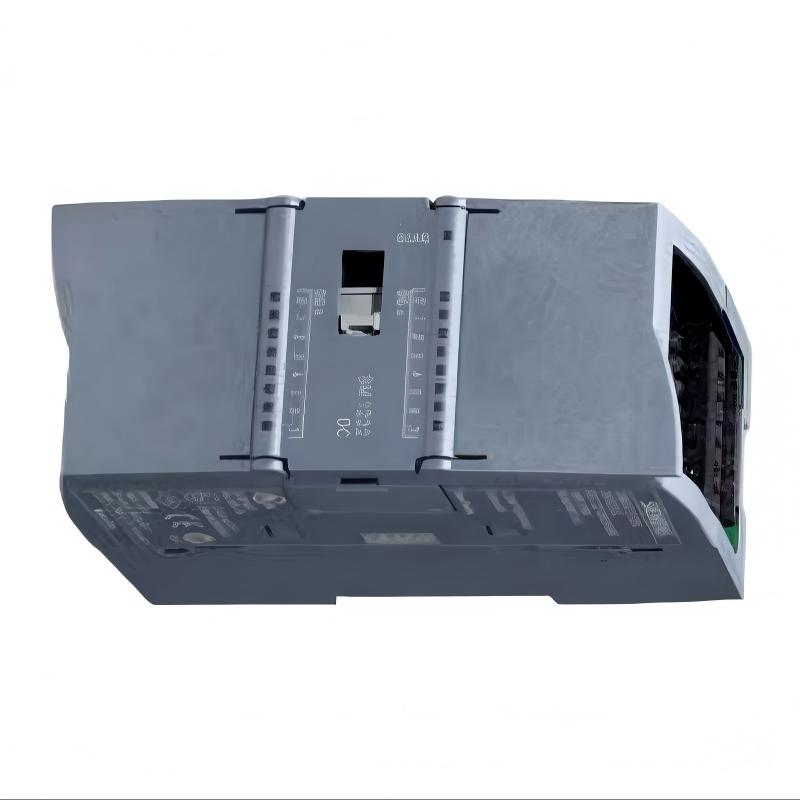
The Siemens 6AG1222-1BF32-4XB0 Digital Output Module is an industrial automation component designed for digital signal output within compatible Siemens SIMATIC control systems. Digital output modules provide the interface between a programmable logic controller (PLC) and field devices, allowing the controller to execute programmed commands and coordinate machine operations, process sequences, and equipment status signals.
In an industrial control environment, digital outputs are commonly used to control devices that operate through discrete ON/OFF signals. Depending on the module configuration and the connected electrical circuits, these devices may include indicator lamps, interface relays, contactors, solenoid valves, and other binary control elements. Correct module selection and integration help ensure that PLC commands are transferred to the field level in a predictable and maintainable manner.
The 6AG1222-1BF32-4XB0 model belongs to the Siemens product identification family associated with digital output modules. Before installation, engineers should confirm the exact electrical characteristics, channel configuration, output technology, and system compatibility using the product label and the documentation for the specific ordering number. Specifications from a similar module should not be assumed to apply automatically to this exact model.
For industrial facilities maintaining Siemens automation equipment, selecting the correct output module is important for reliable machine control, spare-parts planning, and lifecycle maintenance. The compact physical dimensions of this unit can also be useful when evaluating replacement components for existing control cabinets, subject to confirmation of mounting, wiring, and system requirements.
2. Technical Specifications
| Parameter | Specification |
|---|---|
| Brand | Siemens |
| Model Number | 6AG1222-1BF32-4XB0 |
| Product Type | Digital Output Module |
| Product Family | Siemens SIMATIC automation product family; confirm exact family and configuration |
| Dimensions | 45 × 100 × 75 mm |
| Weight | 0.162 kg |
| Main Function | Digital signal output for industrial control |
| Application | PLC-controlled machines and industrial automation systems |
| Output Technology | Verify against the exact model documentation |
| Number of Output Channels | Verify against the exact model documentation |
| Rated Output Voltage | Verify against the exact model documentation |
| Maximum Output Current | Verify against the exact model documentation |
| Output Protection | Verify against the exact model documentation |
| Electrical Connection | Confirm the connector and wiring arrangement for this exact model |
| Mounting Method | Confirm according to the associated hardware configuration |
| System Compatibility | Verify CPU, firmware, hardware configuration, and installation requirements |
The listed dimensions are 45 × 100 × 75 mm, and the stated weight is 0.162 kg. These values should be considered during control cabinet layout, spare-parts management, and equipment replacement planning.
Electrical characteristics are especially important when selecting a digital output module. The rated voltage, permitted load current, output circuit design, channel grouping, and protective functions determine whether the module can operate the intended field devices safely. These parameters must be confirmed before the module is connected to an energized control system.
3. Function and Working Principle
3.1 Converting PLC Commands into Digital Signals
A digital output module receives output commands from the PLC’s control program and uses its output circuits to control connected field devices. The PLC program evaluates input signals, internal logic, operating conditions, timers, counters, and interlocks before determining which outputs should be activated.
For example, a PLC-controlled packaging machine may need to activate an indicator lamp when a production cycle begins. The program evaluates the machine’s operating state and issues the corresponding output command. The digital output module then changes the relevant output state, allowing the connected circuit to operate the indicator.
The actual electrical behavior depends on the module’s output technology and circuit design. Engineers must confirm these details before determining how the output should be wired or what type of load it can control.
3.2 Discrete Output Control
Digital outputs are designed for discrete states rather than continuously variable analog values. Typical control applications include:
- Starting or stopping compatible control circuits.
- Activating status indicators.
- Operating interface relays.
- Sending discrete commands to auxiliary equipment.
- Controlling solenoid valves through appropriately rated circuits.
- Signaling the operating state of a machine to other control equipment.
The module’s specific channel count and electrical ratings determine how many devices can be controlled and which loads are suitable. A digital output should not be assumed to support a particular load merely because the load uses an ON/OFF signal.
3.3 Coordination with the PLC Program
The output module operates as part of a larger control architecture. The PLC program determines the requested output state, while the module provides the hardware interface needed to drive the external circuit.
A typical control sequence may involve the following steps:
- The PLC receives signals from sensors, switches, or other input devices.
- The control program evaluates the machine conditions and programmed interlocks.
- The PLC updates the requested output states.
- The digital output module changes the corresponding output circuits when operating conditions permit.
- Connected field devices respond to the resulting electrical signals.
- Feedback signals, where provided, allow the PLC to monitor the process or detect abnormal conditions.
The output module alone does not guarantee that a field device has physically operated. For applications requiring confirmation, engineers should use appropriate feedback devices and program diagnostic logic.
3.4 Protection and Electrical Load Considerations
Industrial output circuits may be exposed to overloads, wiring faults, inductive switching transients, or other electrical disturbances. The protective functions available depend on the exact module design.
Before connecting a load, engineers should verify:
- The rated voltage and current limits.
- Whether the output is designed for the intended load type.
- The permitted current per channel and for grouped channels.
- Any requirements for external protective devices.
- The handling of inductive loads, including relays and solenoid valves.
- The required common connections and power supply arrangement.
Loads that exceed the module’s electrical ratings may cause malfunction, overheating, or permanent damage. Where a field device draws more current than the output can safely provide, a correctly rated interface relay or contactor may be required.
4. Role in Industrial Control Systems
4.1 Machine Automation
In machine automation, digital output modules execute commands generated by the PLC. They can support discrete control functions such as status indication, auxiliary equipment operation, and the activation of properly rated control circuits.
For equipment manufacturers, a correctly configured output module helps maintain predictable sequence control and simplifies integration between the controller and field devices.
4.2 Process Control
Industrial process systems often combine analog measurements with discrete control actions. Temperature, pressure, flow, or level measurements may be processed by the controller, which then activates or deactivates associated equipment according to programmed conditions.
A digital output module can participate in these control sequences by issuing discrete commands to suitable field circuits. The precise role depends on the process design, connected devices, and safety requirements.
4.3 Equipment Status and Alarm Signaling
Digital outputs may be used to drive local indicators or send discrete status signals to external equipment. Examples include running indicators, fault lamps, and requests for auxiliary equipment operation.
Alarm handling should be designed carefully. A standard digital output should not be treated as a safety-rated output unless the exact hardware and system design explicitly support the required safety function.
4.4 Control Cabinet Maintenance
For maintenance teams, correct identification of the 6AG1222-1BF32-4XB0 is important when checking cabinet inventory, planning replacements, and documenting installed hardware.
Before replacing an existing module, engineers should compare the full ordering number, terminal arrangement, output characteristics, mounting requirements, and controller configuration. A module that looks similar or shares part of a model number may not be electrically or functionally interchangeable.
5. Industrial Applications
5.1 Manufacturing and Assembly Lines
Manufacturing lines use discrete outputs to coordinate machine sequences, operate indicators, and issue commands to auxiliary devices. The module may be considered for these applications when its electrical characteristics match the connected field circuits and the PLC system supports the hardware.
5.2 Packaging Machinery
Packaging equipment often relies on PLC-based sequence control for conveyors, product positioning, cycle indicators, and auxiliary mechanisms. Digital outputs can activate suitable interface circuits in response to programmed machine states.
For applications involving motors or high-current loads, the output module should normally command appropriately rated switching equipment rather than directly supply a load beyond its specified capacity.
5.3 Material Handling Systems
Conveyors, transfer stations, and automated handling equipment use discrete commands to coordinate operating states and peripheral devices. Output modules can support these functions when properly integrated with the PLC program, power distribution, and field wiring.
5.4 Industrial Utilities
Utility systems may use digital outputs to control auxiliary equipment, indicate operating conditions, or initiate discrete control actions. Engineers should verify that the module’s electrical specifications and environmental ratings are appropriate for the installation location.
5.5 OEM Machinery and Retrofit Projects
Original equipment manufacturers and system integrators may use digital output modules in machine-control designs or during maintenance of existing automation systems. In retrofit projects, the exact module identification is particularly important because wiring conventions, CPU compatibility, and configuration requirements can differ between product variants.
6. Installation and System Integration
Correct installation of the Siemens 6AG1222-1BF32-4XB0 Digital Output Module requires attention to hardware compatibility, electrical ratings, wiring, and PLC configuration. The following procedure provides a general engineering checklist. The exact installation steps must follow the documentation for the installed Siemens hardware and this specific ordering number.
6.1 Verify the Product Before Installation
Before opening the control cabinet, confirm that the replacement module matches the required part number.
Check the following items:
- Full model number: 6AG1222-1BF32-4XB0.
- Product label and any relevant hardware identification.
- Required controller or station compatibility.
- Supported firmware and configuration requirements.
- Connector, terminal, and mounting arrangements.
- Electrical output characteristics.
- Physical clearance within the control cabinet.
Do not rely solely on the appearance of the module or a partial model-number match. Variants may have different channel counts, output technologies, electrical limits, or configuration requirements.
6.2 Isolate Power and Apply Electrical Safety Procedures
Before installing or removing the module, isolate the relevant power sources and follow the site’s lockout/tagout procedures. Verify that the equipment is in a safe state and that stored energy or externally supplied field circuits cannot create a hazard.
The controller supply and field-side supply may be separate. Both must be considered during isolation and verification.
Only qualified personnel should perform industrial electrical work. Never insert, remove, or rewire hardware under power unless the exact equipment documentation explicitly permits that operation and the site procedures authorize it.
6.3 Inspect the Mounting Area
Inspect the installation location for physical damage, contamination, loose mounting hardware, and signs of overheating. Confirm that the module can be installed without interfering with adjacent devices or obstructing required ventilation.
The module’s listed dimensions are 45 × 100 × 75 mm. Cabinet planning should also account for connectors, wire bends, cable ducts, and any clearance specified by the associated hardware documentation.
6.4 Check the Wiring and Field Circuits
Before connecting field wiring, compare the wiring diagram with the actual installation. Verify terminal assignments, common connections, supply polarity where applicable, wire sizes, and protective devices.
Confirm that each connected load is within the permitted voltage and current limits. Inductive loads such as relays and solenoid valves may require suitable suppression or interface circuits, depending on the output design and the load manufacturer’s requirements.
Never infer terminal assignments from another module merely because it appears similar. Incorrect wiring may damage the module or connected equipment.
6.5 Install the Module
Install the module using the approved mounting and connection procedure for the associated Siemens hardware. Ensure that the module is fully seated and mechanically secured, and that all required connectors are correctly installed.
Inspect the finished installation for loose terminals, pinched wires, incorrect routing, or contact with adjacent components. Maintain clear separation between wiring classes where required by the electrical design and applicable standards.
6.6 Configure the PLC Hardware
Where the control system requires hardware configuration, use the appropriate engineering environment and select the exact module identification supported by the installed system.
Verify the following:
- The selected hardware entry corresponds to the installed product.
- The module is placed in the correct slot or station position.
- Output addresses match the control program.
- The controller and module versions are supported.
- Any required configuration settings are correct.
- The downloaded configuration matches the physical installation.
If the engineering software does not recognize the module, check the exact order number, supported hardware catalog entries, firmware requirements, and project configuration before attempting a replacement or workaround.
6.7 Perform Initial Commissioning
Commissioning should begin only after wiring, configuration, and safety checks have been completed.
A controlled commissioning procedure may include:
- Verify the installation against the approved wiring and hardware documentation.
- Confirm that the required supply voltages are within specification.
- Restore power in accordance with the site’s approved procedure.
- Check the controller and module diagnostic indications.
- Review hardware diagnostic messages in the engineering environment.
- Test outputs individually under controlled conditions.
- Confirm that each output controls the intended field circuit.
- Verify interlocks, feedback signals, and safe operating behavior.
- Record the final configuration and commissioning results.
Testing should be coordinated with machine operators and maintenance personnel to prevent unexpected movement or activation of equipment.
6.8 Document the Installation
After commissioning, update the electrical drawings, hardware inventory, module address list, and maintenance records as required. Record the full model number and any relevant hardware or firmware identification.
Accurate documentation helps reduce troubleshooting time and makes future replacement planning more reliable.
7. Compatible System Components
The 6AG1222-1BF32-4XB0 must be integrated with hardware and field devices that meet its electrical and system requirements. The following table lists component categories to evaluate; it does not certify compatibility with any specific part number.
| Component Category | Role in the System | Verification Required |
|---|---|---|
| Compatible Siemens PLC CPU | Executes the control program and manages I/O | Confirm the supported controller family, hardware catalog, and firmware |
| Compatible I/O Base or Station Hardware | Provides the required mechanical and electrical interface | Confirm the module’s mounting and station requirements |
| Industrial Power Supply | Provides power to the controller or relevant field circuits | Verify voltage, current capacity, grounding, and distribution |
| Digital Input Modules | Receive feedback from switches and sensors | Confirm address mapping and system configuration |
| Interface Relays | Isolate or switch suitable external loads | Verify coil voltage, contact ratings, and circuit protection |
| Contactors and Motor Starters | Switch loads that exceed direct output capacity | Verify control-circuit requirements and electrical ratings |
| Solenoid Valves | Convert electrical commands into mechanical actions | Confirm coil specifications and required suppression |
| Indicator Lamps and Signal Devices | Display operating status and alarms | Verify rated voltage, current, and wiring |
| Sensors and Feedback Devices | Provide status information to the PLC | Confirm input compatibility and control logic |
| Engineering Software | Configures hardware and diagnoses faults | Confirm support for the exact module and project configuration |
Compatibility should be established from the full ordering number and the requirements of the actual control system. Do not treat this category list as a guaranteed compatibility list.
8. Recommended Alternative Models
When the original module is unavailable, a replacement should be selected based on electrical and functional equivalence rather than physical appearance alone.
| Alternative Selection | Potential Use | Important Considerations |
|---|---|---|
| Exact Siemens 6AG1222-1BF32-4XB0 replacement | Preferred option for like-for-like maintenance | Confirm the complete order number and product condition |
| A verified compatible Siemens digital output module | Potential replacement where the original model is discontinued or unavailable | Compare channel count, output technology, voltage, current, wiring, and configuration |
| A digital output module from the same supported controller family | Potential option for approved system redesigns | Confirm hardware catalog support, address mapping, firmware, and mechanical fit |
| An approved interface relay arrangement | May provide a different method of driving certain field loads | Does not replace the PLC output module itself; assess isolation, switching ratings, response time, and protection |
No specific alternative part number is recommended here because interchangeability cannot be established from the product name and dimensions alone. Before substitution, verify the complete technical specifications and obtain approval from the responsible controls engineer.
9. Key Advantages
9.1 Discrete Control Interface
A digital output module allows the PLC to issue discrete commands to suitable field circuits. This supports automated sequences, equipment status signaling, and coordinated operation of industrial devices.
9.2 Integration into PLC-Based Automation
When the controller and module are correctly configured, output commands can be incorporated into PLC logic, sequence control, diagnostics, and maintenance procedures.
9.3 Compact Physical Dimensions
With listed dimensions of 45 × 100 × 75 mm, the module can be evaluated for applications where control cabinet space is an important consideration. Actual installation suitability depends on mounting hardware, wiring clearance, and system requirements.
9.4 Support for Structured Maintenance
Using the full product identification in equipment records makes it easier for maintenance teams to identify the installed component, plan spare parts, and avoid confusion between similar product variants.
9.5 Flexible Application Potential
Digital output modules can support a wide range of discrete control tasks, provided that the module’s actual electrical characteristics match the application. Interface relays and other suitable switching components can be incorporated when required by the load design.
10. Technical FAQs
Q1: What is the Siemens 6AG1222-1BF32-4XB0 used for?
It is identified as a Siemens digital output module intended for discrete output functions in a compatible industrial automation system. Its specific control capabilities depend on the verified electrical and hardware specifications of the exact model.
Q2: What are the dimensions and weight of this module?
The supplied dimensions are 45 × 100 × 75 mm, and the supplied weight is 0.162 kg. Confirm the product label and mechanical requirements before using these values for a critical replacement or cabinet redesign.
Q3: How many output channels does the module provide?
The channel count should be confirmed from the technical documentation for the exact ordering number, 6AG1222-1BF32-4XB0. Do not use the channel count of a similar model as a substitute.
Q4: What output voltage does the module support?
The rated output voltage has not been established here. Check the exact product specification and confirm that the field supply and connected loads are appropriate before wiring the module.
Q5: Can this module directly drive a motor?
A digital output module should not be assumed to drive a motor directly. Motor circuits typically require appropriately rated switching and protection equipment, such as a contactor or motor starter. The output may be used to command a suitable interface circuit if the electrical ratings and system design permit it.
Q6: Can it control solenoid valves?
Potentially, if the valve circuit matches the module’s verified output characteristics. Confirm the valve coil voltage, current, load behavior, and suppression requirements before connection. Use an appropriately rated interface device if direct control is not supported.
Q7: What should I check if an output does not activate?
Start by confirming the PLC program state, output address, operating mode, and any active interlocks. Then inspect diagnostic messages, the module’s status indications, the field supply, wiring, terminal connections, and the connected load. Perform electrical measurements only under approved safety procedures.
Q8: What should I do if the engineering software cannot identify the module?
Check the full ordering number, the hardware catalog entry, controller compatibility, firmware requirements, and project configuration. Do not select a different module entry simply because its name or appearance is similar.
Q9: Can this module replace another Siemens digital output module?
Not automatically. A valid replacement must meet the required electrical, functional, mechanical, and configuration requirements. Compare channel count, output type, rated voltage, current limits, wiring, mounting, and controller support before approving a substitution.
Q10: What information should be checked before purchasing a replacement?
Confirm the complete order number, product label, dimensions, weight, electrical ratings, channel configuration, hardware compatibility, and any relevant firmware requirements. For a critical process, also verify the installation drawings and the site’s spare-parts specification.
11. Conclusion
The Siemens 6AG1222-1BF32-4XB0 Digital Output Module is a component to consider for discrete output functions in compatible PLC-based industrial automation systems. Digital output hardware enables control programs to issue commands to suitable field circuits, supporting machine sequencing, process coordination, status indication, and auxiliary equipment control.
The stated dimensions of 45 × 100 × 75 mm and weight of 0.162 kg provide useful information for equipment identification and installation planning. However, correct selection and commissioning require confirmation of the module’s exact output characteristics, channel configuration, electrical ratings, wiring requirements, and controller compatibility.
For reliable operation, engineers should verify the full model number, follow approved installation procedures, check the connected loads, validate the PLC hardware configuration, and test the outputs under controlled conditions. These steps help reduce commissioning errors and improve long-term maintainability.
When purchasing or replacing the Siemens 6AG1222-1BF32-4XB0, prioritize exact model identification and verified technical compatibility. Careful specification checking is essential to ensure that the module meets the requirements of the intended industrial application.