

ProductPRODUCT
Featured products
Contact Us
- Schneider
- TM3DQ8RG
- Discrete Output Module
- France
- 90 x 84.6 x 27.4 mm
- 0.11 kg
- Xiamen, China
- New & In Stock
- T/T, PayPal, Western Union
- 1 Year
- 1-3 Working Days
- DHL, UPS, TNT, FedEx and EMS.
- 24-Hour Service
- COO
- 3
Our advantage

Global Logistics
We have a 10-year logistics and express cooperation agreement, so our products can be shipped to any place in the world.

Brand new and original
Our products are imported in bulk from the place of origin. Because of the cooperative relationship, our products are all original and 100% new.

24-hour service
We provide 7*24 hours service to our customers. We will be there whenever you need us.

Price advantage
All our products are priced very favorably because we have our own warehouse and supply.
| Company Information | |||
| [email protected] | |||
| Mobile | +8615980777398 | ||
| +8615980777398 | |||
| 15980777398 |
1. Product Overview
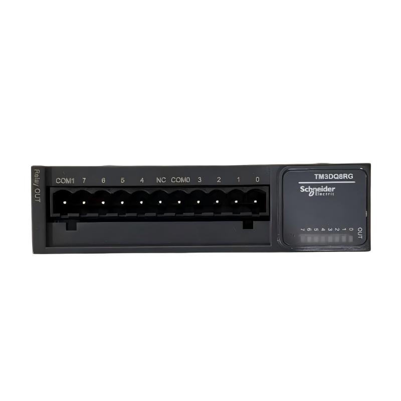
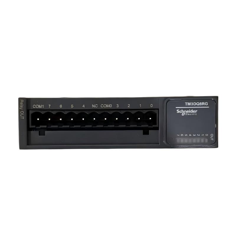
The Schneider Electric TM3DQ8RG is an 8-channel discrete output expansion module designed for industrial automation systems using compatible Modicon programmable logic controllers (PLCs). As part of the Modicon TM3 series, it provides relay-based switching for controlling external electrical circuits in machine automation, production equipment, and industrial control panels.
The TM3DQ8RG features eight normally open relay outputs. Unlike transistor output modules, which use semiconductor switching and are generally intended for specific DC control circuits, relay outputs provide electrical contacts that can switch compatible AC or DC loads within their specified ratings. This makes the TM3DQ8RG a practical option for applications requiring relay contacts rather than dedicated PNP or NPN transistor outputs.
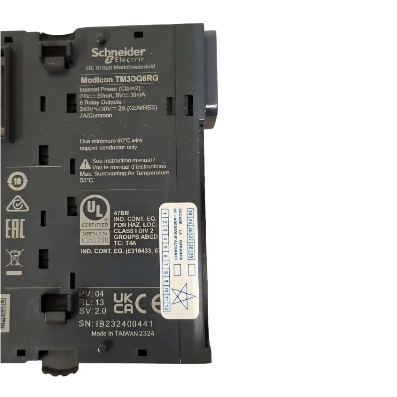
The module supports rated output voltages of 24 V DC and 240 V AC, with a rated current of 2 A per output. Its relay contacts can be used to switch suitable indicator circuits, interface relays, control circuits, and other compatible electrical loads. Actual switching capability depends on the voltage, current, load type, and switching frequency. Inductive loads require particular attention to protective circuits and contact-life limitations.
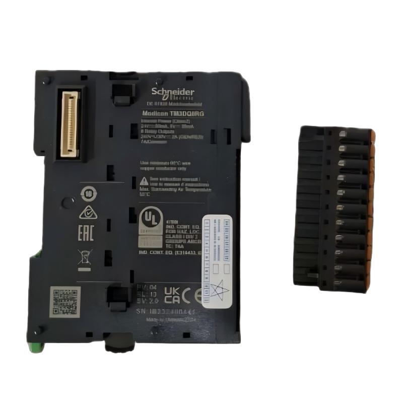
One of the main features of the TM3DQ8RG is its removable spring-clamp terminal block. This connection design supports convenient wiring and maintenance in industrial control cabinets. The spring terminals provide a practical alternative to screw-terminal versions when the installation requires a spring-clamp connection method.
The TM3DQ8RG has eight output channels arranged into two groups, with four channels sharing a common line in each group. The two common lines are not internally connected. This arrangement provides flexibility when designing output circuits, but each group must be wired according to the required supply and load configuration.
The module is designed for compatible Modicon M221, M241, M251, and M262 controllers. It connects to the PLC through the Modicon TM3 expansion interface, allowing the controller to coordinate the relay outputs with sensor inputs, timers, interlocks, and machine-sequence logic.
Each output channel has a green LED indicator to help technicians observe its status. This is useful during commissioning and troubleshooting, although an illuminated LED does not independently confirm that the external load is operating correctly.
With dimensions of approximately 90 × 84.6 × 27.4 mm and a weight of approximately 0.11 kg, the Schneider TM3DQ8RG provides eight relay output points in a compact housing. It is suitable for many control-panel applications where relay-based switching and modular PLC expansion are required.
2. Technical Specifications
| Parameter | Specification |
|---|---|
| Brand | Schneider Electric |
| Model | TM3DQ8RG |
| Product Series | Modicon TM3 |
| Product Type | Discrete Output Expansion Module |
| Number of Output Channels | 8 |
| Output Technology | Electromechanical relay |
| Contact Type | Normally open (NO) |
| Rated Output Voltage | 24 V DC / 240 V AC |
| Maximum Output Voltage | 30 V DC / 264 V AC |
| Rated Output Current | 2 A per output |
| Maximum Current per Common | 7 A |
| Output Group Arrangement | 2 common groups, 4 channels per group |
| Connection Type | Removable spring-clamp terminal block |
| Minimum Switching Load | 5 V DC at 10 mA |
| Maximum Switching Frequency at Maximum Load | 20 operations per minute |
| Maximum Turn-On Time | 10 ms |
| Maximum Turn-Off Time | 10 ms |
| Contact Resistance | 30 mΩ maximum |
| Mechanical Durability | 20 million operations |
| Short-Circuit Protection | Not provided |
| Isolation Between Output and Internal Logic | 500 V AC |
| Isolation Between Output Groups | 1500 V AC |
| Maximum Cable Length | 30 m with unshielded cable, subject to installation requirements |
| Status Indication | One green LED per output channel |
| Compatible Controller Families | Supported Modicon M221, M241, M251, and M262 controllers |
| Mounting | Compatible DIN rail or approved panel-mounting arrangement |
| Protection Rating | IP20 |
| Operating Temperature | -10°C to +55°C |
| Dimensions | 90 × 84.6 × 27.4 mm |
| Weight | Approximately 0.11 kg |
| Typical Application | Industrial relay output switching |
The specifications above summarize the main characteristics of the TM3DQ8RG. The 2 A per-output rating does not mean that every channel can operate at 2 A without regard to the common-line limit, load type, and switching frequency. Each common line has a maximum current of 7 A, and the application must comply with all relevant output limitations.
The module does not provide built-in short-circuit protection. Appropriate external circuit protection must be selected according to the wiring design and the manufacturer’s instructions.
Relay outputs can also be damaged by unsuitable inductive or capacitive loads. Follow the manufacturer’s recommendations for protective circuits, particularly when switching relay coils, solenoids, or other inductive devices.
3. Function and Working Principle
3.1 Relay-Based Digital Output Control
The primary function of the TM3DQ8RG is to convert digital commands from a compatible PLC into relay switching actions. The PLC program determines whether an output channel should be activated based on input signals, operating conditions, timers, and programmed sequence logic.
When the PLC commands a channel to switch on, the corresponding relay operates and changes the state of its normally open contact. This closes the contact and allows the external circuit to operate, provided that the load circuit has been correctly wired and supplied.
When the PLC deactivates the output, the relay returns to its normal state and the contact opens. The connected circuit is then interrupted, subject to the behavior of the external device and the overall electrical design.
This mechanism allows the TM3DQ8RG to control a range of suitable electrical circuits without requiring the connected load to use the same switching technology as a transistor output module.
3.2 Normally Open Relay Contacts
All eight output channels use normally open relay contacts. In the de-energized state, each contact is open. When the relay is activated, the contact closes and establishes the electrical connection.
This arrangement is commonly used for control commands that need to be switched on or off by the PLC. Examples include activating a signal circuit, enabling an interface relay, or controlling a compatible auxiliary device.
The contact rating must be considered carefully. Although the module supports rated voltages of 24 V DC and 240 V AC, its switching capability varies according to the load type and electrical conditions. An inductive load can place different demands on the relay contacts compared with a resistive load.
The TM3DQ8RG should not be regarded as a universal power-switching device. Loads must remain within the manufacturer’s specified voltage, current, and switching limits.
3.3 Supporting AC and DC Control Circuits
One advantage of relay outputs is their ability to switch suitable AC or DC circuits. The TM3DQ8RG supports rated output voltages of 24 V DC and 240 V AC.
This makes it useful in control systems that combine different types of electrical circuits. For example, a PLC may use one output to switch a 24 V DC interface circuit and another to switch a compatible AC control circuit, provided that the circuit design, common-group wiring, and electrical ratings permit the arrangement.
The output contacts must not be used beyond their specified maximum voltage or current. The choice of external protective devices and wiring must also account for the circuit voltage and load characteristics.
3.4 Two Common Output Groups
The TM3DQ8RG organizes its eight outputs into two groups. Each group contains four output channels that share a common line. The two common lines are not internally connected.
This arrangement is important when planning the cabinet wiring. The common connections must be wired according to the intended circuit design, and the maximum current per common line must not exceed 7 A.
Engineers should identify which channels belong to each group before connecting the field wiring. Proper group planning can help prevent wiring errors and simplify maintenance.
3.5 Relay Operation and Response Time
Relay outputs use electromechanical contacts, so their switching behavior differs from that of semiconductor outputs. The TM3DQ8RG has a maximum turn-on time of 10 ms and a maximum turn-off time of 10 ms under the specified conditions.
These response characteristics are suitable for many standard machine-control functions, including status signaling, sequence control, and switching of compatible auxiliary circuits.
However, relay outputs are generally less suitable than transistor outputs for very high-frequency switching. At the maximum rated load, the specified switching frequency is limited to 20 operations per minute. Applications that require frequent repetitive switching should therefore be evaluated carefully before selecting this module.
3.6 Output Status Indication
Each channel has a green LED indicator. The indicator helps the technician determine whether the corresponding output has been activated.
During commissioning, the LEDs can be used to compare the expected PLC output state with the module’s local indication. If a connected device does not respond, the technician can inspect the output status, terminal wiring, external supply, and load circuit.
The LED does not guarantee that the relay contact is conducting correctly or that the downstream device has operated. If the status indicator and field-device behavior do not match, further electrical testing may be necessary.
4. Role in Industrial Control Systems
4.1 Expanding PLC Output Capacity
Industrial automation projects often require more output points as machines gain additional functions. The TM3DQ8RG provides eight additional relay output channels for a compatible Modicon TM3 system.
These channels can be assigned to control signals, indicators, interface relays, and other compatible loads. The module allows engineers to expand the available output capacity while retaining the existing PLC architecture, provided that the controller supports the proposed expansion arrangement.
The maximum number of expansion modules depends on the controller model and the applicable system configuration. These limits should be checked during the control-panel design stage.
4.2 Interfacing Control Logic with External Circuits
The PLC program operates using logical conditions and output variables, while field equipment requires electrical contacts or signals to respond. The TM3DQ8RG provides a relay interface between the PLC’s control logic and compatible external circuits.
For example, the PLC may activate an output after a sensor detects a product or when a machine reaches a specified step. The corresponding relay contact closes, allowing the external circuit to perform the commanded function.
This separation between control logic and field switching can make the system easier to organize, troubleshoot, and maintain.
4.3 Supporting Machine Sequences
Automated machinery commonly operates through a sequence of steps, such as loading, clamping, processing, transferring, and unloading. The PLC uses sensor feedback and program logic to determine when each step should begin.
The TM3DQ8RG can switch suitable relay circuits associated with these operations. The PLC decides when to activate each channel, while the relay contacts provide the corresponding switching action.
For loads requiring higher current or more specialized switching, an additional contactor, interface relay, or other appropriately rated device may still be necessary.
4.4 Switching Different Types of Control Loads
Relay contacts can be useful when a control system must switch compatible AC and DC circuits. The TM3DQ8RG can accommodate suitable loads within its specified ratings and circuit arrangement.
However, engineers must consider the electrical properties of the load. Resistive, inductive, and capacitive loads place different demands on relay contacts. Capacitive loads are not supported by the module, and inductive loads require appropriate protective circuits.
Selecting the correct output module and protective arrangement helps improve reliability and reduce the risk of contact damage.
4.5 Simplifying Maintenance and Diagnostics
The individual output LEDs help maintenance personnel identify active channels. Clear terminal labeling and a documented channel-to-device mapping make the module easier to inspect during service.
When a device fails to operate, the technician can check the PLC command, the corresponding LED, the relay circuit, the common connection, and the external power supply. This process helps distinguish control-program issues from wiring faults or failures in the downstream equipment.
The module’s spring-clamp terminals also support convenient wiring and can simplify certain maintenance tasks when conductors must be inspected or reconnected.
5. Industrial Applications
5.1 Packaging Machinery
Packaging machines often use digital outputs to activate indicators, command interface relays, control auxiliary circuits, and coordinate machine steps.
The TM3DQ8RG can switch suitable AC or DC control circuits within its specified ratings. The PLC can activate the outputs according to product position, timer conditions, and operating sequence.
For pneumatic valves, larger actuators, or other loads with significant current demand, the output may need to control an appropriately rated interface rather than drive the load directly.
5.2 Conveyor and Material-Handling Systems
Conveyor systems may contain transfer stations, sorting mechanisms, warning indicators, auxiliary relays, and control interfaces.
The TM3DQ8RG can provide relay contacts for compatible circuits used in these systems. For example, the PLC may activate a relay output when a sensor detects a product at a designated position.
The module should not be assumed to drive a conveyor motor directly. Motors normally require suitable motor starters, contactors, or drives designed for the motor’s electrical requirements.
5.3 Assembly and Production Lines
Assembly machinery may require multiple output channels to coordinate clamps, fixtures, status indicators, and interface circuits between stations.
The TM3DQ8RG provides eight relay outputs for suitable switching tasks. The PLC can control these outputs based on sensor signals, process conditions, and programmed sequence logic.
Its modular design allows the output module to be installed alongside compatible input and expansion modules in a control cabinet.
5.4 Industrial Control Panels
Control panels frequently use relay outputs to switch auxiliary circuits, indicator devices, and compatible external control equipment.
The TM3DQ8RG can be incorporated into a supported Modicon TM3 configuration. Its removable spring-clamp terminals provide a practical wiring method for cabinet builders who prefer spring connections.
The module’s IP20 protection rating means that it should be installed inside a suitable enclosure rather than exposed directly to environmental conditions beyond its intended use.
5.5 Water and Utility Equipment
Utility-control systems may require relay outputs for compatible valve interfaces, alarms, auxiliary relays, and status circuits.
The TM3DQ8RG can be used when the load voltage, current, switching frequency, and load type remain within the documented limits. Any higher-current equipment should be controlled through an appropriately rated interface.
When switching solenoid valves or other inductive loads, use suitable suppression components to reduce voltage transients and protect the relay contacts.
5.6 HVAC and Building Equipment
HVAC and facility-control panels may use PLC outputs to switch compatible auxiliary relays, status lamps, alarms, and other control circuits.
The TM3DQ8RG can provide the required relay contacts where its electrical ratings match the application. Engineers should verify the receiving circuit’s voltage, current, and load characteristics before connection.
The common-group arrangement should also be considered when different circuits are connected to the module.
5.7 Alarm and Status Signaling
Relay outputs can be used to activate suitable external alarm circuits, status indicators, and control interfaces. The PLC may switch an output when a process step finishes, an alarm condition occurs, or a machine changes operating state.
Using documented output assignments and consistent labeling helps technicians understand the function of each channel and reduces the risk of wiring errors during maintenance.
6. Installation and System Integration
6.1 Verify Controller Compatibility
Before installation, confirm that the host PLC supports the Modicon TM3 expansion system and the proposed module arrangement.
The TM3DQ8RG is designed for supported Modicon M221, M241, M251, and M262 controllers. Exact compatibility should be checked against the controller reference, firmware requirements, and the expansion limits specified for the system.
A module’s physical fit does not by itself guarantee that the controller configuration will support it.
6.2 Mounting and Cabinet Layout
The TM3DQ8RG measures approximately 90 mm in height, 84.6 mm in depth, and 27.4 mm in width. It can be installed using a compatible DIN rail or an approved panel-mounting arrangement, following the manufacturer’s instructions.
Provide sufficient space for terminal access, conductor routing, ventilation, and maintenance. The enclosure should be designed to protect the module from environmental conditions outside its IP20 rating.
The module should be securely mounted before the terminal wiring is completed.
6.3 Spring-Terminal Wiring
The TM3DQ8RG uses a removable spring-clamp terminal block. Conductors must be prepared and inserted according to the manufacturer’s specified wire-size range and wiring instructions.
Ensure that each conductor is fully inserted and securely retained. Use appropriate wire ferrules where required by the conductor type and installation practice, and label conductors clearly.
The spring-terminal connection can simplify installation, but it does not remove the need for correct conductor sizing, routing, and electrical protection.
6.4 Wiring the Two Common Groups
The module has two common lines, each serving four output channels. The common lines are not internally connected.
Before wiring, identify the channels associated with each group and determine the correct supply and load arrangement. Do not assume that the two common lines are electrically connected inside the module.
The maximum current per common line is 7 A. The total load current on each group must remain within this limit, and the current rating of each individual output must also be respected.
6.5 Load Selection and Electrical Protection
Each relay output is rated at 2 A, subject to the specified voltage, load type, and switching limitations. The maximum output voltage is 30 V DC or 264 V AC, while the rated operating voltages include 24 V DC and 240 V AC.
The module does not provide built-in short-circuit protection. Appropriate external protective devices must therefore be selected for the output circuits and installed according to the electrical design.
Inductive loads can generate voltage transients when the contacts open. The manufacturer’s guidance recommends appropriate protection, such as a freewheeling diode for suitable DC inductive loads or an RC snubber for suitable AC inductive loads.
Capacitive loads are not supported. Before connecting a device, verify that its electrical characteristics and switching requirements are compatible with the relay output.
6.6 PLC Configuration and Programming
After mounting and wiring, configure the module in the supported PLC engineering environment. Confirm that the controller recognizes the expansion hardware and that the output addresses match the project configuration.
Assign meaningful names to output variables and document the device connected to each channel. Program interlocks and fault-handling logic as required by the machine design.
Before normal operation, test each output individually and confirm that the correct external circuit responds. The relay’s status LED should be checked together with the actual field-device behavior.
6.7 Commissioning and Maintenance
Commissioning should include checks of the mounting, terminal connections, common-group wiring, output voltage, load current, and external protective devices.
For maintenance, inspect the spring terminals, wiring insulation, and connected loads. If a channel does not work correctly, check the PLC command, output indicator, common connection, external supply, and relay contact circuit.
Relay contacts have a finite electrical life, and their durability depends on the load type and switching conditions. Frequent switching or unsuitable inductive loads can shorten contact life.
All electrical work should follow the site’s isolation and safety procedures and be performed by qualified personnel.
7. Compatible System Components
The TM3DQ8RG is intended for use in a compatible Modicon TM3 automation system. The following table lists common component categories that may be used alongside the module. Exact compatibility depends on the controller, system configuration, and electrical design.
| Component Category | Function in the System |
|---|---|
| Modicon M221 PLC | Executes control logic and supports compatible TM3 expansion |
| Modicon M241 PLC | Provides PLC control for supported automation applications |
| Modicon M251 PLC | Supports compatible machine-control and networked automation configurations |
| Modicon M262 PLC | Provides controller functionality in supported automation architectures |
| Modicon TM3 Digital Input Modules | Receive signals from sensors, switches, and discrete field devices |
| Modicon TM3 Analog I/O Modules | Handle compatible analog signals where required |
| 24 V DC Power Supply | Supplies power to suitable control circuits |
| External AC or DC Supplies | Power compatible loads according to the circuit design |
| Interface Relays | Provide an intermediate switching stage when required |
| Contactors and Motor Starters | Control higher-power equipment within their specified ratings |
| Industrial Sensors | Provide process and machine feedback through suitable input modules |
| Indicator Lamps and Alarm Devices | Display operating states and alarm conditions |
| Protective Devices | Protect external circuits according to the electrical design |
| Engineering Software | Supports PLC programming, configuration, diagnostics, and maintenance |
The TM3DQ8RG is a relay output expansion module rather than a standalone controller. Its function depends on a compatible PLC, the TM3 expansion connection, correctly wired output groups, and appropriately protected field circuits.
8. Recommended Alternative Models
The best alternative depends on the required output count, terminal type, switching technology, and electrical load.
| Model or Model Family | Main Difference | Selection Consideration |
|---|---|---|
| Schneider TM3DQ8R | 8 relay outputs with removable screw terminals | Consider when the relay function is suitable but screw terminals are preferred |
| Schneider TM3DQ8RG | 8 relay outputs with removable spring terminals | Reference model for applications requiring spring-terminal wiring |
| Schneider TM3DQ16RG | 16 relay outputs with spring terminals | Consider when more relay output channels are needed; verify cabinet and controller limits |
| Schneider TM3DQ16R | 16 relay outputs with screw terminals | Consider when more channels and screw-terminal wiring are required |
| Schneider TM3 Transistor Output Modules | Electronic transistor switching rather than relay contacts | Consider when the application requires faster or more frequent switching and the load is compatible |
These models are not automatically interchangeable. Relay output modules and transistor output modules have different electrical characteristics, and terminal arrangements may differ even when the modules belong to the same product family.
Before selecting a replacement, verify the output count, contact type, voltage and current ratings, common-group arrangement, terminal style, controller compatibility, and installation requirements.
9. Key Advantages of the Schneider TM3DQ8RG
9.1 Eight Relay Output Channels
The TM3DQ8RG provides eight discrete relay outputs in one compact expansion module. This can help increase the output capacity of a compatible PLC system without adding a separate controller for each function.
9.2 Support for Compatible AC and DC Circuits
The relay contacts support rated output voltages of 24 V DC and 240 V AC, subject to the specified operating limits. This makes the module useful in control systems that need to switch suitable AC or DC circuits.
9.3 Removable Spring-Clamp Terminals
The spring-terminal design supports convenient conductor installation and maintenance. The removable terminal block can also simplify certain servicing tasks where the wiring assembly needs to be disconnected.
9.4 Normally Open Relay Contacts
The eight normally open contacts provide a straightforward switching arrangement for suitable control and signaling circuits.
9.5 Individual Channel Status Indicators
Each output channel has a green LED that helps technicians observe output activity during commissioning and troubleshooting.
9.6 Modular Modicon TM3 Integration
The module is designed for supported Modicon controllers, allowing additional relay output points to be incorporated into a compatible control architecture.
9.7 Compact Housing
With dimensions of approximately 90 × 84.6 × 27.4 mm, the module can be incorporated into a compact control cabinet while providing eight relay output channels.
9.8 Defined Output Group Arrangement
The two common groups, each serving four channels, provide a clear structure for organizing field wiring. Correct group planning helps support an orderly and maintainable cabinet layout.
9.9 Mechanical Durability
The relay contacts have a specified mechanical durability of 20 million operations. Actual electrical life depends on the voltage, current, load type, and switching conditions.
10. Technical FAQs
Q1: What is the Schneider TM3DQ8RG?
The Schneider Electric TM3DQ8RG is a Modicon TM3 discrete output expansion module with eight normally open relay outputs and removable spring-clamp terminals.
Q2: How many output channels does it provide?
The module provides eight relay output channels.
Q3: What output voltages does the TM3DQ8RG support?
Its rated output voltages include 24 V DC and 240 V AC. The maximum specified voltages are 30 V DC and 264 V AC. The actual load must remain within the applicable switching ratings.
Q4: What is the rated current per output?
Each output is rated at 2 A, subject to the specified load and operating conditions. Each common line has a maximum current of 7 A.
Q5: How are the outputs grouped?
The eight outputs are arranged into two groups, with four channels sharing one common line in each group. The two common lines are not internally connected.
Q6: Does the TM3DQ8RG use relay or transistor outputs?
It uses electromechanical relay outputs. This distinguishes it from transistor output modules in the Modicon TM3 family.
Q7: What is the difference between TM3DQ8RG and TM3DQ8R?
Both are 8-channel relay output modules. The TM3DQ8RG uses removable spring-clamp terminals, while the TM3DQ8R uses removable screw terminals.
Q8: Which PLCs are compatible with the TM3DQ8RG?
It is designed for supported Modicon M221, M241, M251, and M262 controllers. Verify the exact controller reference and supported expansion configuration before installation.
Q9: Does the module have built-in short-circuit protection?
No. The TM3DQ8RG does not provide built-in short-circuit protection. Appropriate external protection must be selected and installed according to the manufacturer’s instructions.
Q10: Can the module switch inductive loads?
It can switch suitable inductive loads only within the specified electrical limits and with appropriate protective circuits. Inductive loads can produce voltage transients that may damage relay contacts if not properly suppressed.
Q11: Can the TM3DQ8RG switch capacitive loads?
The module documentation states that capacitive loads are not supported. A different switching arrangement should be evaluated for such applications.
Q12: What is the maximum cable length?
The specified maximum cable length is 30 m for unshielded relay-output wiring, subject to the manufacturer’s installation requirements.
Q13: What is the protection rating?
The module has an IP20 protection rating and should be installed inside a suitable enclosure for the intended environment.
Q14: What are the dimensions and weight?
The module measures approximately 90 × 84.6 × 27.4 mm and weighs approximately 0.11 kg.
Q15: What is the mechanical life of the relay contacts?
The specified mechanical durability is 20 million operations. Electrical life depends on the switching voltage, current, load type, and frequency of operation.
Q16: Can the TM3DQ8RG replace a transistor output module?
Not as a direct electrical equivalent. Relay and transistor outputs operate differently and have different switching characteristics. Confirm that the receiving circuit, load requirements, and program configuration are suitable before changing output technology.
11. Conclusion
The Schneider Electric TM3DQ8RG is an 8-channel relay output expansion module designed for compatible Modicon TM3 automation systems. Its normally open relay contacts, support for suitable AC and DC circuits, removable spring-clamp terminals, and individual channel status LEDs make it a practical option for many industrial control applications.
The module can be used in packaging machinery, assembly equipment, material-handling systems, production lines, and control panels that require additional relay output points. Its modular design supports expansion of a compatible PLC system while keeping the output wiring organized.
Successful integration depends on observing the 2 A per-output rating, the 7 A common-line limit, the two-group wiring arrangement, and the specified load restrictions. Because the module has no built-in short-circuit protection and does not support capacitive loads, appropriate external protection and correct load selection are essential.
For automation engineers, maintenance teams, and industrial equipment buyers, the TM3DQ8RG provides a compact relay-based output solution within the Modicon TM3 platform. Confirming the exact model, terminal type, electrical ratings, and wiring requirements before purchase or replacement helps ensure reliable integration into the intended control system.