

ProductPRODUCT
Featured products

Contact Us
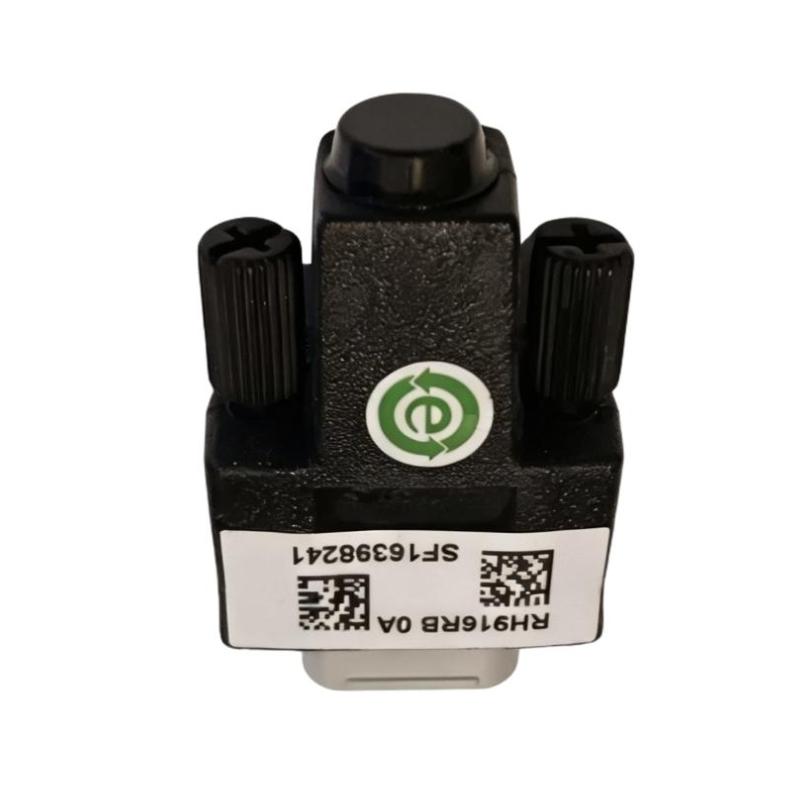
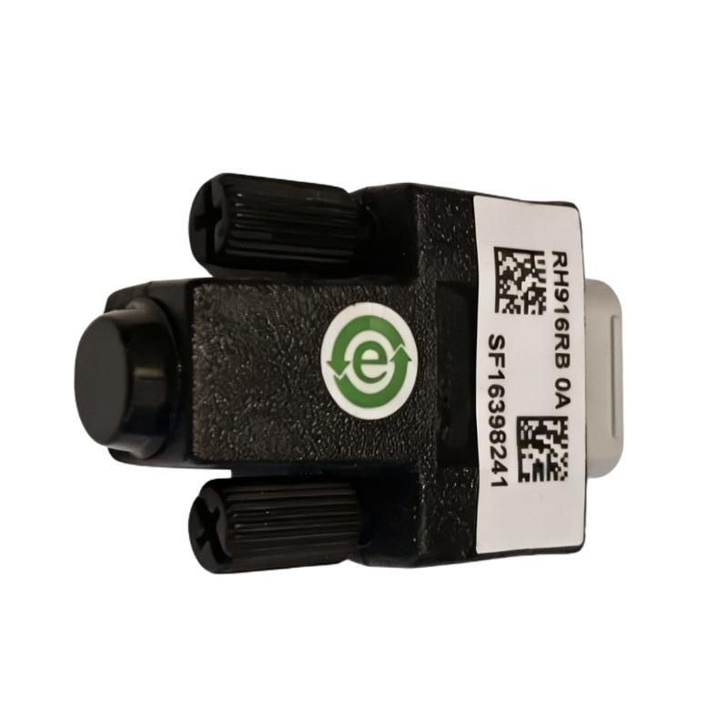
- Foxboro
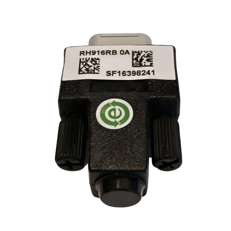
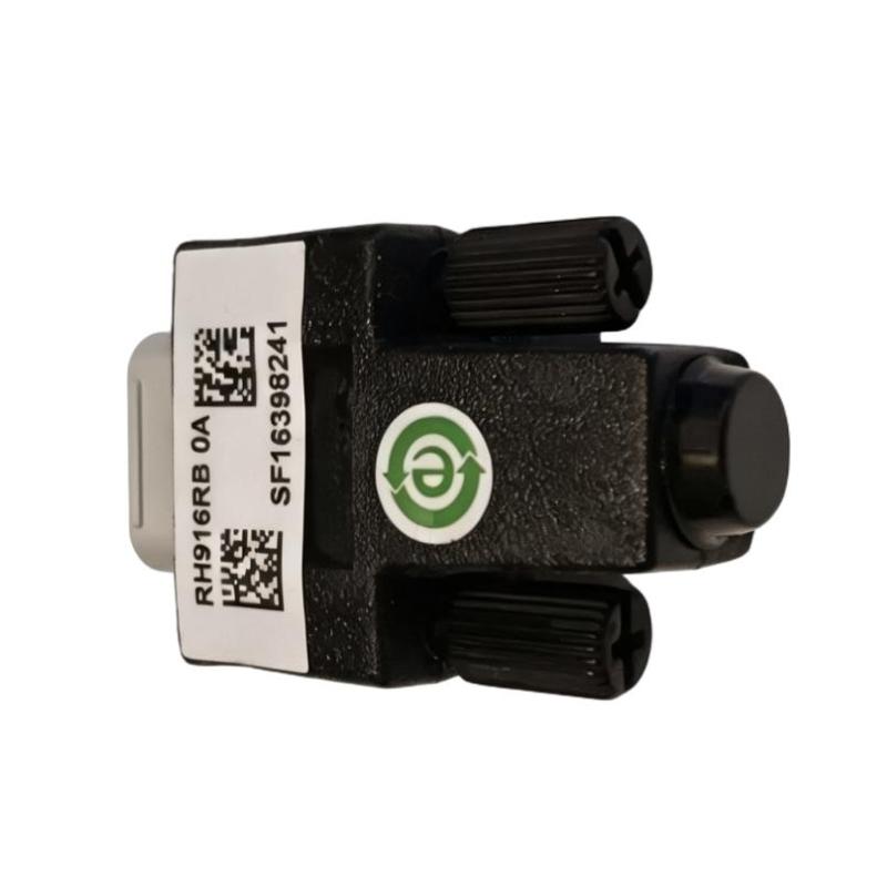
- RH916RB
- Fieldbus Backplane Termination Connector
- USA
- 9 Pin
- 0.1 kg
- Xiamen, China
- New & In Stock
- T/T, PayPal, Western Union
- 1 Year
- 1-3 Working Days
- DHL, UPS, TNT, FedEx and EMS.
- 24-Hour Service
- COO
- 74
Our advantage

Global Logistics
We have a 10-year logistics and express cooperation agreement, so our products can be shipped to any place in the world.

Brand new and original
Our products are imported in bulk from the place of origin. Because of the cooperative relationship, our products are all original and 100% new.

24-hour service
We provide 7*24 hours service to our customers. We will be there whenever you need us.

Price advantage
All our products are priced very favorably because we have our own warehouse and supply.
| Company Information | |||
| [email protected] | |||
| Mobile | +8615980777398 | ||
| +8615980777398 | |||
| 15980777398 |
Product Overview
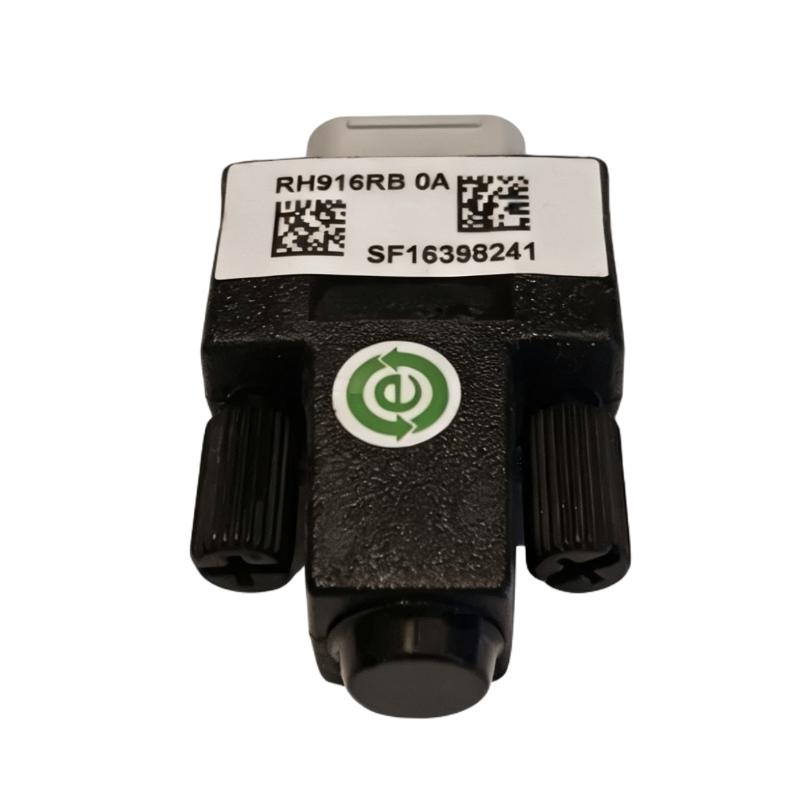
The Foxboro RH916RB Fieldbus Backplane Termination Connector is a dedicated termination component designed for compatible Foxboro industrial control and distributed control system fieldbus architectures. It is used to provide the required termination at the appropriate endpoint of a fieldbus or baseplate communication segment.
The RH916RB is a passive component rather than an active controller or communication processor. It does not execute control logic, process analog signals, or perform I/O conversion. Its purpose is to establish the correct electrical termination of the communication path so that fieldbus signals can travel reliably between the control processor and connected baseplates or fieldbus modules.
In a typical installation, the RH916RB is positioned at the end of the applicable fieldbus chain. Correct termination is important because an improperly terminated communication segment can experience signal-integrity problems. Depending on the system configuration, symptoms may include intermittent communication, fieldbus alarms, module dropouts, communication retries, or loss of communication with multiple devices.
The supplied product information is:
- Manufacturer: Foxboro
- Model: RH916RB
- Product Type: Fieldbus Backplane Termination Connector
- Connector: 9 Pin
- Weight: 0.1 kg
- Primary Function: Fieldbus/Baseplate Termination
- Application: Foxboro DCS and Industrial Automation Systems
- Component Type: Passive Fieldbus Termination Device
The RH916RB is also associated with newer Foxboro configurations in which it replaces the earlier P0916RB designation. When replacing an older termination component, technicians should verify the exact system configuration and approved replacement relationship before installation.
Technical Specifications
| Parameter | Specification |
|---|---|
| Manufacturer | Foxboro |
| Model Number | RH916RB |
| Product Type | Fieldbus Backplane Termination Connector |
| Connector Type | 9 Pin |
| Weight | 0.1 kg |
| Main Function | Fieldbus Termination |
| Application | Industrial DCS |
| Network Function | Physical-Layer Termination |
| Installation Position | Designated Fieldbus Endpoint |
| Component Category | Passive Connector / Terminator |
| Typical System Role | Baseplate Fieldbus Termination |
| Maintenance Application | Replacement, Inspection, Troubleshooting |
The supplied product information specifies a 9-pin connector and a weight of 0.1 kg.
Function and Working Principle
The RH916RB provides termination at the designated end of an applicable fieldbus communication segment.
A simplified network can be represented as:
Control Processor
↓
Fieldbus Connection
↓
Baseplate 1
↓
Baseplate 2
↓
Baseplate 3
↓
RH916RB Termination
The terminator provides the electrical endpoint required by the fieldbus architecture.
Digital communication signals travel through a transmission medium. At the end of the transmission line, an improperly terminated connection can cause unwanted signal reflections. These reflections can interfere with the original communication signal and reduce the reliability of data transmission.
The RH916RB helps establish the appropriate termination condition.
Its function can therefore be summarized as:
Controller
→ Fieldbus Transmission
→ Baseplate Communication
→ Final Network Point
→ RH916RB Termination
A correctly installed termination component helps the communication network maintain stable signal conditions.
Role in Foxboro Control Systems
Foxboro DCS installations can contain:
- Field Control Processors
- Fieldbus Control Modules
- Fieldbus Modules
- Modular baseplates
- Compact baseplates
- Communication cables
- Redundant communication paths
- Fieldbus termination components
The RH916RB is associated with the physical fieldbus/baseplate communication infrastructure.
In an appropriate configuration, the terminator can be located at the end of the baseplate daisy chain.
For example:
Field Control Processor
↓
Fieldbus Cable
↓
Baseplate A
↓
Baseplate B
↓
Baseplate C
↓
RH916RB
The termination point must correspond to the actual system topology.
This is particularly important when a system has been expanded or modified. Adding another baseplate may change the physical endpoint of the fieldbus, requiring the termination arrangement to be reviewed.
RH916RB and P0916RB Relationship
The RH916RB is associated with the newer Foxboro product designation for the fieldbus baseplate terminator function.
In existing installations, technicians may encounter P0916RB while working with older system documentation or installed hardware.
When replacing an older component, the following should be verified:
- Existing model number
- Current system generation
- Baseplate type
- Fieldbus architecture
- Connector configuration
- Approved replacement arrangement
The physical appearance of two components alone should not be used as the basis for determining interchangeability.
Fieldbus Termination Principle
Correct termination depends on the physical topology of the communication system.
A basic single-ended arrangement can be represented as:
Controller → Fieldbus → Baseplates → Terminator
The RH916RB should be installed at the intended endpoint of the applicable segment.
Incorrect termination may include:
- Terminator missing
- Terminator installed at the wrong location
- Loose termination connector
- Damaged termination component
- Incorrect network topology
- Unintended additional termination
These conditions can lead to unstable communication.
Industrial Applications
The RH916RB can be used in compatible Foxboro industrial control installations involving fieldbus-connected baseplates and I/O infrastructure.
Typical applications include:
Process Automation
Used within distributed control systems for industrial process monitoring and control.
Chemical Processing
Suitable for fieldbus infrastructure supporting distributed I/O in process plants.
Oil and Gas
Can be part of the fieldbus/baseplate communication architecture in automation systems used for process control.
Power Generation
May be used in DCS installations where fieldbus-connected I/O modules communicate with control processors.
Water and Wastewater
Applicable to industrial automation systems using distributed fieldbus I/O.
Manufacturing
Can support communication infrastructure in process and discrete industrial automation environments.
Installation Guide
1. Verify the RH916RB
Before installation, verify that the replacement component is:
Foxboro RH916RB
Fieldbus Backplane Termination Connector
Check:
- Part number
- Connector type
- Physical condition
- Mating interface
- Intended installation position
Make sure the component has not been damaged during storage or transportation.
2. Review the Existing Fieldbus Topology
Before removing an existing terminator, identify the complete communication path.
Determine:
- Control processor location
- Fieldbus cable route
- Number of connected baseplates
- Final baseplate
- Existing termination location
- Any redundant communication arrangement
Do not assume that the physically closest connector is the correct termination position.
3. Place the System in a Safe Maintenance State
Fieldbus termination work can affect communication with multiple I/O devices.
Before beginning maintenance:
- Follow the plant maintenance procedure.
- Put affected equipment into an appropriate operating state.
- Apply required isolation procedures.
- Prevent unintended restart.
- Confirm that affected control loops are safe to work on.
The exact shutdown requirements depend on the plant and control-system architecture.
4. Record the Existing Configuration
Before disconnecting the existing component, record its position.
Recommended information includes:
- Baseplate identification
- Connector position
- Fieldbus cable routing
- Terminator position
- Nearby modules
- Any redundant connection arrangement
Clear documentation can prevent configuration errors during reassembly.
5. Remove the Existing Terminator
Carefully remove the existing termination connector.
Avoid:
- Pulling on cables
- Excessive force
- Twisting the connector
- Touching contacts unnecessarily
- Dropping the component into the cabinet
After removal, inspect the old component.
6. Inspect the Mating Connector
Inspect the baseplate-side connection carefully.
Look for:
- Bent pins
- Damaged contacts
- Dirt
- Dust
- Corrosion
- Mechanical deformation
- Loose mounting hardware
A defective mating connector can create the same symptoms as a defective RH916RB.
7. Inspect the Fieldbus Cable
Check the nearby fieldbus cable.
Inspect for:
- Damaged insulation
- Cuts
- Crushing
- Excessive bending
- Loose connections
- Mechanical stress
- Improper routing
If the cable has been damaged, replacing the terminator alone may not resolve the communication problem.
8. Install the RH916RB
Align the RH916RB carefully with the mating interface.
Confirm:
- Correct orientation
- Correct alignment
- Full connector engagement
- Proper mechanical seating
Do not force the component into place.
9. Verify the Termination Position
After installation, verify that RH916RB is located at the correct endpoint of the fieldbus segment.
This is one of the most important commissioning checks.
A correctly functioning terminator installed in the wrong location can still produce network problems.
10. Secure the Connection
If the applicable installation uses retaining hardware, ensure that it is properly secured.
Avoid excessive tightening that could damage the connector or mounting structure.
11. Inspect the Complete Communication Path
Before restoring the system, check:
- Fieldbus cables
- Baseplate connectors
- Termination connector
- Cable routing
- Mechanical connections
- Network topology
This provides an opportunity to identify problems introduced during maintenance.
Commissioning Procedure
Step 1 — Perform a Visual Inspection
Confirm that the RH916RB is correctly installed.
Step 2 — Verify Connector Seating
Make sure the 9-pin connector is completely engaged.
Step 3 — Verify Fieldbus Topology
Confirm that the termination remains at the intended endpoint.
Step 4 — Restore the System
Restore the affected system according to the plant’s approved procedure.
Step 5 — Check Communication
Observe the control system for:
- Communication alarms
- Fieldbus faults
- Module dropouts
- Repeated communication errors
- Unexpected diagnostic messages
Step 6 — Verify Baseplates
Confirm that all expected baseplates are communicating normally.
Step 7 — Verify I/O Modules
Check communication with connected fieldbus modules.
Step 8 — Monitor Stability
Continue observing the system long enough to identify intermittent faults.
Troubleshooting Guide
Problem 1: Multiple Fieldbus Modules Lose Communication
When multiple modules lose communication at the same time, investigate the shared fieldbus infrastructure first.
Possible causes include:
- Missing RH916RB
- Incorrect termination position
- Loose connector
- Damaged fieldbus cable
- Baseplate communication fault
- Controller communication fault
- Incorrect topology
Recommended Procedure
- Identify the affected modules.
- Determine whether they share the same fieldbus segment.
- Inspect the termination.
- Check the RH916RB position.
- Inspect fieldbus cables.
- Check baseplate connections.
- Review system diagnostics.
Problem 2: Intermittent Fieldbus Communication
Intermittent communication can be caused by:
- Loose connector
- Poor contact
- Damaged termination component
- Damaged fieldbus cable
- Mechanical vibration
- Electrical interference
- Incorrect network topology
Because intermittent problems can disappear temporarily, inspect the physical installation carefully even if the system appears normal during testing.
Problem 3: Complete Loss of Fieldbus Communication
Potential causes include:
- Missing terminator
- Incorrect RH916RB installation
- Disconnected fieldbus cable
- Damaged connector
- Baseplate fault
- Controller communication fault
- Power-related issue
Begin diagnosis at the physical layer.
Problem 4: Communication Problems Start After Maintenance
If the fieldbus was working correctly before maintenance and fails immediately afterward, first check the work that was performed.
Inspect:
- RH916RB installation
- Connector seating
- Fieldbus cable connections
- Baseplate connections
- Termination position
- Any wiring modifications
Compare the post-maintenance configuration with the original configuration.
Problem 5: Only One Baseplate Stops Communicating
If only one baseplate is affected, possible causes include:
- Local connector fault
- Cable fault
- Baseplate hardware fault
- Local communication interface fault
- Mechanical connection problem
The RH916RB should not automatically be replaced unless the diagnostic evidence points toward the termination.
Problem 6: Several Baseplates Become Unstable
Possible causes include:
- Termination problem
- Fieldbus cable issue
- Network topology problem
- Loose communication connection
- Electrical interference
- Baseplate communication fault
If several adjacent devices are affected, investigate the shared communication path.
Problem 7: Communication Errors Appear After Adding a New Baseplate
When a baseplate is added to a daisy-chain, the physical endpoint may change.
Possible problems include:
- Old terminator left in the wrong location
- New endpoint not correctly terminated
- Incorrect cable connection
- Incorrect topology
- Damaged connector
Always review the entire chain after expansion.
Problem 8: RH916RB Cannot Be Properly Installed
Possible causes include:
- Incorrect orientation
- Bent pins
- Contaminated connector
- Damaged mating interface
- Mechanical deformation
- Incorrect component
Never use excessive force to install a connector.
Problem 9: Communication Remains Faulty After Replacing RH916RB
If the problem remains, inspect:
- Fieldbus cable
- Baseplate
- Controller interface
- Connector contacts
- Network topology
- Power supply
- Other fieldbus components
- Electromagnetic interference
The terminator is only one part of the physical communication system.
Fieldbus Fault Diagnosis
A structured diagnostic sequence can be used:
Control Processor
↓
Fieldbus Interface
↓
Fieldbus Cable
↓
Baseplate
↓
RH916RB Termination
↓
Fieldbus Communication
↓
I/O Modules
This approach helps separate physical communication faults from controller or application-level faults.
Diagnostic Symptoms and Possible Causes
| Symptom | Possible Cause |
|---|---|
| Multiple modules offline | Fieldbus/termination problem |
| One module offline | Local module/baseplate problem |
| Intermittent communication | Loose connector or cable |
| Communication fails after maintenance | Incorrect reconnection |
| Network unstable after expansion | Incorrect topology/termination |
| No communication at all | Cable, controller, baseplate, or termination fault |
| Communication alarms occur randomly | Intermittent physical-layer issue |
| Terminator cannot seat | Mechanical/connector problem |
This table should be used as a diagnostic starting point rather than as a substitute for system-specific troubleshooting.
Preventive Maintenance
Regular inspection of fieldbus termination components can help identify physical problems before they become major communication failures.
Recommended inspection points include:
| Inspection Item | Maintenance Check |
|---|---|
| RH916RB | Check physical condition |
| Connector | Inspect contacts |
| Mating Interface | Check for damage |
| Fieldbus Cable | Inspect insulation and routing |
| Connector Seating | Confirm secure engagement |
| Termination Position | Verify correct endpoint |
| Baseplate | Check physical condition |
| Network Topology | Verify configuration |
| Communication Diagnostics | Monitor recurring errors |
| Maintenance Records | Document changes |
Environmental Considerations
The fieldbus termination connector is installed inside an industrial automation environment and can be exposed indirectly to environmental conditions.
Potential concerns include:
Dust
Dust accumulation around connectors can contribute to contamination and poor contact.
Moisture
Moisture or condensation can cause corrosion or electrical leakage in unsuitable environments.
Vibration
Mechanical vibration can gradually loosen connections or stress fieldbus wiring.
Temperature
Excessive temperature can accelerate aging of electrical and mechanical components.
Electromagnetic Interference
Strong electrical noise sources near communication wiring can contribute to communication instability.
Good cabinet organization, proper cable routing, and suitable environmental control are therefore important.
Common Maintenance Mistakes
1. Installing the Terminator at the Wrong Endpoint
The RH916RB should be installed according to the actual fieldbus topology.
2. Assuming Any 9-Pin Connector Is Equivalent
The connector shape alone does not determine electrical compatibility.
The termination function is critical.
3. Ignoring the Cable
A damaged cable can produce symptoms that look like a termination fault.
4. Ignoring the Mating Interface
Replacing RH916RB will not repair a damaged baseplate connector.
5. Replacing Multiple Modules Without Checking the Shared Bus
If several modules fail simultaneously, investigate the shared fieldbus path first.
6. Failing to Document the Original Configuration
Without documentation, it is easy to reinstall a terminator at the wrong location after maintenance.
Replacement Procedure
A controlled replacement sequence is recommended:
Phase 1 — Preparation
- Identify RH916RB.
- Verify the replacement component.
- Review the fieldbus topology.
- Prepare maintenance tools.
- Put the system into the required safe state.
Phase 2 — Removal
- Identify the existing terminator.
- Record its position.
- Remove it carefully.
- Inspect the mating interface.
Phase 3 — Installation
- Inspect the replacement RH916RB.
- Align the connector.
- Install the component.
- Verify complete seating.
- Secure the connection.
Phase 4 — Verification
- Verify termination position.
- Check fieldbus cabling.
- Check baseplate connections.
- Restore system operation.
- Monitor communication.
Post-Maintenance Checklist
- Correct RH916RB model confirmed
- 9-pin connector verified
- Existing topology documented
- System placed in a safe maintenance state
- Existing terminator removed
- Mating connector inspected
- Fieldbus cable inspected
- New RH916RB inspected
- RH916RB installed correctly
- Connector fully seated
- Termination location verified
- Retaining hardware checked
- Fieldbus connections checked
- System restored
- Communication diagnostics checked
- Baseplate communication verified
- I/O communication verified
- Network stability confirmed
- Final configuration documented
Key Advantages
- Dedicated Foxboro fieldbus termination component
- Designed for compatible fieldbus/baseplate architectures
- Supports correct physical-layer termination
- 9-pin connector configuration
- Supplied weight of 0.1 kg
- Suitable for fieldbus maintenance
- Useful for communication fault diagnosis
- Supports proper baseplate network topology
- Helps maintain stable fieldbus communication
- Compact and lightweight termination solution
Technical FAQs
What is the Foxboro RH916RB?
The RH916RB is a Foxboro Fieldbus Backplane Termination Connector used to provide the required termination at the appropriate endpoint of a compatible fieldbus/baseplate communication segment.
What is the main function of RH916RB?
Its main function is to terminate the fieldbus communication path and help maintain appropriate electrical signal conditions.
Is RH916RB an active communication module?
No. RH916RB is a passive termination component. It does not execute control logic or process I/O signals.
How many pins does RH916RB have?
The supplied specification identifies the connector as 9 Pin.
What is the weight of RH916RB?
The supplied weight is 0.1 kg.
Where is RH916RB installed?
It is installed at the designated endpoint of the applicable fieldbus/baseplate communication segment.
Is RH916RB related to P0916RB?
RH916RB is associated with the newer Foxboro designation for the fieldbus baseplate termination function. When replacing an older P0916RB installation, the exact system configuration and replacement compatibility should be verified.
What happens if RH916RB is missing?
An improperly terminated fieldbus segment can experience communication instability, errors, intermittent module dropouts, or loss of communication.
Can RH916RB be installed in the middle of a baseplate chain?
The termination component should be installed according to the defined fieldbus topology rather than at an arbitrary intermediate position.
Why do multiple modules lose communication simultaneously?
When multiple modules fail together, the shared fieldbus, baseplate, cable, controller interface, or termination should be investigated before replacing individual modules.
Why is communication intermittent?
Possible causes include loose connectors, damaged cables, incorrect termination, vibration, electrical interference, or other physical-layer problems.
Should RH916RB be replaced when only one module fails?
Not automatically. A single-module failure may originate from the module, local baseplate connection, cable, or communication interface.
What should be checked after installing RH916RB?
Check connector seating, termination location, fieldbus cable condition, baseplate connections, communication diagnostics, and I/O communication.
Can replacing RH916RB fix all fieldbus faults?
No. Fieldbus problems can originate from many components, including cables, baseplates, controllers, connectors, power systems, or network topology.
Conclusion
The Foxboro RH916RB Fieldbus Backplane Termination Connector is a compact but important component in compatible Foxboro industrial automation and DCS fieldbus architectures. With a supplied 9-pin connector configuration and 0.1 kg weight, it is designed to provide termination at the appropriate endpoint of the fieldbus/baseplate communication path.
Although the RH916RB does not perform active processing, its physical-layer function is important to communication stability. Incorrect termination, poor connector contact, damaged fieldbus cabling, or an incorrectly configured network topology can produce communication problems that may affect multiple fieldbus-connected devices.
Proper installation begins with understanding the existing network architecture. Technicians should identify the correct endpoint, document the existing configuration, inspect the mating connector and fieldbus cable, and install the RH916RB carefully without forcing the connector.
During troubleshooting, multiple simultaneous communication failures should generally lead technicians toward the shared fieldbus infrastructure rather than immediately replacing individual I/O modules. A systematic inspection of the controller interface, fieldbus cable, baseplate connections, termination component, and network topology can significantly improve fault isolation efficiency.
For long-term reliability, the RH916RB should be included in routine inspection and maintenance activities, particularly in systems exposed to vibration, dust, moisture, temperature variation, or other industrial environmental conditions.