

ProductPRODUCT
Featured products

Contact Us
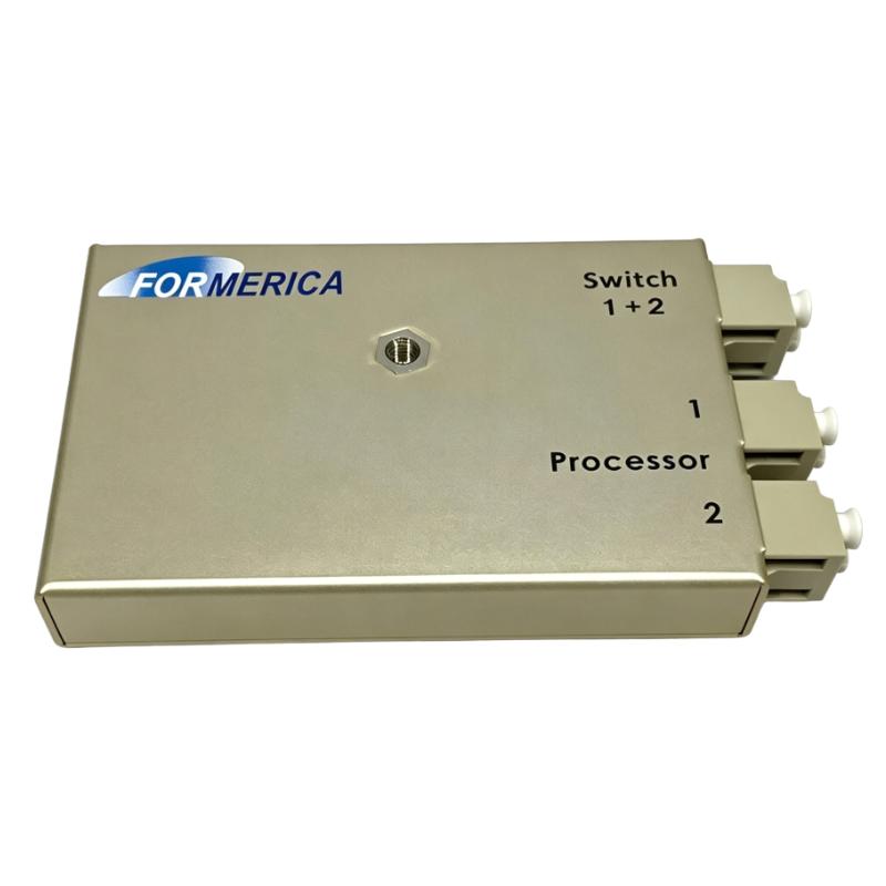
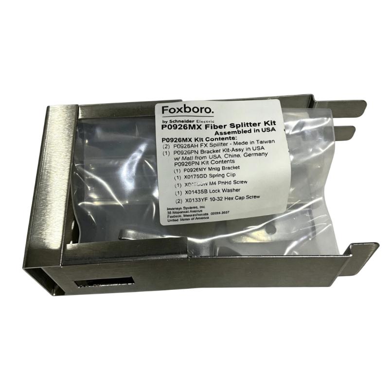
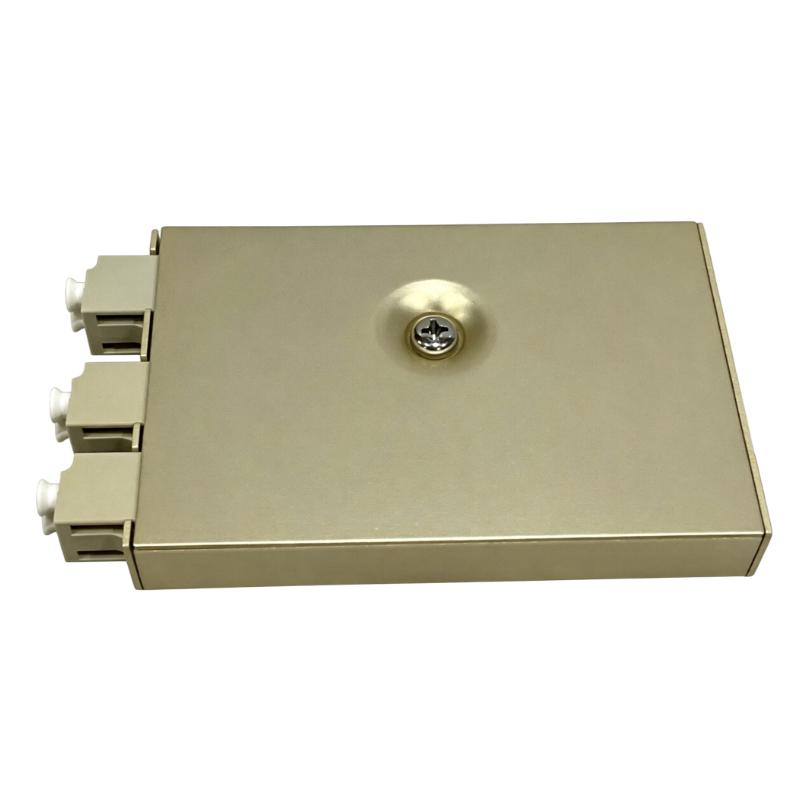
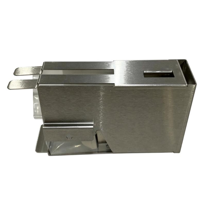
- Foxboro
- P0926MX
- Fiber Optic Coupler Kit
- USA
- 185 × 25 × 100 mm
- 0.45 kg
- Xiamen, China
- New & In Stock
- T/T, PayPal, Western Union
- 1 Year
- 1-3 Working Days
- DHL, UPS, TNT, FedEx and EMS.
- 24-Hour Service
- COO
- 61
Our advantage

Global Logistics
We have a 10-year logistics and express cooperation agreement, so our products can be shipped to any place in the world.

Brand new and original
Our products are imported in bulk from the place of origin. Because of the cooperative relationship, our products are all original and 100% new.

24-hour service
We provide 7*24 hours service to our customers. We will be there whenever you need us.

Price advantage
All our products are priced very favorably because we have our own warehouse and supply.
| Company Information | |||
| [email protected] | |||
| Mobile | +8615980777398 | ||
| +8615980777398 | |||
| 15980777398 |
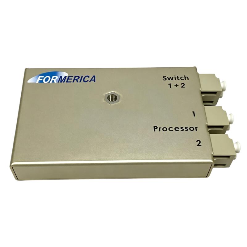
Product Overview
The Foxboro P0926MX Fiber Optic Coupler Kit is a fiber-optic communication accessory designed for compatible Foxboro industrial automation and distributed control system architectures. Its primary purpose is to provide a controlled optical connection between fiber-optic communication sections within a fieldbus or control-system network.
Fiber-optic communication is widely used in industrial control environments where electrical isolation, long-distance communication, and resistance to electromagnetic interference are important. A fiber-optic coupler or coupling assembly can provide a reliable connection between compatible optical communication components while maintaining the integrity of the communication path.
The supplied product information is:
- Manufacturer: Foxboro
- Model: P0926MX
- Product Type: Fiber Optic Coupler Kit
- Dimensions: 185 × 25 × 100 mm
- Weight: 0.45 kg
- Primary Function: Fiber-Optic Coupling
- Application: Industrial DCS / Fieldbus Communication
- System Role: Optical Communication Interconnection
The P0926MX should be installed only in a compatible Foxboro fiber-optic communication architecture. Before replacement, technicians should verify the optical interface, connector arrangement, network topology, and system-specific installation requirements.
Technical Specifications
| Parameter | Specification |
|---|---|
| Manufacturer | Foxboro |
| Model Number | P0926MX |
| Product Type | Fiber Optic Coupler Kit |
| Dimensions | 185 × 25 × 100 mm |
| Weight | 0.45 kg |
| Main Function | Fiber-Optic Coupling |
| Application | Industrial Automation / DCS |
| Communication Medium | Optical Fiber |
| Installation Role | Fiber Network Interconnection |
| Component Category | Communication Accessory |
| Maintenance Type | Installation / Replacement / Inspection |
The supplied dimensions are 185 × 25 × 100 mm, with a supplied weight of 0.45 kg.
Function and Working Principle
The P0926MX provides an optical coupling function within a compatible fiber-optic communication system.
A simplified arrangement can be represented as:
Control System
↓
Fiber-Optic Transceiver
↓
Fiber Cable
↓
P0926MX Coupler
↓
Fiber Cable
↓
Remote Communication Node
The coupler provides a controlled optical connection between compatible fiber sections.
Unlike an electrical copper connector, an optical coupling assembly does not rely on conventional electrical signal conduction through the communication path. Instead, optical signals are transmitted through the fiber.
A properly installed optical connection helps maintain:
- Low optical loss
- Reliable communication
- Electrical isolation
- Resistance to electromagnetic interference
- Stable data transmission
The actual optical characteristics depend on the fiber type, connector design, system architecture, cable condition, and installation quality.
Role in Foxboro Industrial Control Systems
Fiber-optic communication can be especially valuable in industrial environments containing:
- Variable-frequency drives
- Large motors
- High-voltage equipment
- Power switching equipment
- Welding equipment
- Long cable runs
- High electromagnetic interference
A fiber-optic communication path provides electrical isolation between connected sections.
The P0926MX can therefore serve as part of the communication infrastructure connecting compatible Foxboro control-system components.
A simplified network might be:
Main Control System
→ Optical Interface
→ Fiber Cable
→ P0926MX
→ Fiber Cable
→ Remote Fieldbus Section
The actual topology should always follow the specific control-system design.
Fiber-Optic Coupling Principle
Fiber-optic communication depends on transmitting light efficiently between optical interfaces.
A simplified optical path is:
Transmitter
→ Optical Fiber
→ Coupler
→ Optical Fiber
→ Receiver
The quality of the coupling connection directly influences optical signal strength.
Contamination, poor alignment, damaged fiber ends, excessive bending, or an improperly installed connector can increase optical attenuation.
When attenuation becomes excessive, the receiver may no longer have sufficient optical signal strength to reliably decode the communication data.
This can produce:
- Communication errors
- Intermittent network faults
- Link loss
- Increased communication retries
- Remote node dropouts
Industrial Applications
Distributed Control Systems
The P0926MX may be used in compatible Foxboro DCS communication architectures where optical communication is required between system sections.
Process Automation
Fiber communication can provide reliable data transmission in process plants where electrical noise is significant.
Power and Utility Applications
Optical communication is useful in environments containing high-energy electrical equipment.
Oil and Gas Facilities
Fiber-optic communication can provide electrical isolation between control-system sections located in different areas.
Chemical Processing
Fiber communication can help reduce susceptibility to electromagnetic interference in electrically noisy plant environments.
Remote I/O Networks
Optical communication can be useful when fieldbus or I/O equipment is located at a significant distance from the main control equipment.
Installation Guide
1. Verify the P0926MX
Before installation, confirm:
Foxboro P0926MX
Fiber Optic Coupler Kit
Check:
- Model number
- Physical condition
- Kit completeness
- Optical interface configuration
- Fiber type compatibility
- Connector arrangement
Do not install a component with damaged optical interfaces.
2. Review the Optical Network
Before removing an existing coupler, identify:
- Optical transmitter
- Optical receiver
- Fiber cables
- Intermediate coupling components
- Remote communication equipment
- Optical network direction
Document the existing arrangement before making changes.
3. Place the System in a Safe Maintenance State
Depending on the network architecture, disconnecting a fiber-optic communication path can interrupt communication with remote I/O or control-system components.
Before installation:
- Follow the approved maintenance procedure.
- Place affected control loops in a safe condition.
- Isolate the affected communication section as required.
- Prevent unintended equipment operation.
- Follow site electrical and control-system safety requirements.
4. Inspect the Fiber-Optic Cables
Before connecting the coupler, inspect the optical cables.
Look for:
- Damaged jacket
- Crushed sections
- Excessive bending
- Broken connector housing
- Contaminated connector end
- Loose strain relief
- Signs of mechanical stress
Fiber cables should not be sharply bent.
5. Inspect the Optical Connectors
Optical connector cleanliness is critical.
Inspect for:
- Dust
- Oil
- Fingerprints
- Moisture
- Scratches
- Damaged alignment features
Even a small amount of contamination can increase optical loss.
6. Clean the Optical Interfaces
Use an approved fiber-optic cleaning procedure.
Do not use improvised cleaning materials that may scratch or contaminate the optical surface.
Never touch the optical end face with bare fingers.
7. Install the P0926MX
Position the coupler kit according to the applicable system configuration.
Ensure that:
- Fiber connectors are correctly aligned.
- Connector keys match.
- Connectors are fully inserted.
- Retaining mechanisms are secured.
- Fiber cables are not sharply bent.
- Mechanical stress is not transferred to the optical connectors.
Do not force a fiber connector.
8. Maintain Correct Fiber Routing
Route fiber cables so that they are protected from:
- Crushing
- Excessive bending
- Pulling
- Vibration
- Hot surfaces
- Sharp edges
- Moving machinery
Good cable management is important for long-term optical reliability.
9. Verify the Coupler Installation
Check:
- P0926MX position
- Connector engagement
- Fiber routing
- Mechanical mounting
- Cable strain relief
- Optical interface cleanliness
10. Restore the System
Restore the affected communication system according to the approved commissioning procedure.
Commissioning Procedure
Step 1 — Visual Inspection
Confirm that the P0926MX is correctly installed.
Step 2 — Check Fiber Connections
Verify both sides of the optical connection.
Step 3 — Check Cable Routing
Ensure that the fiber is not excessively bent or mechanically stressed.
Step 4 — Restore Communication
Restore the affected network.
Step 5 — Monitor Link Status
Check for:
- Optical link alarms
- Communication errors
- Remote node dropouts
- Data transmission interruptions
Step 6 — Verify Remote Devices
Confirm that the connected fieldbus or remote control-system components communicate correctly.
Step 7 — Monitor for Intermittent Faults
Continue monitoring the network after startup.
Troubleshooting Guide
Problem 1: Fiber Communication Does Not Work
Possible causes:
- Incorrect fiber connection
- Dirty optical connector
- Damaged fiber
- Incorrect coupler installation
- Optical transmitter problem
- Optical receiver problem
- Network configuration issue
Recommended Procedure
- Verify fiber connections.
- Inspect connectors.
- Clean optical interfaces.
- Inspect the fiber cable.
- Verify P0926MX installation.
- Check optical link status.
- Check the remote communication equipment.
Problem 2: Intermittent Fiber Communication
Possible causes:
- Loose connector
- Contaminated optical interface
- Damaged fiber
- Excessive cable bending
- Mechanical vibration
- Poor connector engagement
- Marginal optical signal strength
Intermittent optical communication should be investigated carefully because a connection may work temporarily while still having excessive optical loss.
Problem 3: High Optical Loss
Possible causes include:
- Dirty connector
- Scratched optical surface
- Damaged fiber
- Excessive bending
- Incorrect coupling
- Connector alignment problem
The coupler should not be assumed to be defective until the fiber and optical interfaces have been inspected.
Problem 4: Remote I/O Drops Offline
If remote I/O devices intermittently disappear, possible causes include:
- Fiber communication interruption
- P0926MX connection problem
- Damaged optical cable
- Optical interface fault
- Remote node power problem
- Controller communication problem
Determine whether the problem affects one node or an entire optical segment.
Problem 5: Communication Works After Restart but Fails Later
Possible causes include:
- Marginal optical connection
- Thermal expansion
- Mechanical vibration
- Intermittent cable fault
- Connector contamination
- Optical signal degradation
A temporary recovery after restarting does not necessarily indicate that the underlying problem has been resolved.
Problem 6: Fiber Connector Cannot Be Properly Installed
Possible causes:
- Incorrect connector type
- Incorrect orientation
- Damaged connector
- Foreign material
- Mechanical deformation
- Incompatible fiber interface
Never force an optical connector into place.
Problem 7: New P0926MX Does Not Restore Communication
If replacing the coupler does not solve the problem, investigate:
- Fiber cable
- Optical transmitter
- Optical receiver
- Remote communication module
- Connector condition
- Power supply
- Network topology
- Controller configuration
The coupler is only one element of the complete optical communication path.
Fiber-Optic Fault Diagnosis
A systematic diagnostic path is:
Control Processor
↓
Optical Communication Interface
↓
Fiber Cable
↓
P0926MX Coupler
↓
Fiber Cable
↓
Remote Communication Interface
↓
Fieldbus / I/O Network
This sequence helps technicians isolate the fault systematically.
Optical Communication Maintenance
Fiber-optic systems require different maintenance practices from copper communication systems.
Important maintenance areas include:
Connector Cleanliness
Optical surfaces should be kept clean and protected from contamination.
Cable Bend Radius
Fiber should not be bent beyond its allowable radius.
Mechanical Protection
Fiber cables should be protected from crushing and pulling.
Connector Engagement
Connectors must be fully seated.
Environmental Protection
Optical equipment should be protected from excessive dust, moisture, vibration, and temperature.
Common Maintenance Mistakes
Touching Optical Connector Ends
Fingerprints and oils can contaminate optical surfaces and increase signal loss.
Bending Fiber Too Sharply
Excessive bending can increase attenuation or permanently damage the fiber.
Pulling on the Fiber Cable
Mechanical force should be applied to appropriate connector or cable-support structures rather than directly to the fiber.
Installing the Wrong Fiber Interface
Fiber systems are not universally interchangeable.
The fiber type, connector configuration, and optical characteristics must be compatible with the system.
Replacing the Coupler Without Inspecting the Cable
A damaged fiber cable can produce exactly the same communication symptoms as a defective coupler.
Preventive Maintenance
| Inspection Item | Recommended Check |
|---|---|
| P0926MX | Inspect physical condition |
| Optical Connectors | Check cleanliness |
| Fiber Cable | Inspect for damage |
| Cable Routing | Check bend radius |
| Connector Engagement | Verify secure connection |
| Strain Relief | Check mechanical support |
| Optical Link | Monitor stability |
| Communication Diagnostics | Check recurring faults |
| Environmental Conditions | Inspect dust/moisture/vibration |
| Maintenance Records | Document changes |
Replacement Procedure
Phase 1 — Preparation
- Confirm P0926MX part number.
- Verify the optical interface.
- Review the network topology.
- Prepare approved fiber-cleaning equipment.
- Place the system into a safe maintenance state.
Phase 2 — Removal
- Identify the existing coupler.
- Document the fiber connections.
- Disconnect the optical connectors carefully.
- Protect exposed optical interfaces.
Phase 3 — Installation
- Inspect the replacement P0926MX.
- Inspect and clean optical interfaces.
- Connect the fiber cables.
- Confirm proper engagement.
- Route the cables correctly.
- Secure the coupler mechanically.
Phase 4 — Commissioning
- Restore the system.
- Check optical link status.
- Verify communication.
- Check remote I/O.
- Monitor for intermittent errors.
Post-Maintenance Checklist
- Correct Foxboro P0926MX confirmed
- Dimensions verified: 185 × 25 × 100 mm
- Weight verified: 0.45 kg
- Fiber interface compatibility confirmed
- Existing optical topology documented
- System placed in safe maintenance state
- Existing coupler removed carefully
- Fiber connectors inspected
- Optical interfaces cleaned
- Fiber cables inspected
- P0926MX installed correctly
- Connectors fully seated
- Fiber bend radius maintained
- Cable strain relief checked
- System restored
- Optical communication verified
- Remote devices checked
- Communication stability monitored
- Final configuration documented
Key Advantages
- Designed for compatible Foxboro fiber-optic communication applications
- Provides controlled optical coupling
- Supports electrical isolation between communication sections
- Suitable for industrial DCS environments
- Helps maintain reliable fiber-optic communication
- Supplied dimensions of 185 × 25 × 100 mm
- Supplied weight of 0.45 kg
- Useful for fiber network installation and maintenance
- Supports communication infrastructure in electrically noisy environments
- Compact coupling solution for compatible optical networks
Technical FAQs
What is the Foxboro P0926MX?
The P0926MX is a Fiber Optic Coupler Kit used in compatible Foxboro industrial control-system communication architectures.
What is the main function of the P0926MX?
Its primary function is to provide an optical coupling connection between compatible sections of a fiber-optic communication network.
What are the dimensions of the P0926MX?
The supplied dimensions are 185 × 25 × 100 mm.
What is the weight?
The supplied weight is 0.45 kg.
Why is fiber-optic communication used in industrial automation?
Fiber provides electrical isolation and is highly resistant to electromagnetic interference, making it useful in electrically noisy industrial environments.
Can a dirty optical connector cause communication faults?
Yes. Contamination on optical interfaces can significantly increase optical loss and cause communication instability.
Why should the fiber cable not be sharply bent?
Excessive bending can increase optical attenuation and may permanently damage the fiber.
Why does the network work intermittently?
Possible causes include contaminated connectors, marginal optical signal strength, damaged fiber, poor connector engagement, vibration, or excessive bending.
Should the P0926MX be replaced when communication fails?
Not immediately. The fiber cable, connectors, optical interfaces, transmitter, receiver, power supply, and network configuration should also be checked.
What should be checked after installing the P0926MX?
Verify connector engagement, fiber cleanliness, cable routing, bend radius, optical link status, and communication with connected devices.
Can a fiber-optic coupler repair a damaged fiber cable?
No. A coupler provides an optical connection but does not repair damaged fiber.
Why is connector cleanliness important?
Even small particles or fingerprints can interfere with optical coupling and increase signal attenuation.
Conclusion
The Foxboro P0926MX Fiber Optic Coupler Kit is an optical communication accessory intended for compatible Foxboro industrial automation and DCS architectures. The supplied specifications identify dimensions of 185 × 25 × 100 mm and a weight of 0.45 kg.
Its primary role is to provide a controlled optical connection within a fiber-based communication path. By maintaining the optical connection between compatible fiber sections, the P0926MX can support reliable communication in industrial environments where electrical isolation and immunity to electromagnetic interference are important.
Correct installation requires careful attention to optical connector cleanliness, fiber compatibility, connector alignment, cable routing, and bend radius. Technicians should also inspect the entire communication path rather than assuming that a communication failure is caused by the coupler itself.
During troubleshooting, the recommended approach is to examine the optical connectors, fiber cable, P0926MX connection, communication interfaces, and remote devices systematically. This can prevent unnecessary replacement of functioning components.
With correct installation and preventive maintenance, the P0926MX can contribute to stable fiber-optic communication and reliable operation of compatible Foxboro control-system networks.