

ProductPRODUCT
Featured products
Contact Us
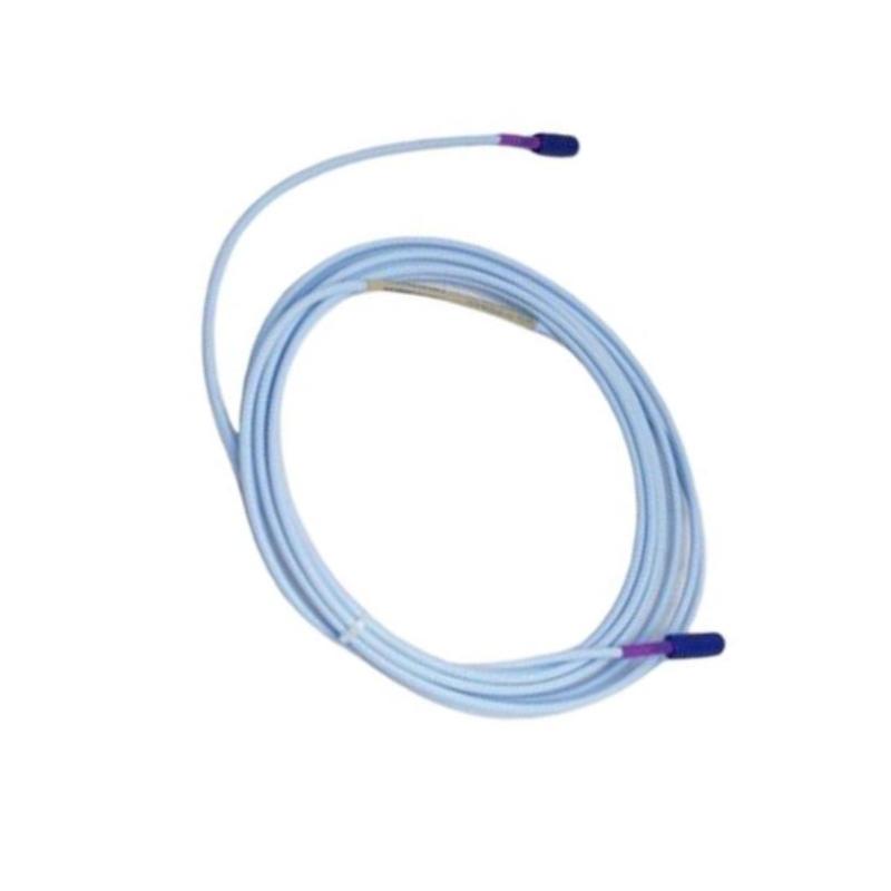
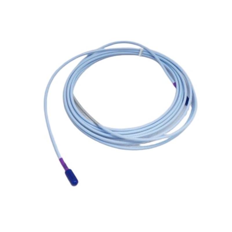
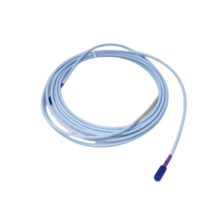
- Bently Nevada
- 330730-080-12-00
- 3300 XL 11mm Extension Cable
- USA
- 8.0 m
- 0.36kg
- Xiamen, China
- New & In Stock
- T/T, PayPal, Western Union
- 1 Year
- 1-3 Working Days
- DHL, UPS, TNT, FedEx and EMS.
- 24-Hour Service
- COO
- 16
Our advantage

Global Logistics
We have a 10-year logistics and express cooperation agreement, so our products can be shipped to any place in the world.

Brand new and original
Our products are imported in bulk from the place of origin. Because of the cooperative relationship, our products are all original and 100% new.

24-hour service
We provide 7*24 hours service to our customers. We will be there whenever you need us.

Price advantage
All our products are priced very favorably because we have our own warehouse and supply.
| Company Information | |||
| [email protected] | |||
| Mobile | +8615980777398 | ||
| +8615980777398 | |||
| 15980777398 |
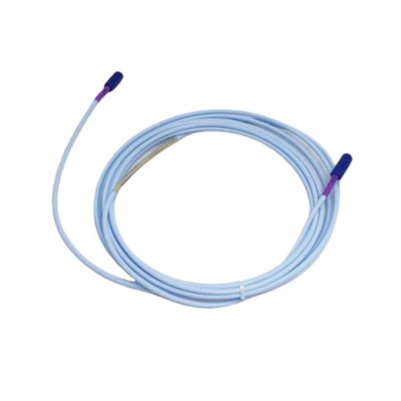
Bently Nevada 330730-080-12-00 Extension Cable — Complete Product Guide
1. Product Overview
The Bently Nevada 330730-080-12-00 is an extension cable for the 3300 XL 11 mm Proximity Transducer System. It connects a compatible proximity probe to a Proximitor Sensor, providing the electrical path required for shaft vibration and displacement measurements in industrial machinery.
This model uses an 8.0 m cable with the FluidLoc cable option and connector protectors. The connector protectors help protect the connection area during installation and handling, while the FluidLoc construction is designed to limit the migration of fluids through the cable interior.
The cable is a passive component rather than an independent sensor. Its job is to maintain the specified electrical connection between the probe and Proximitor Sensor so that the complete measurement system can operate as designed.
The final suffix 00 identifies the option for which no additional agency approval is specified. Where a project requires particular hazardous-area or regulatory approvals, the exact equipment configuration and documentation must be checked before installation.
2. Basic Product Information
| Parameter | Specification |
|---|---|
| Brand | Bently Nevada |
| Model number | 330730-080-12-00 |
| Product name | 3300 XL 11 mm Extension Cable |
| Product category | Industrial proximity-sensor extension cable |
| Product series | 3300 XL 11 mm Proximity Transducer System |
| Cable length code | 080 |
| Nominal cable length | 8.0 m |
| Equivalent length | Approximately 26.2 ft |
| Cable option | 12 |
| Cable construction | FluidLoc cable with connector protectors |
| Armor | Not fitted in the standard option 12 configuration |
| Approval option | 00 — no additional agency approval option |
| Main function | Connects a compatible proximity probe to its Proximitor Sensor |
| Measurement type | Eddy-current proximity measurement as part of a complete system |
| Typical application | Shaft vibration and relative displacement monitoring |
| Compatible equipment | Appropriate 3300 XL 11 mm probes and matching Proximitor Sensors |
| Cable material | 75 Ω triaxial cable with FEP insulation |
| Typical cable capacitance | 69.9 pF/m |
| Cable weight | Approximately 0.36 kg, commonly listed as the nominal cable weight |
| Cable dimensions | 8.0 m long; exact outside diameter depends on the specified cable section |
| Connector dimensions | Confirm against the applicable drawing |
| Shipping dimensions | Depend on packaging and accessories |
| Shipping weight | Depends on packaging and shipping method |
| Operating temperature | Approximately −51°C to +177°C for the cable family; verify the applicable specification |
| Power requirement | Passive cable; no independent power supply |
| Installation type | Pre-terminated cable assembly |
3. Detailed Technical Parameters
The 330730-080-12-00 is designed for use within a matched proximity measurement system. Its electrical properties, cable length, and connector configuration should be considered together with the probe and Proximitor Sensor.
| Technical parameter | Specification |
|---|---|
| Full model number | 330730-080-12-00 |
| Product family | 3300 XL 11 mm |
| Cable length | 8.0 m |
| Cable length in feet | 26.2 ft |
| Cable type | Extension cable |
| Cable option | 12 |
| Construction | FluidLoc cable with connector protectors |
| Armor configuration | Not fitted in the standard option 12 configuration |
| Cable impedance | 75 Ω |
| Cable design | Triaxial |
| Insulation material | Fluoroethylene propylene (FEP) |
| Typical cable capacitance | 69.9 pF/m |
| Capacitance in imperial units | 21.3 pF/ft |
| Center-conductor resistance | 2.0 ± 0.5 Ω for the specified 8 m assembly |
| Coaxial-conductor resistance | 0.6 ± 0.2 Ω for the specified 8 m assembly |
| Connector arrangement | Connector-protected configuration |
| Connector material | Gold-plated brass in the applicable ClickLoc configuration |
| Operating temperature | Approximately −51°C to +177°C; confirm the exact applicable rating |
| Storage temperature | Confirm the applicable cable specification |
| Agency approval suffix | 00 |
| Net cable weight | Approximately 0.36 kg |
| Shipping weight | Packaging-dependent; not fixed |
| Overall cable length | 8.0 m |
| Cable outside diameter | Confirm the applicable product drawing |
| Connector-protector dimensions | Confirm the applicable product drawing |
| Shipping package dimensions | Not fixed; depend on packaging |
| Electrical power consumption | None as an independent passive cable |
| Measurement function | Signal transmission between the compatible probe and Proximitor Sensor |
| Installation environment | Industrial installations within the cable’s specified environmental limits |
The electrical values listed above describe the cable assembly and its intended use. System output sensitivity and measurement range are characteristics of the complete probe-cable-Proximitor combination, not independent performance ratings of the extension cable.
4. Product Introduction
The Bently Nevada 330730-080-12-00 extension cable is a connecting component for industrial proximity measurement systems. It is designed to carry the electrical signal between a compatible 3300 XL 11 mm proximity probe and the associated Proximitor Sensor.
In a typical installation, the proximity probe is mounted near a conductive shaft. When the distance between the probe tip and the shaft changes, the probe’s electrical response changes accordingly. The Proximitor Sensor conditions this response and provides a signal that compatible machinery monitoring equipment can use to evaluate shaft vibration or relative displacement.
The extension cable is an essential part of this measurement loop. Its electrical characteristics, physical length, and connection quality affect the behavior of the overall system. Selecting the correct cable is therefore important when commissioning new equipment or replacing a damaged component.
The 8.0 m cable length offers flexibility when the probe and signal-conditioning equipment are installed some distance apart. The FluidLoc construction is intended to limit the migration of oil or other liquids through the cable interior, while the connector protectors help protect the connection area from accidental contact and handling damage.
This model is best understood as a precision connection component for a matched measurement system, rather than as a general-purpose industrial cable.
5. Product Applications
5.1 Steam turbine monitoring
Steam turbines operate under demanding mechanical conditions, making shaft vibration and displacement monitoring important parts of machinery maintenance.
The 330730-080-12-00 can connect a compatible proximity probe to its Proximitor Sensor in a suitable turbine monitoring arrangement. Stable electrical connections help monitoring equipment receive consistent measurement signals for trend analysis and fault investigation.
5.2 Gas turbines and generators
Gas turbines and generators may require continuous monitoring of shaft movement, particularly in applications where unexpected mechanical deterioration could result in expensive downtime.
The 8.0 m cable length can accommodate installations where the probe and Proximitor Sensor are separated by a significant distance. The cable should be routed within its specified temperature and environmental limits.
5.3 Centrifugal compressors
Centrifugal compressors commonly use shaft proximity measurements to help identify changes in rotor behavior and mechanical condition.
The extension cable carries the probe signal to the Proximitor Sensor. A correctly matched cable helps preserve the electrical characteristics of the measurement loop, while damaged connectors or incorrect replacement cables can contribute to unstable or misleading readings.
5.4 Industrial pumps
Large pumps may incorporate proximity sensors when their design and monitoring requirements call for shaft displacement measurement.
The FluidLoc cable option can be useful in machinery areas where oil or other fluids are present. However, the cable’s suitability for a particular chemical exposure or installation environment must be verified against the applicable material specification.
5.5 Industrial rotating equipment
The cable may be used in other suitable rotating machinery installations that employ the compatible 3300 XL 11 mm proximity transducer system.
Its purpose is to maintain the connection between the sensing and signal-conditioning components. The resulting measurements can support condition monitoring, maintenance planning, and investigation of abnormal machine behavior.
6. Product Advantages
6.1 FluidLoc cable construction
The FluidLoc design is intended to restrict fluid migration through the cable interior. This can be useful in machinery installations where lubricating oil or other liquids may come into contact with the cable.
It does not eliminate the need for correct installation, appropriate sealing at external interfaces, and regular inspection.
6.2 Connector protection
The option 12 configuration includes connector protectors. These help protect the connection area during handling, installation, and maintenance.
Connector protection is particularly useful in installations where technicians need to route cables through equipment spaces with limited clearance. The available space should still be checked before installation.
6.3 Defined electrical characteristics
The cable uses a 75 Ω triaxial design with FEP insulation and a specified capacitance. These characteristics are intended to match the requirements of the compatible proximity measurement system.
Using the correct cable configuration helps avoid problems that may arise from an unsuitable impedance, capacitance, or cable length.
6.4 Practical 8.0 m length
The 8.0 m length provides flexibility in locating the probe and Proximitor Sensor within the permitted system arrangement.
Selecting the appropriate cable length can also help keep cable routing organized and avoid unapproved splices or modifications.
6.5 Straightforward replacement
A pre-terminated cable assembly can simplify replacement work because it reduces the need for field termination.
Before fitting a replacement, technicians should verify the complete model number, connector condition, cable length, and compatibility with the installed probe and Proximitor Sensor.
6.6 Supports continuous condition monitoring
When used correctly in a complete measurement channel, the cable supports the transmission of data used for shaft vibration and displacement monitoring.
This can contribute to maintenance planning and machinery diagnostics, although monitoring performance depends on the entire system, its configuration, and the interpretation of collected data.
6.7 Established product family
The 3300 XL 11 mm system uses defined components intended to work together. Choosing a cable from the correct family makes it easier to check compatibility with the installed probe and Proximitor Sensor.
The full ordering code remains important because different suffixes can indicate differences in cable construction, connector protection, or approval options.
7. Brand and Product Series
| Item | Description |
|---|---|
| Brand | Bently Nevada |
| Product series | 3300 XL |
| System family | 3300 XL 11 mm Proximity Transducer System |
| Product type | Extension cable |
| Model | 330730-080-12-00 |
| Nominal cable length | 8.0 m |
| Cable construction | FluidLoc |
| Connector protection | Included |
| Main purpose | Connects a compatible probe to a Proximitor Sensor |
| Typical use | Industrial shaft vibration and displacement monitoring |
| Related components | 3300 XL 11 mm proximity probes, Proximitor Sensors, and compatible monitoring equipment |
The 3300 XL 11 mm family is intended for non-contact proximity measurements in suitable machinery applications. The probe detects movement relative to a target, the extension cable provides the electrical connection, and the Proximitor Sensor conditions the signal.
These components must be selected as a compatible system. A cable that has the correct physical length is not necessarily an appropriate replacement if its electrical characteristics or connector configuration differ from the required specification.
8. Five Related Models in the Same Series
The following models are related extension-cable configurations or nearby options within the same product family. They can help with comparison when selecting a cable for a new installation or a replacement.
| Model | Product type | Main parameters | Dimensions | Weight (kg) |
|---|---|---|---|---|
| 330730-080-12-05 | 3300 XL 11 mm extension cable | 8.0 m; FluidLoc cable; connector protectors; multiple-agency approval option | Cable length 8.0 m; connector dimensions require drawing | Approx. 0.36 kg |
| 330730-080-13-00 | 3300 XL 11 mm extension cable | 8.0 m; armored FluidLoc configuration with connector protectors; approval option 00 | Cable length 8.0 m; armor and connector dimensions require drawing | Configuration-dependent; verify |
| 330730-080-11-00 | 3300 XL 11 mm extension cable | 8.0 m; armored FluidLoc configuration; approval option 00 | Cable length 8.0 m; exact assembly dimensions require drawing | Configuration-dependent; verify |
| 330730-080-10-00 | 3300 XL 11 mm extension cable | 8.0 m; FluidLoc configuration; approval option 00; confirm exact option details | Cable length 8.0 m; connector dimensions require drawing | Configuration-dependent; verify |
| 330730-040-12-00 | 3300 XL 11 mm extension cable | 4.0 m; FluidLoc cable with connector protectors; approval option 00 | Cable length 4.0 m; connector dimensions require drawing | Approx. 0.18 kg as a length-based estimate; verify |
The 05 and 00 suffixes indicate different approval configurations. A model with a different cable option may also have different mechanical protection or connector details.
The weight for the 4.0 m model is only a length-based estimate using the approximate 45 g/m reference for a standard cable. Actual weight depends on the supplied configuration. Confirm all model codes and dimensions against the applicable product documentation before ordering.
9. Five Other Commonly Used Models from the Same Brand
These products are relevant to industrial machinery monitoring but perform different functions. They should not be treated as direct replacements for the 330730-080-12-00 extension cable.
| Model | Product name / type | Main parameters and function | Dimensions | Weight (kg) |
|---|---|---|---|---|
| 330101-00-08-10-02-00 | 3300 XL 8 mm proximity probe | Probe for a compatible proximity measurement system; exact probe configuration and thread details must be verified | Configuration-specific; consult drawing | Not confirmed |
| 330103-00-08-10-02-00 | 3300 XL 8 mm proximity probe | Proximity sensing component for suitable machinery installations | Configuration-specific; consult drawing | Not confirmed |
| 330104-00-08-10-02-00 | 3300 XL 8 mm proximity probe | Probe component for compatible proximity measurement applications | Configuration-specific; consult drawing | Not confirmed |
| 330180-50-00 | Proximitor Sensor | Signal-conditioning component used with a compatible proximity transducer system | Housing and mounting dimensions require the applicable drawing | Not confirmed |
| 3500/42M | Machinery monitoring module | Monitoring module for compatible machinery protection and condition-monitoring systems | Rack-mounted; exact dimensions depend on hardware configuration | Not confirmed |
The proximity probes, Proximitor Sensor, extension cable, and monitoring module have separate roles within a monitoring installation.
The probe detects changes in the gap between the sensor tip and the target. The extension cable connects the probe to the Proximitor Sensor, which conditions the measurement signal. A compatible monitoring module then processes the signal according to the installed system configuration.
Before choosing any of these models, confirm the installed equipment family, the complete order code, and the dimensions required for the mounting arrangement.
10. Installation and Maintenance Recommendations
Before installation
– Confirm the full model number and cable option.
– Check that the 8.0 m length is appropriate for the complete measurement system.
– Verify compatibility with the existing probe and Proximitor Sensor.
– Inspect the connectors, protector components, and cable jacket for visible damage.
– Check that the installation environment falls within the specified temperature and material limits.
During installation
– Route the cable to avoid sharp edges, crushing, excessive bending, and unnecessary mechanical stress.
– Leave sufficient clearance around the connector protectors.
– Keep the cable away from unsuitable heat sources and potential sources of mechanical damage.
– Avoid cutting, splicing, or modifying the cable unless the applicable instructions explicitly permit it.
– Follow the prescribed connector handling and installation procedure.
After installation
– Verify that both ends are connected securely.
– Perform the required continuity and system checks using the approved procedure.
– Confirm that the measurement channel produces plausible readings under the commissioning conditions.
– Record the installed model number and cable configuration for future maintenance.
Routine maintenance
Periodic inspections should focus on connector integrity, cable-jacket condition, routing supports, and signs of liquid exposure or physical damage.
If the measurement signal becomes intermittent or unstable, inspect the entire measurement loop. A fault may originate from the probe, cable, Proximitor Sensor, connectors, or associated monitoring equipment.
11. Dimensions and Weight Reference
| Physical parameter | Value |
|---|---|
| Nominal cable length | 8.0 m |
| Length in feet | Approximately 26.2 ft |
| Nominal cable weight | Approximately 0.36 kg |
| Cable outside diameter | Verify against the applicable cable drawing |
| Connector-protector dimensions | Verify against the applicable assembly drawing |
| Overall assembly length | 8.0 m nominal cable length, excluding any separately specified dimensional allowances |
| Shipping carton dimensions | Depend on packaging |
| Shipping weight | Depends on packaging and accessories |
| Product mounting dimensions | Not applicable to the cable itself; routing clearance must be checked |
The 0.36 kg figure refers to the nominal cable weight, not the packaged shipping weight. If the information is being used for purchasing, logistics, or a formal engineering specification, the delivered product’s dimensions and weight should be confirmed before the document is finalized.
12. Final Summary
The Bently Nevada 330730-080-12-00 is an 8.0 m extension cable for the 3300 XL 11 mm proximity transducer system. Its defining configuration is the FluidLoc cable with connector protectors and the 00 approval option.
Its principal role is to connect a compatible proximity probe to its Proximitor Sensor while preserving the electrical characteristics required by the complete measurement system. The 8.0 m length provides installation flexibility, the FluidLoc construction is intended to limit internal fluid migration, and the connector protectors provide additional protection around the connection area.
For selection and replacement, focus on the exact model code, cable length, connector configuration, system compatibility, and environmental requirements. The nominal cable weight is approximately 0.36 kg, while the exact cable diameter and connector dimensions should be confirmed against the applicable product drawing.