

ProductPRODUCT
Featured products



Contact Us
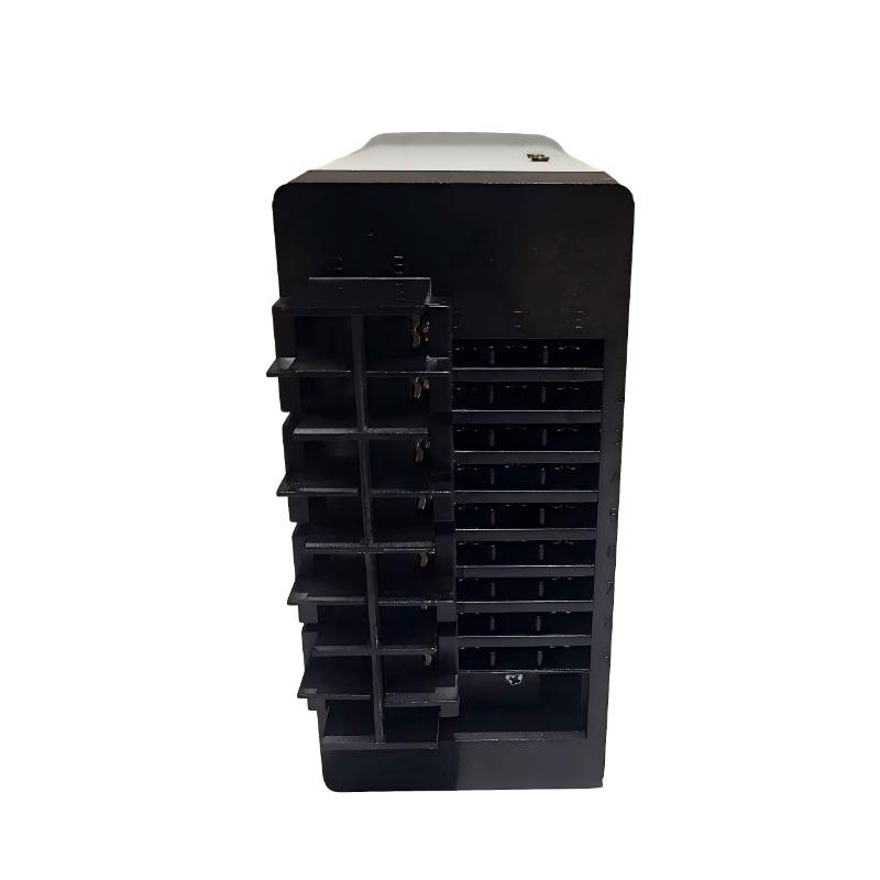
- Woodward
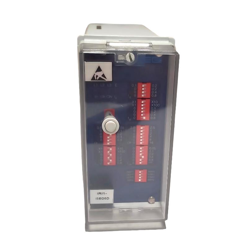
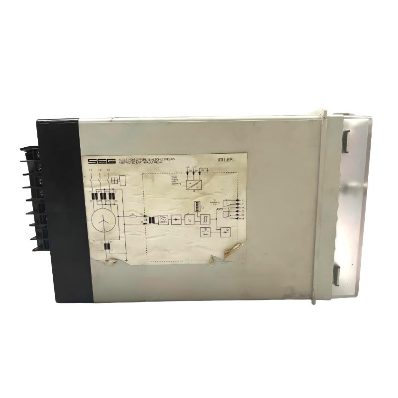
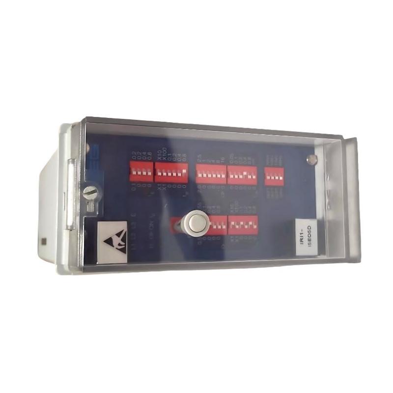
- IRI1-I5E05D
- Earth Fault Relay
- USA
- 260 × 72 × 138 mm
- 1.5 kg
- Xiamen, China
- New & In Stock
- T/T, PayPal, Western Union
- 1 Year
- 1-3 Working Days
- DHL, UPS, TNT, FedEx and EMS.
- 24-Hour Service
- COO
- 7
Our advantage

Global Logistics
We have a 10-year logistics and express cooperation agreement, so our products can be shipped to any place in the world.

Brand new and original
Our products are imported in bulk from the place of origin. Because of the cooperative relationship, our products are all original and 100% new.

24-hour service
We provide 7*24 hours service to our customers. We will be there whenever you need us.

Price advantage
All our products are priced very favorably because we have our own warehouse and supply.
| Company Information | |||
| [email protected] | |||
| Mobile | +8615980777398 | ||
| +8615980777398 | |||
| 15980777398 |
Product Overview
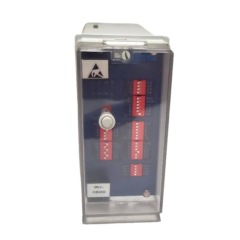
The Woodward IRI1-I5E05D is an earth fault protection relay used to detect abnormal residual or earth-fault current in electrical installations. It belongs to the IRI1 protection relay family, which monitors electrical current signals and initiates a trip response when configured protection conditions are met. In a switchgear or transformer protection circuit, the relay helps identify insulation faults that could otherwise damage equipment or create hazardous operating conditions.
Consider a transformer feeder in a distribution installation. Under normal conditions, the measured earth-current signal remains within the configured operating limits. If insulation deteriorates and current begins flowing to earth, the relay evaluates the measured signal against its protection settings. When the applicable threshold and timing conditions are satisfied, its output relay can initiate an alarm or trip through the associated protection circuit.
The IRI1-I5E05D configuration is associated with a 5 A rated current input and a withdrawable, flush-mounting housing arrangement. Its application depends on the current-transformer circuit, the selected earth-fault settings, the auxiliary supply, and the trip circuit connected to the relay. These details must be checked before commissioning or replacing an installed unit.
The relay is intended to operate as part of a wider electrical protection scheme. It does not replace correct current-transformer selection, circuit-breaker coordination, or the insulation and grounding measures required by the installation. Its effectiveness depends on properly configured protection settings and a functioning downstream trip circuit.
Technical Specifications
| Parameter | Specification |
|---|---|
| Manufacturer | Woodward |
| Model | IRI1-I5E05D |
| Product Family | IRI1 Protection Relay |
| Product Type | Earth Fault Relay |
| Protection Function | Earth-fault current detection and tripping |
| Rated Current Input | 5 A |
| Current Measurement | Current-transformer input |
| Protection Setting | Configurable according to the applicable relay settings |
| Trip Operation | Relay output for the configured protection function |
| Housing | Flush-mounting, withdrawable type |
| Size | 260 × 72 × 138 mm |
| Weight | 1.5 kg |
Product Features
- Earth-fault current monitoring: Detects abnormal earth-current conditions through the connected measurement circuit.
- 5 A rated current input: Matches installations using the corresponding current-transformer secondary circuit.
- Adjustable protection settings: Allows protection thresholds and operating delays to be configured for the application.
- Relay-based trip output: Supports the associated electrical trip circuit when the configured protection condition is reached.
- Front-panel indication: The IRI1 family uses status and fault indicators to assist with operational checks.
- Reset functionality: Supports fault-indication acknowledgement and reset according to the installed relay configuration.
- Withdrawable housing: Facilitates servicing in compatible flush-mounted installations.
- Application-specific coordination: Can be incorporated into a protection scheme with appropriately selected current transformers and switching equipment.
Working Principle
The IRI1-I5E05D operates by evaluating the earth-current signal supplied by the connected current-transformer circuit. The measured signal is conditioned and processed by the relay before being compared with the configured protection settings.
A typical protection arrangement follows this sequence:
Current Transformer → IRI1-I5E05D Earth Fault Relay → Trip Circuit → Circuit Breaker
During normal operation, the measured earth current remains below the configured operating threshold. If an earth fault develops, the resulting current signal changes. When the relay detects a condition that meets the configured pickup and timing criteria, it changes the state of its trip output. The connected protection circuit can then initiate the required switching action.
For example, if insulation damage develops in a transformer feeder, fault current may flow through an unintended path to earth. The relay evaluates the current signal and initiates a trip response when the configured protection conditions are met. Disconnecting the affected circuit can limit the duration of the fault and reduce the risk of additional equipment damage.
The pickup threshold and operating delay must be selected to suit the protected circuit. A setting that is too sensitive may cause unwanted trips during normal system conditions, while an excessively high threshold may reduce the ability to detect lower-level earth faults. Coordination with upstream and downstream protection devices is therefore essential.
The relay’s output does not interrupt the main power circuit by itself. The associated trip wiring, auxiliary supply, and circuit-breaker mechanism must all operate correctly for the protection sequence to be completed.
Role in an Electrical Protection Architecture
The IRI1-I5E05D forms part of the protection and tripping layer in an electrical distribution or transformer installation. Its task is to evaluate the measured earth-current signal and issue a trip command when the configured criteria are satisfied.
Protected Circuit → Current Transformer → IRI1-I5E05D → Trip Circuit → Circuit Breaker
| System Element | Function |
|---|---|
| Protected Feeder or Transformer | Electrical asset monitored for earth-fault conditions |
| Current Transformer | Supplies the current signal used by the protection relay |
| IRI1-I5E05D | Evaluates the earth-current signal against configured protection settings |
| Auxiliary Power Supply | Powers the relay according to its specified supply requirements |
| Trip Output Circuit | Transfers the relay’s trip command to the switching equipment |
| Circuit Breaker | Disconnects the protected circuit when the trip mechanism operates |
| Alarm Circuit | Provides fault notification where configured |
| Grounding System | Establishes the installation’s intended earth-current paths |
| Protection Coordination Scheme | Defines the relationship between this relay and other protective devices |
Correct operation depends on the entire chain, not only the relay itself. During commissioning, the current-transformer ratio, polarity, wiring, protection settings, and downstream trip circuit must be verified as part of the complete protection test.
Industrial Applications
| Application | Typical Use |
|---|---|
| Transformer Protection | Detecting earth faults in transformer-connected circuits |
| Medium-Voltage Switchgear | Monitoring earth-fault current in protected feeders |
| Low-Voltage Distribution | Providing earth-fault protection where the relay and measurement arrangement are suitable |
| Industrial Power Distribution | Monitoring electrical circuits supplying production equipment |
| Motor Feeder Protection | Detecting earth-fault conditions in appropriately configured motor circuits |
| Generator Auxiliary Circuits | Supporting earth-fault protection for compatible auxiliary circuits |
| Electrical Substations | Integrating earth-fault detection into a coordinated protection scheme |
| Industrial Utilities | Protecting selected distribution circuits against earth-fault conditions |
Application suitability depends on the system’s grounding method, current-transformer arrangement, fault-current characteristics, and required protection coordination. The relay settings must be selected for the actual installation rather than copied directly from another feeder or transformer.
Installation and Maintenance
- Verify the complete model number: Confirm that the relay is IRI1-I5E05D and that its current-input and housing configuration match the intended application.
- Check the current-transformer rating: Ensure that the connected secondary circuit is compatible with the relay’s 5 A rated current input.
- Review the protection scheme: Identify the protected circuit, grounding arrangement, upstream protection, and downstream trip device before commissioning.
- Inspect the mounting arrangement: Confirm that the flush-mounting opening, retaining hardware, and withdrawal mechanism are suitable for the relay housing.
- Isolate the relevant circuits: Follow approved electrical safety and lockout procedures before handling the relay or its associated wiring.
- Verify the auxiliary supply: Confirm the correct supply range and connection polarity, where applicable, using the documentation for the installed version.
- Check current-transformer wiring: Inspect terminal assignments, polarity, continuity, and connections against the protection circuit diagram.
- Review the pickup threshold: Set the earth-fault operating threshold according to the protected circuit and the required sensitivity.
- Configure the operating delay: Coordinate the relay’s response time with the other protective devices in the installation.
- Test the trip circuit: Verify that operation of the relay output produces the intended alarm or circuit-breaker trip response.
- Check indicators and reset behavior: Confirm that normal status, fault indication, and reset functions behave as expected after testing.
- Record the final settings: Document current-transformer details, pickup values, timing settings, trip connections, and test results for future maintenance.
Never open a current-transformer secondary circuit while primary current is flowing unless the circuit has been made safe using the appropriate shorting and isolation procedures. An open-circuited CT secondary can develop hazardous voltage. Protection testing should be performed by qualified personnel using approved procedures.
Compatible System Components
The IRI1-I5E05D must be integrated with a suitable current-transformer circuit, auxiliary supply, and downstream trip arrangement. The exact component selection depends on the protected equipment and the site’s protection coordination requirements.
| Component | Function |
|---|---|
| Compatible Current Transformer | Supplies the earth-current measurement signal |
| Auxiliary Power Supply | Powers the relay according to its rated supply requirements |
| Circuit Breaker | Disconnects the protected circuit following a trip command |
| Trip Coil Circuit | Converts the relay’s output into a switching action |
| Alarm Relay or Indication Circuit | Provides fault notification where configured |
| CT Secondary Wiring | Connects the current transformer to the relay input |
| Terminal Blocks | Organize current-transformer, supply, and trip wiring |
| Protection Test Equipment | Supports secondary-injection and functional testing |
| Electrical Enclosure | Houses the relay and associated protection equipment |
| Grounding System | Provides the intended earth-current path for the installation |
Recommended Related Models
The following models belong to or are associated with the Woodward IRI1 protection relay family. Their protection functions and order-code configurations differ, so confirm the required current input, measurement function, auxiliary supply, and housing before selecting an alternative.
| Model | Product Type | Typical Application |
|---|---|---|
| Woodward IRI1-I | Time Overcurrent Relay | Phase overcurrent protection |
| Woodward IRI1-IE | Time Overcurrent and Earth Current Relay | Combined phase-current and earth-fault protection |
| Woodward IRI1-E0 | Earth Current Relay | Earth-current protection |
| Woodward IRI1-ER | Highly Stabilized Earth Fault Relay | Earth-fault protection with stabilized measurement |
| Woodward IRI1-3ER | Three-Phase Highly Stabilized Earth Fault Relay | Three-phase earth-fault protection |
| Woodward IRI1-3 | Three-Phase Overcurrent Relay | Three-phase current protection |
Key Advantages
- Dedicated earth-fault current monitoring.
- 5 A rated current-input configuration.
- Adjustable protection pickup and operating delay.
- Relay output for integration with an external trip circuit.
- Withdrawable flush-mounting arrangement.
- Suitable for coordinated protection schemes when correctly configured.
Technical FAQs
What must match when connecting the IRI1-I5E05D to a current transformer?
The current-transformer secondary rating, ratio, polarity, wiring arrangement, and relay input rating must be compatible. For this configuration, verify the 5 A rated current input and confirm the earth-current measurement circuit against the protection design.
How should the earth-fault pickup threshold be selected?
The threshold should reflect the protected circuit’s normal residual-current conditions, grounding arrangement, expected fault current, and coordination requirements. The objective is to detect relevant earth faults without causing unnecessary trips during normal operation.
Why might the relay indicate an earth fault when the protected circuit appears normal?
Possible causes include incorrect current-transformer polarity, wiring errors, residual current under normal operating conditions, an unsuitable pickup setting, or a fault in the measurement circuit. Check the measured current and CT wiring before changing the protection settings.
Does the IRI1-I5E05D directly interrupt the main power circuit?
No. The relay provides a protection output that must be connected to an appropriate trip circuit. Successful interruption also depends on the auxiliary supply, trip wiring, and circuit-breaker mechanism operating correctly.