

ProductPRODUCT
Featured products
Contact Us
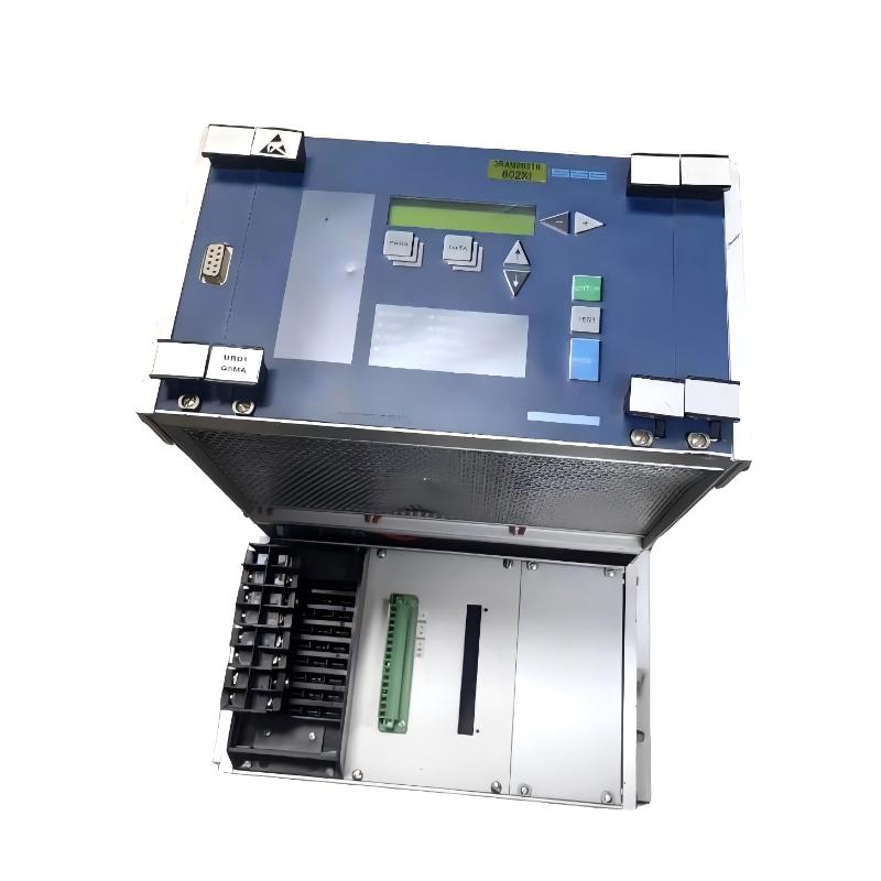
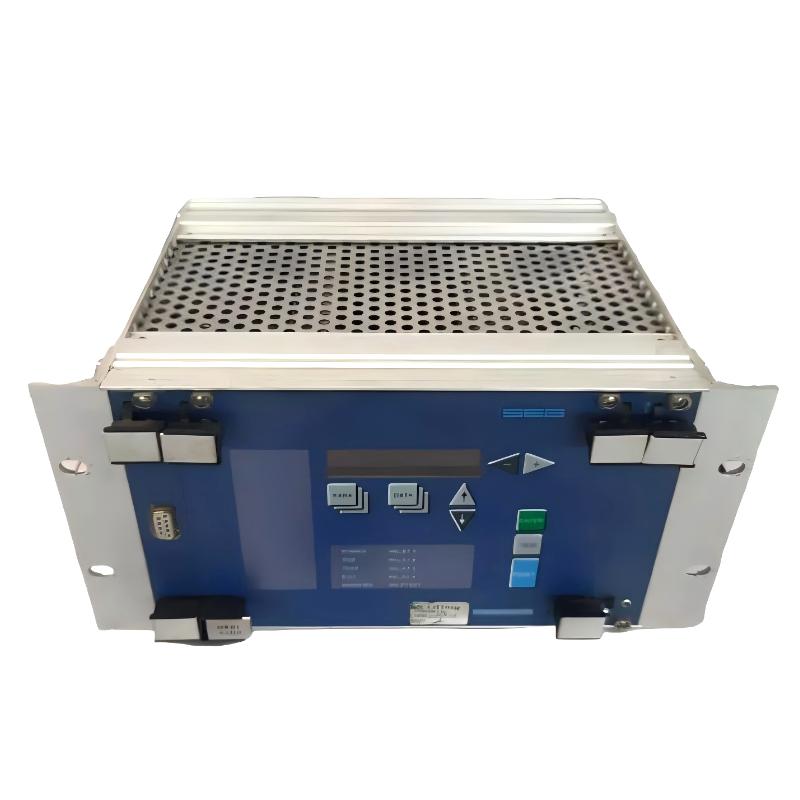
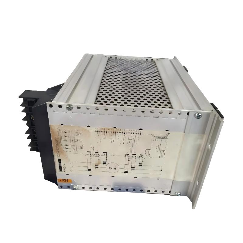
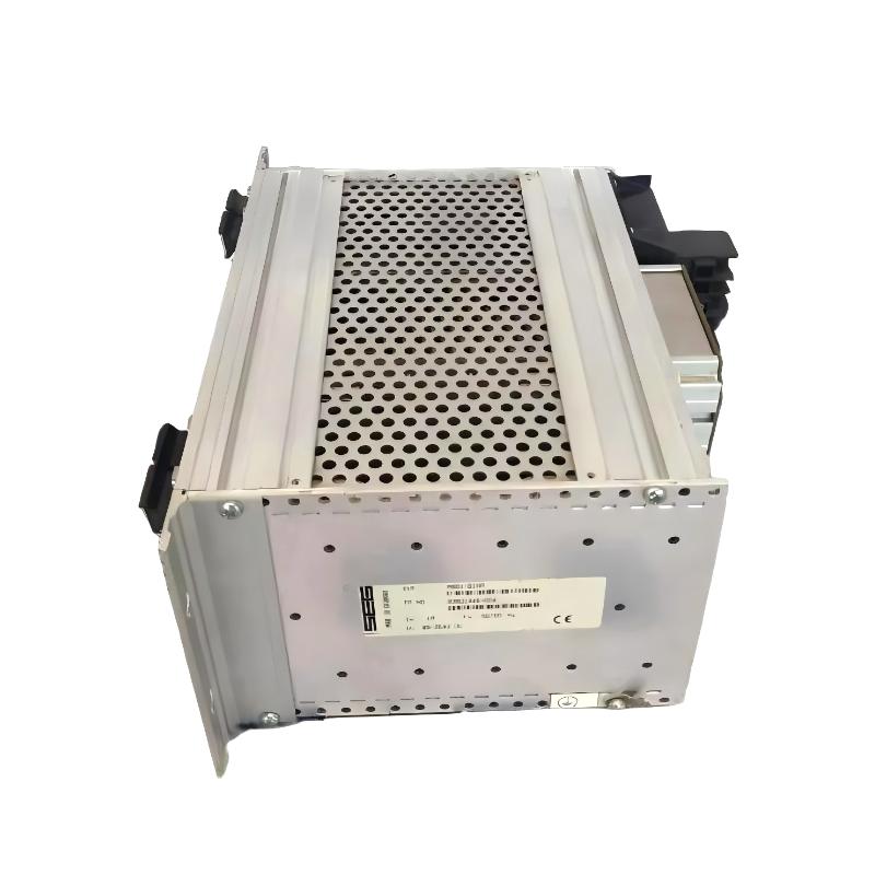
- Woodward
- MRD1T2HTL6M42
- Digital Speed Control Module
- USA
- 350 × 120 × 50 mm
- 1.55 kg
- Xiamen, China
- New & In Stock
- T/T, PayPal, Western Union
- 1 Year
- 1-3 Working Days
- DHL, UPS, TNT, FedEx and EMS.
- 24-Hour Service
- COO
- 7
Our advantage

Global Logistics
We have a 10-year logistics and express cooperation agreement, so our products can be shipped to any place in the world.

Brand new and original
Our products are imported in bulk from the place of origin. Because of the cooperative relationship, our products are all original and 100% new.

24-hour service
We provide 7*24 hours service to our customers. We will be there whenever you need us.

Price advantage
All our products are priced very favorably because we have our own warehouse and supply.
| Company Information | |||
| [email protected] | |||
| Mobile | +8615980777398 | ||
| +8615980777398 | |||
| 15980777398 |
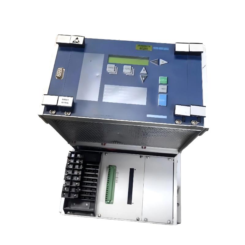
Product Overview
The Woodward MRD1T2HTL6M42 Digital Speed Control Module is an industrial control component intended for speed regulation in rotating machinery. In engine-driven equipment, maintaining the required rotational speed is essential for coordinating the prime mover with its mechanical load, operating sequence, and associated control equipment. The digital speed controller forms part of this regulation process by working with speed feedback and the actuator or fuel-control system.
In a typical engine-generator installation, the controller receives a speed-related signal and evaluates it against the commanded operating speed. When the measured speed deviates from the reference, the control system adjusts its output to influence the engine’s fuel delivery or governing mechanism. The resulting change in engine torque brings the rotational speed toward the requested operating point.
The MRD1T2HTL6M42 should be evaluated as part of the complete governing arrangement rather than as a standalone replacement board. Speed-sensor compatibility, actuator characteristics, control settings, and the interface with the engine or turbine system all affect its operation. A controller with a similar product description may still differ in its electrical connections or control configuration.
For maintenance and retrofit work, the full model designation is therefore an important part of component identification. Before installing a replacement, engineers should establish the original controller’s role, identify the connected speed sensor and actuator, and verify the required electrical and control interfaces against the existing installation.
Technical Specifications
| Parameter | Specification |
|---|---|
| Manufacturer | Woodward |
| Model | MRD1T2HTL6M42 |
| Product Type | Digital Speed Control Module |
| Product Function | Digital speed regulation |
| Application | Rotating machinery and engine speed-control systems |
| Control Method | Digital control |
| Speed Feedback | Depends on the installed system configuration |
| Actuator Interface | Must match the connected actuator and controller configuration |
| Size | 350 × 120 × 50 mm |
| Weight | 1.55 kg |
Product Features
- Digital speed regulation: Supports controlled adjustment of rotational speed within the capabilities of the configured governing system.
- Speed-feedback integration: Works as part of a control loop that uses speed-related input signals.
- Actuator coordination: Requires a compatible actuator or governing mechanism to translate controller output into changes in prime-mover operation.
- Application-specific configuration: Control behavior depends on the connected equipment and the settings established for the installation.
- Engine control integration: Can be evaluated for engine-driven equipment where its electrical and functional interfaces match the existing system.
- Maintenance-oriented identification: The complete model number helps distinguish the required module from other speed-control configurations.
Working Principle
The MRD1T2HTL6M42 is used within a speed-control loop in which the controller compares the measured rotational speed with the required reference. The controller processes the difference between these values and adjusts its output according to the configured control behavior.
A typical governing arrangement follows this sequence:
Speed Sensor → Digital Speed Controller → Actuator / Fuel-Control Mechanism → Engine or Prime Mover
Engine Speed Feedback → Controller → Speed Correction
When the engine is running below its commanded speed, the control system may increase the governing demand to raise engine torque. When the speed exceeds the reference, the controller can reduce the demand to bring the engine back toward the required operating point. The actual response depends on the actuator arrangement, control configuration, and operating limits of the prime mover.
For example, in an engine-generator installation, a sudden increase in electrical load can cause the engine speed to fall temporarily. The speed-control loop responds to the deviation and adjusts the governing mechanism to restore the required speed. The generator’s electrical output and the wider power-management system may impose additional operating requirements, particularly when the generator operates in parallel with other units.
The speed sensor and actuator must be compatible with the installed controller. An incorrect feedback signal can cause inaccurate speed measurement, while an incompatible actuator interface can prevent the control output from producing the expected response. Commissioning should therefore include checks of feedback polarity or signal characteristics where applicable, actuator movement, control direction, and the configured operating limits.
A digital speed controller is not, by itself, a complete overspeed protection system. Independent shutdown functions and other protective measures must be provided where required by the engine or turbine safety design.
Role in an Engine Speed-Control Architecture
The MRD1T2HTL6M42 belongs in the governing and speed-regulation part of a rotating-machinery control system. It operates in conjunction with speed feedback and the mechanism that adjusts the prime mover’s output.
Speed Reference → Digital Speed Controller → Actuator → Prime Mover
Speed Sensor → Digital Speed Controller → Feedback Correction
| System Element | Function |
|---|---|
| Speed Reference | Establishes the requested operating speed |
| Speed Sensor | Supplies a signal representing actual rotational speed |
| MRD1T2HTL6M42 | Processes speed-control information and determines the required correction |
| Actuator or Governing Mechanism | Converts the controller’s output into a change in prime-mover operation |
| Engine or Prime Mover | Produces mechanical power at the controlled speed |
| Generator, Where Applicable | Converts mechanical power into electrical output |
| Supervisory Controller | Coordinates operating commands and system-level functions where provided |
| Independent Overspeed Protection | Provides a separate protective response when required by the system design |
The controller’s actual position within the architecture depends on the original equipment design. Feedback wiring, actuator connections, speed references, and protective interlocks must be checked against the installed system before commissioning.
Industrial Applications
| Application | Typical Use |
|---|---|
| Engine-Driven Generator Sets | Regulating engine speed as electrical load changes |
| Industrial Engine Systems | Maintaining a commanded operating speed |
| Rotating Machinery | Supporting speed regulation where the controller is compatible |
| Mechanical Drive Systems | Coordinating prime-mover speed with the driven equipment |
| Power Generation Equipment | Forming part of the engine governing arrangement |
| Engine Retrofit Projects | Replacing a controller after verifying the original configuration |
| Industrial Utility Equipment | Supporting controlled operation of compatible engine-driven machinery |
| Maintenance and Overhaul | Restoring the speed-control function after module failure |
The suitability of this module depends on the specific prime mover, speed-sensing arrangement, actuator interface, and control requirements. Applications requiring load sharing, generator synchronization, or turbine-specific governing functions need additional verification to establish whether those functions are supported by the installed configuration.
Installation and Maintenance
- Verify the complete model number: Confirm that the replacement is MRD1T2HTL6M42 and compare the identification details with the installed module.
- Document the original wiring: Record the existing terminal connections and cable assignments before removing the controller.
- Isolate the equipment: Follow the site’s lockout procedures and ensure that the prime mover cannot start unexpectedly during maintenance.
- Inspect the mounting arrangement: Check the mounting hardware, enclosure, and connector locations before installing the module.
- Check the power supply: Confirm the required supply characteristics from the documentation for the exact controller configuration.
- Inspect the speed-sensor circuit: Verify sensor compatibility, wiring condition, signal integrity, and the expected feedback characteristics.
- Check the actuator interface: Confirm that the connected actuator or governing mechanism is compatible with the controller’s output.
- Review the control configuration: Verify the speed reference, operating limits, control direction, and other applicable settings.
- Inspect grounding and shielding: Check the installation’s grounding and signal-cable arrangements to reduce electrical interference where required.
- Test feedback and output behavior: Perform controlled checks to confirm that the controller receives the expected speed signal and produces the intended control response.
- Verify protective functions: Confirm the operation of required shutdowns, interlocks, and independent overspeed protection before returning the equipment to service.
- Record commissioning results: Document the module identification, control settings, sensor details, actuator connections, and test results for future maintenance.
Initial testing should be performed under controlled conditions with the driven equipment secured and the relevant protective functions available. Do not change governing settings indiscriminately to compensate for unstable speed; first investigate feedback quality, actuator behavior, mechanical loading, and the existing control configuration.
Compatible System Components
The MRD1T2HTL6M42 must be matched with the speed-feedback and governing equipment used by the target machine. The following component categories describe the surrounding control arrangement; they are not a confirmed list of model-specific compatible parts.
| Component | Function |
|---|---|
| Compatible Speed Sensor | Measures rotational speed and supplies feedback to the controller |
| Actuator or Fuel-Control Mechanism | Adjusts the prime mover’s output in response to the governing command |
| Control Power Supply | Supplies the controller according to its specified electrical requirements |
| Engine or Prime Mover | Provides the mechanical output being regulated |
| Generator, Where Applicable | Converts the engine’s mechanical output into electrical power |
| Speed Reference Circuit | Supplies the required operating-speed command |
| Electrical Connectors and Wiring | Carry power, feedback, and control signals |
| Supervisory Control System | Coordinates operating commands where the installation includes one |
| Independent Overspeed Protection | Provides separate protection against excessive rotational speed |
| Mounting Hardware | Secures the controller within the intended equipment enclosure |
Recommended Related Models
The following Woodward products are related to digital speed governing and engine control. They are alternatives to investigate by application, not confirmed direct replacements for the MRD1T2HTL6M42.
| Model | Product Type | Typical Application |
|---|---|---|
| Woodward 9905-131 | 723 Digital Speed Control | Digital speed regulation for compatible prime movers |
| Woodward 9905-292 | 721 Digital Speed Control | Speed control for reciprocating engines |
| Woodward 9905-1312 | 723PLUS Digital Speed Control | Engine governing and speed-control applications |
| Woodward 9907-018 | 2301A Speed Control | Speed regulation in compatible engine-driven systems |
| Woodward 9907-205 | ProAct Digital Speed Control System | Electronic governing with compatible ProAct actuators |
| Woodward 8440-2080 | easYgen Generator Set Controller | Generator-set control and coordination |
Key Advantages
- Supports digital regulation of rotational speed.
- Can be integrated into an engine governing loop when the interfaces are compatible.
- Works with speed feedback and an external governing mechanism.
- Suitable for evaluation in engine-driven machinery and power-generation systems.
- Allows replacement planning to focus on the complete control configuration rather than the product name alone.
Technical FAQs
What should be verified before replacing the MRD1T2HTL6M42?
Check the full model designation, supply requirements, speed-sensor interface, actuator connections, and installed control configuration. Also confirm whether the existing system relies on additional governing or supervisory functions that must be preserved during replacement.
What can cause unstable engine speed after installing a replacement controller?
Possible causes include an incompatible speed-feedback signal, incorrect control direction, actuator problems, unsuitable governing settings, or changes in the mechanical load. Verify the sensor and actuator operation before making adjustments to control parameters.
Can this module control a generator’s electrical frequency directly?
The controller regulates prime-mover speed, which influences generator frequency in a conventional synchronous generator system. Actual frequency control also depends on the generator, its electrical operating conditions, and any supervisory or load-sharing controls connected to the installation.
Does the digital speed controller replace an independent overspeed trip?
It should not be assumed to do so. Speed regulation and independent overspeed protection serve different purposes. The required protective shutdown arrangement must be established from the machine’s safety design and verified separately during commissioning.