

ProductPRODUCT
Featured products
Contact Us
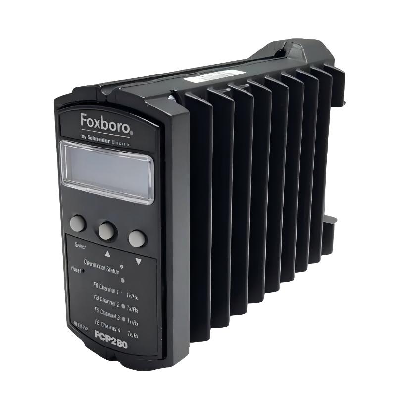
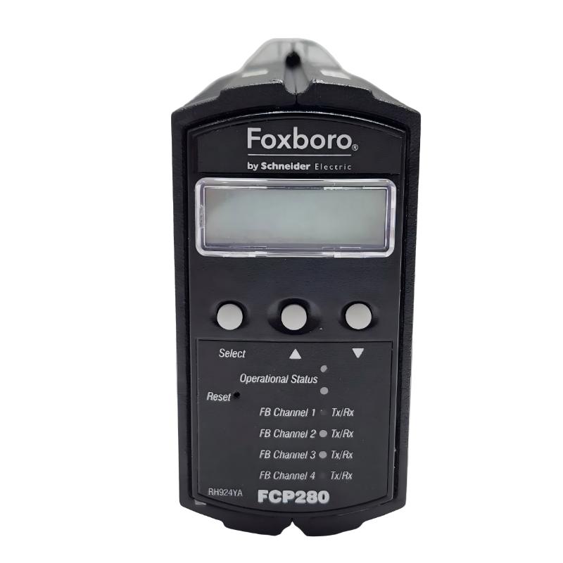
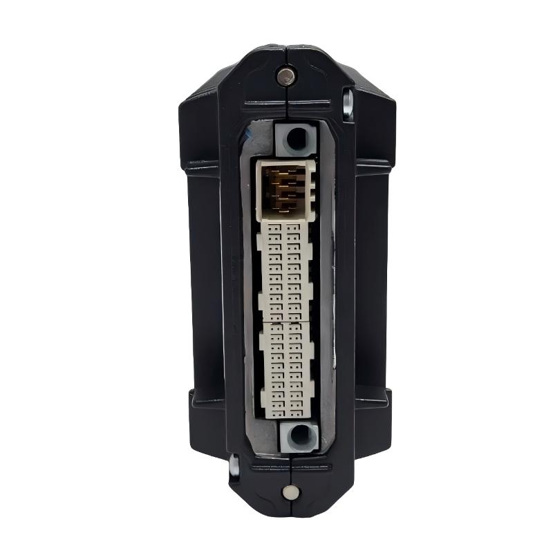
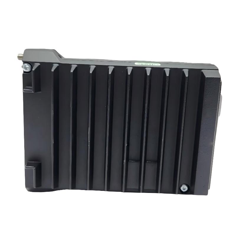
- Foxboro
- FCP280 RH924YL
- Horizontal Mount Base
- USA
- 150 x 35 x 110 mm
- 0.3 kg
- Xiamen, China
- New & In Stock
- T/T, PayPal, Western Union
- 1 Year
- 1-3 Working Days
- DHL, UPS, TNT, FedEx and EMS.
- 24-Hour Service
- COO
- 58
Our advantage

Global Logistics
We have a 10-year logistics and express cooperation agreement, so our products can be shipped to any place in the world.

Brand new and original
Our products are imported in bulk from the place of origin. Because of the cooperative relationship, our products are all original and 100% new.

24-hour service
We provide 7*24 hours service to our customers. We will be there whenever you need us.

Price advantage
All our products are priced very favorably because we have our own warehouse and supply.
| Company Information | |||
| [email protected] | |||
| Mobile | +8615980777398 | ||
| +8615980777398 | |||
| 15980777398 |
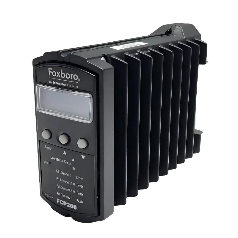
Product Overview
The Foxboro FCP280 RH924YL Horizontal Mount Baseplate is a dedicated mounting and interconnection base designed for the Foxboro FCP280 Field Control Processor. It provides the mechanical support and electrical interface required to install the FCP280 controller in a distributed control system.
The RH924YL is designed for horizontal mounting and is suitable for industrial control cabinets where the FCP280 needs to be installed on a horizontal DIN rail. The two-position design allows the base to support a single FCP280 controller or a two-controller configuration for applications requiring higher system availability.
The RH924YL is a passive infrastructure component rather than an active control module. It does not execute application logic or directly process field signals. Instead, it provides the physical connection between the FCP280, fieldbus infrastructure, network adapters, power connections, and associated DCS equipment.
The supplied product information specifies the following physical characteristics:
- Manufacturer: Foxboro
- Model: RH924YL
- Product Type: Horizontal Mount Base
- Dimensions: 150 × 35 × 110 mm
- Weight: 0.3 kg
- Associated Controller: FCP280
The RH924YL is particularly useful when cabinet layout, cable routing, service access, and controller orientation require a horizontal FCP280 installation.
Technical Specifications
| Parameter | Specification |
|---|---|
| Manufacturer | Foxboro |
| Model | RH924YL |
| Associated Controller | FCP280 |
| Product Type | Horizontal Mount Baseplate |
| Mounting Orientation | Horizontal |
| Mounting Method | DIN Rail |
| Controller Positions | 2 |
| Single Controller Installation | Supported |
| Redundant Controller Installation | Supported |
| Fieldbus Architecture | HDLC Fieldbus |
| Fieldbus Channels | 4 |
| Network Adapter Positions | 2 |
| Application | Foxboro DCS |
| Installation Environment | Industrial Control Cabinet |
| Dimensions | 150 × 35 × 110 mm |
| Weight | 0.3 kg |
| Primary Function | Controller Mounting and Electrical Interconnection |
Function and Working Principle
The RH924YL provides the physical infrastructure required to connect the FCP280 processor with the rest of the control system.
A simplified system structure can be represented as:
Field Instruments
↓
Fieldbus Modules
↓
Fieldbus Network
↓
RH924YL Base
↓
FCP280 Field Control Processor
↓
Network Interface
↓
DCS Control Network
↓
Operator and Engineering Stations
The FCP280 performs control processing, while the RH924YL provides the mounting and interconnection platform.
This distinction is important during troubleshooting. If an FCP280 reports communication problems, it is not always appropriate to replace the processor immediately. The baseplate, connectors, power wiring, fieldbus connections, and network interfaces should also be checked.
A damaged or poorly seated baseplate connection can produce symptoms that appear similar to a controller failure.
Two-Position FCP280 Configuration
One of the main characteristics of the RH924YL is its two-position architecture.
Single-Controller Configuration
A standard installation can use one FCP280:
Position 1 → FCP280
Position 2 → Unused
This arrangement is appropriate for applications where controller redundancy is not required.
Fault-Tolerant Configuration
A higher-availability installation can use two FCP280 processors:
Position 1 → Primary FCP280
Position 2 → Secondary FCP280
In this configuration, the controllers can be configured as a fault-tolerant pair.
Typical applications include:
- Continuous-process manufacturing
- Oil and gas
- Refining
- Chemical processing
- Power generation
- Water treatment
- Critical utility systems
The presence of two controller positions provides the physical foundation for redundancy, but the complete DCS configuration must also be correctly implemented.
Role in the Foxboro DCS
The RH924YL connects several parts of the FCP280 control architecture.
It can be associated with:
- FCP280 controllers
- Fieldbus connections
- Network adapters
- DC power
- Fieldbus Modules
- Control-network equipment
- Redundant controller configurations
The baseplate is therefore a critical part of the physical controller assembly.
A problem with the baseplate can potentially cause:
- Loss of controller communication
- Intermittent fieldbus communication
- Network communication faults
- Controller initialization problems
- Redundancy alarms
- Unexpected controller behavior
For this reason, the RH924YL should be inspected whenever a fault appears to involve the physical FCP280 installation.
Fieldbus Integration
The FCP280 architecture uses fieldbus communication to connect the processor with distributed I/O.
A typical signal path is:
Pressure Transmitter
→ Fieldbus I/O
→ Fieldbus Network
→ RH924YL
→ FCP280
→ Control Algorithm
→ Output I/O
→ Control Valve
This distributed architecture allows field I/O to be installed closer to process equipment.
The RH924YL provides the physical controller-side connection needed for this architecture.
When troubleshooting fieldbus problems, engineers should determine whether the failure affects:
- One field device
- One FBM
- One fieldbus segment
- Multiple fieldbus segments
- The entire controller
This fault pattern is useful for determining whether the problem is local to a field device or associated with common controller infrastructure.
Network Integration
The RH924YL provides positions for compatible FCP280 network adapters.
Depending on the system design, the FCP280 installation can use network connections based on:
- Copper Ethernet
- Fiber-optic communication
- Redundant communication paths
The network adapter provides the communication interface between the FCP280 and the wider DCS network.
When installing the network interface, verify:
- Correct adapter type.
- Correct mounting position.
- Secure mechanical connection.
- Correct network cable.
- Proper cable routing.
- Correct connection to the network infrastructure.
Installation Guide
1. Confirm the Product
Before installation, verify that the required component is:
Foxboro FCP280 RH924YL Horizontal Mount Base
Check the model number carefully.
The RH924YL should not be confused with other FCP280 mounting bases that use a different mounting orientation or fieldbus arrangement.
2. Inspect the Base
Perform a visual inspection before installation.
Check for:
- Cracked housing
- Broken mounting parts
- Damaged connectors
- Bent electrical contacts
- Corrosion
- Dust or contamination
- Mechanical deformation
- Signs of impact
Do not install a visibly damaged baseplate without first determining whether the damage affects mechanical or electrical integrity.
3. Prepare the DIN Rail
The RH924YL is intended for horizontal installation.
Before mounting:
- Confirm the DIN rail is correctly installed.
- Verify that the rail is mechanically stable.
- Check horizontal alignment.
- Ensure adequate cabinet clearance.
- Provide sufficient space for the FCP280.
- Leave enough room for fieldbus and network cables.
- Check that adjacent modules will not interfere with the controller.
Good cabinet planning is particularly important because network and fieldbus connectors require sufficient service access.
4. Install the Baseplate
Position the RH924YL on the DIN rail.
Engage the mounting mechanism and secure the baseplate.
After installation, verify:
- The base is level.
- The DIN-rail connection is secure.
- The baseplate does not move excessively.
- The controller position is accessible.
- Network connections are accessible.
- Fieldbus cables can be routed without excessive bending.
5. Verify Power Wiring
Before installing or energizing the controller, inspect the power connections.
Check:
- Supply voltage
- Polarity
- Wiring size
- Terminal tightness
- Protective devices
- Insulation
- Grounding arrangement
Do not energize the system until incorrect polarity and accidental short circuits have been ruled out.
6. Connect Fieldbus Wiring
Connect fieldbus cables to the appropriate connections.
Verify:
- Correct channel
- Correct wiring
- Cable shielding
- Termination
- Connector seating
- Cable routing
- Strain relief
Avoid excessive bending or pulling forces at the baseplate connectors.
7. Install the FCP280
Install the FCP280 processor into the designated position.
Before insertion:
- Inspect the FCP280 connector.
- Inspect the RH924YL connector.
- Check for foreign objects.
- Align the processor correctly.
- Insert it carefully.
- Secure the processor.
The processor should seat smoothly.
Never force the FCP280 into the baseplate.
If unusual resistance occurs, remove the processor and inspect the alignment and connector condition.
8. Install Network Adapters
Install the required network adapter or adapters.
Check:
- Correct model
- Correct mounting position
- Proper seating
- Connector condition
- Cable compatibility
For redundant systems, verify both network paths.
9. Connect Network Cables
Connect the appropriate network cables.
Inspect:
- Cable condition
- Connector condition
- Network port
- Network adapter
- Switch connection
- Link status
- Cable routing
Avoid routing communication cables directly alongside high-power conductors where unnecessary.
10. Final Installation Inspection
Before commissioning, perform a complete inspection.
| Item | Check |
|---|---|
| RH924YL | Correct model |
| DIN Rail | Secure and horizontal |
| FCP280 | Correctly seated |
| Power | Correct voltage |
| Polarity | Correct |
| Fieldbus | Correctly connected |
| Network Adapter | Correctly installed |
| Network | Correctly connected |
| Cabinet | Adequate clearance |
| Wiring | Secure |
| Redundancy | Correctly configured |
Commissioning Procedure
Step 1: Energize the System
Apply the required power to the control-system hardware.
Step 2: Check Controller Status
Verify that the FCP280 initializes correctly.
Step 3: Check Network Communication
Confirm that the controller can communicate with the DCS network.
Step 4: Check Fieldbus Communication
Verify that the expected fieldbus channels are available.
Step 5: Check I/O Modules
Confirm that the expected Fieldbus Modules are recognized.
Step 6: Verify Process Signals
Check representative:
- Pressure signals
- Temperature signals
- Flow signals
- Level signals
- Status inputs
Step 7: Check Outputs
Verify that output commands reach the appropriate field devices.
Step 8: Check Control Loops
Verify:
- Process variables
- Setpoints
- Outputs
- PID parameters
- Alarm limits
Step 9: Test Interlocks
Verify process permissives and equipment interlocks.
Step 10: Test Redundancy
If two FCP280 controllers are installed, confirm that the redundant controller arrangement operates correctly.
Troubleshooting Guide
Problem 1: FCP280 Does Not Start
Possible causes:
- No power
- Incorrect power polarity
- Loose wiring
- Poor processor seating
- Damaged connector
- Baseplate fault
- Controller fault
Troubleshooting Steps
- Verify the power supply.
- Measure voltage at the appropriate connection.
- Check polarity.
- Inspect wiring.
- Inspect the FCP280 connector.
- Inspect the RH924YL connector.
- Reseat the processor.
- Check controller diagnostic information.
If the processor remains inactive after power and mechanical connections are verified, investigate the controller itself.
Problem 2: FCP280 Is Not Recognized
If the controller is physically installed but the DCS cannot recognize it, check:
- Processor seating
- RH924YL connection
- Network adapter
- Network cable
- Network switch
- Controller configuration
- Power supply
A communication problem should not immediately be interpreted as a failed FCP280.
Problem 3: Multiple Fieldbus Modules Are Offline
If several FBMs disappear at the same time, investigate common infrastructure.
Possible causes include:
- Controller communication failure
- Fieldbus connection problem
- Baseplate connection problem
- Fieldbus power problem
- Incorrect termination
- Network configuration problem
The number and location of affected FBMs can provide useful diagnostic information.
Problem 4: One Fieldbus Channel Fails
If only one fieldbus channel is unavailable:
- Inspect the fieldbus cable.
- Check connectors.
- Verify termination.
- Inspect connected FBMs.
- Check channel configuration.
- Review controller diagnostics.
If other fieldbus channels remain operational, a complete controller failure is less likely.
Problem 5: Network Communication Is Lost
Possible causes include:
- Network adapter problem
- Damaged cable
- Loose connector
- Network switch problem
- Incorrect configuration
- Controller communication fault
- Power problem
Check the communication path systematically from the FCP280 outward.
Problem 6: Redundancy Is Not Working
For a two-FCP280 configuration, check:
- Both processors
- RH924YL baseplate
- Processor seating
- Power supply
- Network adapters
- Network paths
- Fieldbus connections
- Controller configuration
If only one processor reports an issue, compare its status with the other processor.
Problem 7: Intermittent Communication
Intermittent faults may be caused by:
- Loose connectors
- Mechanical vibration
- Cable movement
- Poor termination
- Power fluctuations
- Connector contamination
- Excessive temperature
- Electrical interference
Record when the problem occurs.
Determine whether it affects:
- One controller
- Both controllers
- One fieldbus
- Several fieldbuses
- One network path
- The entire DCS node
This can help isolate the fault.
Problem 8: Communication Fails After Cabinet Maintenance
If communication worked normally before maintenance but failed afterward, inspect the recently disturbed equipment first.
Check:
- FCP280 seating
- RH924YL connectors
- Network cables
- Fieldbus cables
- Power wiring
- Network adapters
- DIN-rail mounting
A partially seated module or loose communication cable can create a fault immediately after cabinet work.
Maintenance Recommendations
The RH924YL should be included in periodic control-system maintenance.
| Maintenance Area | Inspection |
|---|---|
| Baseplate | Check mechanical condition |
| DIN Rail | Check mounting stability |
| FCP280 | Check seating |
| Connectors | Inspect contacts |
| Power | Verify wiring |
| Fieldbus | Inspect cables |
| Network | Inspect connections |
| Cabinet | Check temperature |
| Ventilation | Check airflow |
| Wiring | Check mechanical stress |
| Grounding | Verify system grounding |
| Diagnostics | Review recurring faults |
The baseplate should also be inspected whenever:
- The FCP280 is replaced.
- A network adapter is replaced.
- Fieldbus wiring is modified.
- The cabinet is relocated.
- Repeated communication faults occur.
Industrial Applications
Oil and Gas
The FCP280 architecture can be used in applications such as:
- Compressor control
- Pump control
- Flow control
- Pressure control
- Gas processing
- Pipeline systems
Refining
Typical applications include:
- Distillation
- Process heating
- Pump systems
- Compressor systems
- Storage systems
- Utility control
Chemical Processing
The system can support:
- Temperature regulation
- Pressure control
- Flow control
- Level control
- Batch processes
- Equipment interlocks
Power Generation
Possible applications include:
- Cooling systems
- Water systems
- Auxiliary equipment
- Fuel systems
- Process utilities
Water Treatment
Applications may include:
- Pump stations
- Tank control
- Filtration
- Flow control
- Chemical dosing
- Treatment processes
Compatible System Components
| Component | Function |
|---|---|
| RH924YL | Horizontal FCP280 Baseplate |
| FCP280 | Field Control Processor |
| RH924YF | Vertical FCP280 Baseplate |
| RH100JX | Dual-Cable FCP280 Baseplate |
| Compatible Network Adapter | Control Network Communication |
| Fieldbus Adapter | Fieldbus Communication |
| Foxboro FBMs | Distributed Field I/O |
| Ethernet Equipment | Network Infrastructure |
| DC Power Supply | System Power |
Component compatibility should always be verified against the specific FCP280 system architecture before replacement.
RH924YL vs RH924YF
| Feature | RH924YL | RH924YF |
|---|---|---|
| Product Type | FCP280 Mount Base | FCP280 Mount Base |
| Mounting Orientation | Horizontal | Vertical |
| DIN Rail | Yes | Yes |
| FCP280 Positions | 2 | 2 |
| Single Controller | Supported | Supported |
| Redundant Controller | Supported | Supported |
| Application | FCP280 DCS | FCP280 DCS |
| Main Difference | Horizontal Cabinet Arrangement | Vertical Cabinet Arrangement |
| Supplied Dimensions | 150 × 35 × 110 mm | 150 × 35 × 110 mm |
| Supplied Weight | 0.3 kg | 0.35 kg |
The most important selection difference is the mounting orientation.
If a cabinet has a horizontal DIN-rail arrangement, RH924YL is the appropriate baseplate configuration. If the cabinet requires vertical mounting, RH924YF is the corresponding alternative.
RH924YL vs RH100JX
RH924YL and RH100JX should not automatically be considered interchangeable.
The RH924YL is intended as a standard FCP280 horizontal mounting base, while RH100JX is associated with a different fieldbus connection architecture.
Before replacing one with another, verify:
- Fieldbus architecture
- Cable arrangement
- Controller compatibility
- Mounting requirements
- Network configuration
- Redundancy requirements
- Cabinet layout
A mechanically compatible component is not necessarily electrically or architecturally equivalent.
Key Advantages
- Designed for FCP280 controller installation
- Horizontal DIN-rail mounting
- Two controller positions
- Supports single-controller operation
- Supports redundant controller configurations
- Provides structured controller interconnection
- Supports FCP280 fieldbus architecture
- Supports compatible network adapters
- Suitable for industrial DCS cabinets
- Compact physical design
- Simplifies controller installation
- Supports organized fieldbus wiring
- Suitable for continuous-process applications
- Dimensions of 150 × 35 × 110 mm
- Approximate weight of 0.3 kg
Technical FAQs
What is the Foxboro FCP280 RH924YL?
The RH924YL is a horizontal mount baseplate for the Foxboro FCP280 Field Control Processor.
Is RH924YL a CPU module?
No. RH924YL is a mounting and interconnection base. The FCP280 is the active controller.
How many FCP280 controllers can be installed?
The two-position architecture supports one FCP280 or two FCP280 processors in an appropriate fault-tolerant configuration.
What is the mounting orientation?
The RH924YL is designed for horizontal mounting.
What are the dimensions of RH924YL?
The supplied dimensions are:
150 × 35 × 110 mm
What is the weight?
The supplied weight is:
0.3 kg
Can RH924YL support redundant controllers?
Yes. The two-position design supports a redundant FCP280 arrangement when the complete control system is configured accordingly.
Does RH924YL process field signals?
No. Field signal processing is performed by the FCP280 and associated I/O modules.
What is the difference between RH924YL and RH924YF?
RH924YL is intended for horizontal mounting, while RH924YF is intended for vertical mounting.
Can RH924YL be used with a single FCP280?
Yes. One controller can be installed while the second position remains unused.
What should be checked if the FCP280 loses communication?
Check the:
- RH924YL connection
- FCP280 seating
- Power supply
- Network adapter
- Network cable
- Fieldbus connections
- Control-network configuration
Can a baseplate problem cause intermittent faults?
Yes. Poor mechanical or electrical contact can cause intermittent controller, fieldbus, or network communication problems.
What should be checked before replacing RH924YL?
Verify:
- Exact model
- Controller compatibility
- Horizontal mounting requirement
- Fieldbus architecture
- Network configuration
- Power arrangement
- Redundancy requirements
- Cabinet dimensions
Conclusion
The Foxboro FCP280 RH924YL Horizontal Mount Baseplate is an important hardware component for FCP280-based distributed control systems. It provides the mechanical mounting and electrical interconnection necessary to integrate the FCP280 controller into an industrial DCS cabinet.
Its horizontal DIN-rail mounting configuration makes it suitable for cabinets where the controller must be arranged horizontally. The two-position design also provides flexibility for single-controller installations and fault-tolerant controller configurations.
With supplied dimensions of 150 × 35 × 110 mm and a weight of approximately 0.3 kg, the RH924YL provides a compact mounting solution for FCP280 systems.
For installation, the most important considerations are correct DIN-rail mounting, secure FCP280 seating, proper power connections, fieldbus wiring, network connections, and adequate cabinet clearance. During troubleshooting, engineers should inspect the RH924YL whenever controller communication, fieldbus communication, network connectivity, or intermittent hardware faults occur.
The RH924YL should be selected according to the actual FCP280 system architecture rather than solely by physical dimensions. Correct mounting orientation, fieldbus arrangement, network requirements, and redundancy configuration should all be considered when installing or replacing the baseplate.