

ProductPRODUCT
Featured products
Contact Us
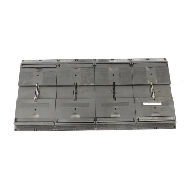
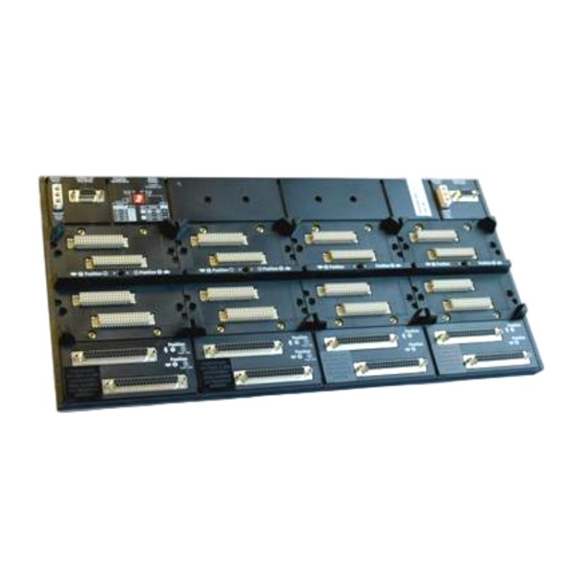
- Foxboro
- P0926JM
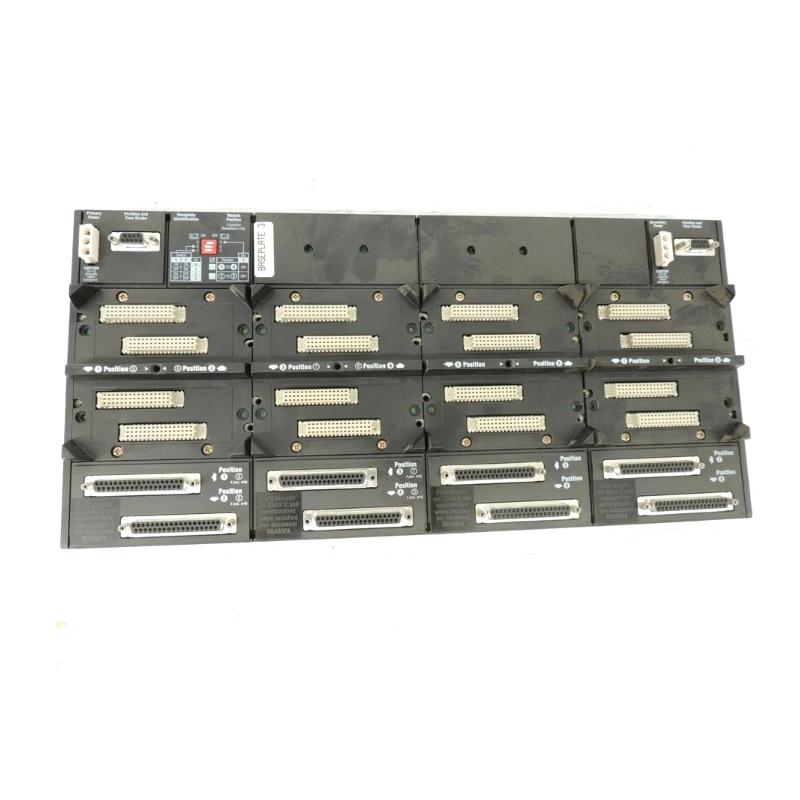
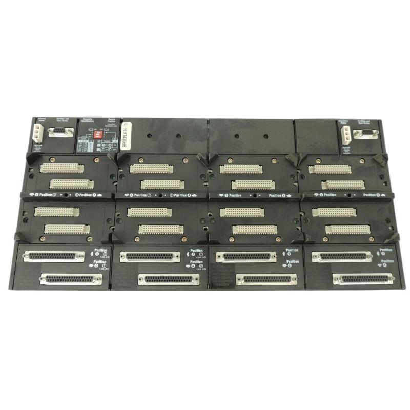
- DIN Rail Mount Modular Base Plate
- USA
- 453 x 27.1 x 216 mm
- 0.91 kg
- Xiamen, China
- New & In Stock
- T/T, PayPal, Western Union
- 1 Year
- 1-3 Working Days
- DHL, UPS, TNT, FedEx and EMS.
- 24-Hour Service
- COO
- 56
Our advantage

Global Logistics
We have a 10-year logistics and express cooperation agreement, so our products can be shipped to any place in the world.

Brand new and original
Our products are imported in bulk from the place of origin. Because of the cooperative relationship, our products are all original and 100% new.

24-hour service
We provide 7*24 hours service to our customers. We will be there whenever you need us.

Price advantage
All our products are priced very favorably because we have our own warehouse and supply.
| Company Information | |||
| [email protected] | |||
| Mobile | +8615980777398 | ||
| +8615980777398 | |||
| 15980777398 |
Product Overview
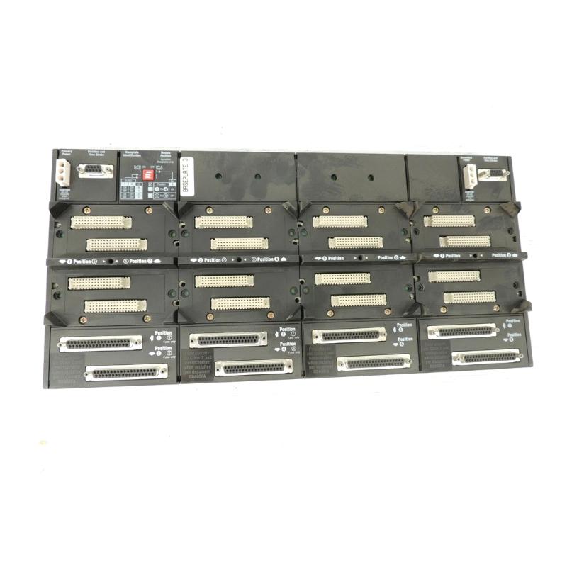
The Foxboro P0926JM DIN Rail Mount Modular Base Plate is a modular mounting and interconnection component designed for Foxboro distributed control system installations. It provides a structured platform for mounting compatible fieldbus and communication modules while establishing the electrical and communication connections required between the installed modules and the control-system infrastructure.
Unlike an active controller or I/O module, the P0926JM primarily serves as the mechanical and electrical foundation of a modular I/O assembly. Its DIN rail mounting design allows multiple compatible modules to be arranged in an organized cabinet installation.
The product information supplied for this model is:
- Manufacturer: Foxboro
- Model: P0926JM
- Product Type: DIN Rail Mount Modular Base Plate
- Mounting: DIN Rail
- Dimensions: 453 × 27.1 × 216 mm
- Weight: 0.91 kg
- Application: Industrial Automation and Distributed Control Systems
- Primary Function: Modular mounting and backplane interconnection
The P0926JM is particularly useful in systems where distributed I/O and communication modules need to be installed in a compact, serviceable cabinet arrangement.
Technical Specifications
| Parameter | Specification |
|---|---|
| Manufacturer | Foxboro |
| Model | P0926JM |
| Product Type | DIN Rail Mount Modular Base Plate |
| Mounting Method | DIN Rail |
| Application | Distributed Control System |
| Main Function | Module Mounting and Interconnection |
| Architecture | Modular I/O |
| Installation Environment | Industrial Control Cabinet |
| Module Interface | Compatible Modular Fieldbus / I/O Components |
| Dimensions | 453 × 27.1 × 216 mm |
| Weight | 0.91 kg |
| Maintenance | Modular Module Replacement |
| Communication Role | Provides Internal Module Interconnection |
Function and Working Principle
The P0926JM is designed to provide the physical foundation for a group of compatible Foxboro modules.
Its operation can be understood through three primary functions:
1. Mechanical Support
The baseplate holds compatible modules securely in their designated positions.
2. Electrical Interconnection
Internal connections allow installed modules to obtain the required power and electrical interfaces from the system architecture.
3. Communication Interconnection
The baseplate provides the internal connection path needed for communication between installed modules and the associated fieldbus or control-system infrastructure.
A simplified architecture is:
Control Processor
↓
Fieldbus Network
↓
P0926JM Modular Base Plate
↓
Fieldbus / I/O Modules
↓
Termination Assemblies
↓
Process Instruments
The P0926JM itself does not execute control logic. Instead, it provides the infrastructure that allows active modules to operate as an integrated system.
Role in Industrial Control Systems
A distributed control system frequently places I/O close to the process equipment instead of bringing every field signal back to a central cabinet.
The P0926JM supports this modular concept by allowing multiple compatible modules to be installed together.
A typical architecture is:
DCS Controller
↓
Control Network
↓
Fieldbus
↓
P0926JM
↓
I/O Modules
↓
Field Termination
↓
Sensors and Actuators
This arrangement can reduce point-to-point wiring and simplify cabinet organization.
It also makes maintenance easier because individual modules can be identified and serviced without rebuilding the complete I/O assembly.
Modular Baseplate Architecture
The P0926JM acts as a common platform for compatible modules.
Each installed module interfaces with the baseplate through its dedicated connector.
The resulting assembly can contain different types of I/O and communication modules depending on the application.
Typical signal categories may include:
- Analog inputs
- Analog outputs
- Digital inputs
- Digital outputs
- Process measurement signals
- Control outputs
- Communication interfaces
The actual module combination must be selected according to the control-system configuration.
DIN Rail Mounting
DIN rail installation provides a practical method of securing modular automation hardware inside industrial cabinets.
The P0926JM’s DIN rail mounting concept provides several benefits:
- Organized cabinet layout
- Efficient use of panel space
- Easy module access
- Modular expansion
- Simplified replacement
- Structured wiring
- Reduced installation complexity
Because the P0926JM is relatively large compared with compact single-module mounting components, the DIN rail must be firmly secured to the cabinet structure.
Mechanical stability is important because movement of the baseplate can eventually place stress on module connectors.
Installation Guide
1. Confirm the Model
Before installation, verify the product label:
Foxboro P0926JM
Confirm that the selected baseplate is appropriate for the intended Foxboro modular architecture.
Do not install a similar-looking baseplate simply because its dimensions or connector arrangement appear compatible.
2. Inspect the Baseplate
Before mounting, carefully inspect the P0926JM.
Check:
- Housing
- DIN rail mounting mechanism
- Module connectors
- Electrical contacts
- Mounting structure
- Connector alignment
- Mechanical locking components
Look for:
- Cracks
- Broken locking mechanisms
- Bent contacts
- Corrosion
- Dust
- Contamination
- Mechanical deformation
Any damaged connector can result in intermittent communication or module detection problems.
3. Prepare the DIN Rail
The DIN rail should be:
- Straight
- Securely fixed
- Properly aligned
- Free from excessive vibration
- Free from heavy contamination
Because the P0926JM is a relatively long modular baseplate, the supporting DIN rail should have sufficient mechanical rigidity.
The rail should not flex significantly when the baseplate and installed modules are mounted.
4. Install the Baseplate
Position the P0926JM against the DIN rail.
Engage the mounting mechanism carefully.
Verify:
- Correct orientation
- Full DIN rail engagement
- Secure locking
- Proper alignment
- Minimal mechanical movement
After installation, gently check the baseplate for excessive movement.
5. Connect System Power
Before applying power, inspect the system power connections.
Check:
- Supply voltage
- Power wiring
- Terminal connections
- Polarity
- Protective devices
- Grounding
If the architecture uses redundant power, inspect both power paths.
Incorrect power wiring can cause multiple modules to malfunction simultaneously.
6. Connect Fieldbus Wiring
Connect the fieldbus cable to the designated interface.
Check:
- Correct communication path
- Correct cable
- Connector condition
- Cable routing
- Shielding
- Termination
Communication wiring should be separated from high-power conductors wherever practical.
7. Install Compatible Modules
Install each compatible module onto the P0926JM.
For each module:
- Confirm the module type.
- Align the module connector.
- Carefully insert the module.
- Confirm complete seating.
- Secure the module.
- Verify its position.
Do not use excessive force.
If a module does not fit smoothly, stop and inspect the connector alignment.
8. Connect Field Termination
Connect field wiring through the appropriate termination components.
Depending on the installed modules, field signals may include:
- Temperature
- Pressure
- Flow
- Level
- Valve position
- Motor status
- Digital status signals
- Analog process signals
Each field connection should be checked against the approved system wiring documentation.
9. Organize the Cabinet Wiring
Keep cables organized around the P0926JM.
Separate:
Signal / Communication Wiring
from:
High-Power Wiring
Avoid routing communication and sensitive signal cables directly alongside:
- Motor power cables
- VFD output cables
- Large contactors
- Transformer wiring
- High-current conductors
Commissioning Procedure
Step 1 — Mechanical Inspection
Verify:
- DIN rail
- P0926JM mounting
- Module seating
- Connector condition
- Cable routing
Step 2 — Power Inspection
Confirm that the power supply and connections are correct.
Step 3 — Fieldbus Inspection
Verify fieldbus cable connections.
Step 4 — Energize the System
Apply system power according to the approved commissioning procedure.
Step 5 — Check Module Status
Inspect module indicators and controller diagnostics.
Step 6 — Verify Communication
Confirm that the control processor recognizes the installed modules.
Step 7 — Verify I/O
Check representative:
- Digital inputs
- Digital outputs
- Analog inputs
- Analog outputs
Step 8 — Verify Process Values
Compare field values with expected process conditions.
Step 9 — Verify Alarms
Check communication and module diagnostic alarms.
Step 10 — Perform Functional Testing
Verify representative control functions before placing the system into normal operation.
Troubleshooting Guide
Problem 1: Multiple Modules Are Not Detected
If several modules installed on the P0926JM disappear from the control system simultaneously, investigate common infrastructure.
Possible causes include:
- Baseplate power failure
- Fieldbus communication failure
- Baseplate connector problem
- Controller communication fault
- Incorrect system configuration
Recommended Procedure
- Check system power.
- Check baseplate connections.
- Check fieldbus wiring.
- Check controller diagnostics.
- Inspect module seating.
- Inspect the P0926JM connectors.
If several modules fail together, the baseplate or common communication path should be investigated before replacing individual modules.
Problem 2: One Module Is Not Recognized
If only one module is unavailable, check:
- Module seating
- Module connector
- Baseplate connector
- Module configuration
- Field wiring
- Module status indicators
If a known-good compatible module works correctly in the same position, the original module may be faulty.
Problem 3: Intermittent Communication
Intermittent communication may result from:
- Loose module connection
- Loose fieldbus cable
- Dirty connector
- Damaged cable
- Mechanical vibration
- Electrical interference
- Power instability
Start with physical inspection.
Check whether gently moving the cable or module changes the fault condition. Such behavior can indicate a mechanical connection problem.
Problem 4: Complete Fieldbus Communication Failure
Possible causes include:
- Incorrect fieldbus connection
- Damaged fieldbus cable
- Incorrect termination
- Baseplate fault
- Controller-side communication problem
- Power failure
Troubleshoot the complete path:
Controller → Fieldbus → P0926JM → Modules
Do not replace the baseplate before checking the communication cable and controller-side interface.
Problem 5: Modules Lose Power
If multiple modules lose power simultaneously, check the common power path.
Inspect:
- DC power supply
- Power terminals
- Protective devices
- Wiring
- Baseplate power interface
- Redundant power path
If all modules fail at the same time, a common power problem is more likely than simultaneous individual module failures.
Problem 6: Module Communication Drops During High-Power Equipment Operation
If communication errors appear when large motors, drives, or contactors operate, investigate electrical interference.
Check:
- Signal cable routing
- Fieldbus cable routing
- Shielding
- Grounding
- Cabinet bonding
- Distance from motor cables
- VFD wiring
Improved physical cable separation can sometimes resolve communication instability without replacing hardware.
Problem 7: New Module Does Not Work After Replacement
If a replacement module produces the same fault, investigate:
- P0926JM
- Fieldbus connection
- Power supply
- Module configuration
- Controller
- Termination assembly
This helps distinguish a module fault from an infrastructure fault.
Problem 8: Fault Appears After Cabinet Maintenance
If the system operated normally before maintenance, inspect equipment that was physically disturbed.
Pay particular attention to:
- DIN rail
- P0926JM
- Module connectors
- Fieldbus cables
- Power wiring
- Termination connections
A partially seated module or connector can cause an intermittent fault that resembles an electronic failure.
Maintenance Recommendations
A preventive maintenance program should include the P0926JM and all modules installed on it.
| Inspection Item | Recommended Check |
|---|---|
| DIN Rail | Check mechanical stability |
| P0926JM Housing | Inspect for damage |
| Mounting Mechanism | Verify secure locking |
| Module Connectors | Check for contamination |
| Power Wiring | Check connection integrity |
| Fieldbus Cable | Inspect condition |
| Module Seating | Verify correct installation |
| Termination | Check wiring |
| Cabinet Environment | Check temperature and contamination |
| Vibration | Check for excessive movement |
| Diagnostics | Review recurring communication faults |
Industrial Applications
Oil and Gas
The P0926JM can be part of distributed I/O systems used for:
- Pump control
- Compressor monitoring
- Pipeline systems
- Tank farms
- Gas processing
- Utility systems
Chemical Processing
Potential applications include:
- Reactor monitoring
- Pressure control
- Temperature measurement
- Flow monitoring
- Level measurement
- Valve control
- Batch processing
Refining
Distributed I/O architectures can be used around:
- Pumping systems
- Process utilities
- Tank systems
- Heating systems
- Cooling systems
- Material-handling equipment
Power Generation
Possible applications include:
- Cooling-water systems
- Auxiliary equipment
- Water treatment
- Fuel systems
- Plant utilities
- Balance-of-plant monitoring
Water and Wastewater
Potential applications include:
- Pump stations
- Filtration
- Chemical dosing
- Water treatment
- Reservoir monitoring
- Wastewater processing
System Component Compatibility
| Component Type | Typical Function |
|---|---|
| DCS Controller | Executes control strategy |
| P0926JM | Modular mounting and interconnection |
| Fieldbus Modules | Process I/O |
| Communication Modules | Network communication |
| Termination Assemblies | Field wiring interface |
| Fieldbus Cable | Controller-to-I/O communication |
| Power Supply | Supplies system power |
| DIN Rail | Mechanical support |
The actual compatible module configuration should be verified against the specific control-system design.
P0926JM vs P0926KH
Both products are modular baseplate components, but their physical dimensions and installation arrangements differ.
| Feature | P0926JM | P0926KH |
|---|---|---|
| Product Type | DIN Rail Mount Modular Base Plate | Vertical DIN Rail Mounting Modular Base Plate |
| Supplied Dimensions | 453 × 27.1 × 216 mm | 216 × 27.1 × 120.3 mm |
| Weight | 0.91 kg | 0.39 kg |
| Main Function | Modular mounting/interconnection | Modular mounting/interconnection |
| Installation | DIN rail | Vertical DIN rail |
| Typical Use | Larger modular assembly | More compact modular assembly |
The two models should not be considered automatically interchangeable.
P0926JM vs Active I/O Module
The P0926JM and an active I/O module perform completely different functions.
| Feature | P0926JM | I/O Module |
|---|---|---|
| Active Electronics | Primarily passive infrastructure | Active electronics |
| Control Logic | No | Depends on module |
| Field Signal Processing | No | Yes |
| Module Mounting | Yes | No |
| Backplane Interconnection | Yes | Uses backplane |
| DIN Rail Installation | Yes | Via compatible baseplate |
This distinction is important during troubleshooting.
If several I/O modules fail simultaneously, the baseplate and common infrastructure should be considered.
Key Advantages
- DIN rail mounting
- Modular architecture
- Provides structured module installation
- Supports organized cabinet construction
- Simplifies module replacement
- Provides internal module interconnection
- Reduces point-to-point internal wiring
- Suitable for distributed I/O systems
- Supports industrial DCS applications
- Facilitates systematic troubleshooting
- Supplied dimensions of 453 × 27.1 × 216 mm
- Supplied weight of 0.91 kg
Technical FAQs
What is the Foxboro P0926JM?
The Foxboro P0926JM is a DIN rail mount modular base plate used to provide mechanical mounting and internal electrical/communication interconnection for compatible Foxboro modules.
Is P0926JM an active controller?
No. The P0926JM is a modular baseplate rather than a process controller.
What is the main function of P0926JM?
Its main functions are module mounting, electrical interconnection, and support for the communication architecture of the installed modules.
How is P0926JM installed?
It is installed on a suitable DIN rail inside an industrial control cabinet.
What are the dimensions of P0926JM?
The supplied dimensions are:
453 × 27.1 × 216 mm
What is the weight of P0926JM?
The supplied weight is:
0.91 kg
Can multiple modules be installed on P0926JM?
The baseplate is designed as a modular platform, allowing compatible modules to be arranged within the available positions according to the system configuration.
Does P0926JM execute process logic?
No. Process-control functions are performed by the active controller and I/O/communication modules installed in the system.
What should I check if several modules fail simultaneously?
Start with common infrastructure:
- Power supply
- Baseplate power connections
- Fieldbus cable
- Controller communication
- Baseplate connectors
What should I check if only one module fails?
Inspect the module seating, connector, configuration, field wiring, and corresponding baseplate interface.
Can a loose module cause communication problems?
Yes. Poor connector engagement can result in intermittent or complete communication loss.
Can electrical interference affect modules installed on P0926JM?
Yes. Fieldbus and signal wiring can be affected by electromagnetic interference, especially when communication cables are routed close to high-power equipment.
Can vibration affect the P0926JM?
Yes. Excessive vibration can affect DIN rail mounting, module seating, and electrical connections.
Should the P0926JM be replaced when one module fails?
Not necessarily. The module, wiring, power supply, fieldbus, and baseplate interface should be checked before replacing the baseplate.
What is the difference between P0926JM and P0926KH?
Both are modular baseplate products, but they have different physical dimensions and mounting configurations. The P0926JM supplied here measures 453 × 27.1 × 216 mm and weighs 0.91 kg, while the P0926KH supplied specification is 216 × 27.1 × 120.3 mm and 0.39 kg.
Conclusion
The Foxboro P0926JM DIN Rail Mount Modular Base Plate provides the mechanical and electrical foundation for compatible modular control-system hardware. It does not function as an independent controller; instead, it enables multiple active modules to be installed in a structured DIN rail configuration while providing the required internal interconnection.
Its supplied dimensions of 453 × 27.1 × 216 mm and weight of 0.91 kg make it suitable for larger modular installations where multiple I/O or communication components must be organized inside an industrial control cabinet.
Correct installation requires a secure DIN rail, accurate baseplate alignment, clean connectors, properly seated modules, reliable power connections, and correctly routed fieldbus wiring. During commissioning, technicians should verify both the physical installation and the communication status of every connected module.
For troubleshooting, the most important principle is to distinguish between an individual module fault and a common baseplate or infrastructure fault. If several modules fail simultaneously, power, fieldbus communication, and the P0926JM should be investigated first. If only one module is affected, the individual module and its corresponding connection should receive greater attention.
With proper installation, inspection, and maintenance, the P0926JM can provide a stable modular foundation for distributed Foxboro control-system I/O installations.