

ProductPRODUCT
Featured products
Contact Us
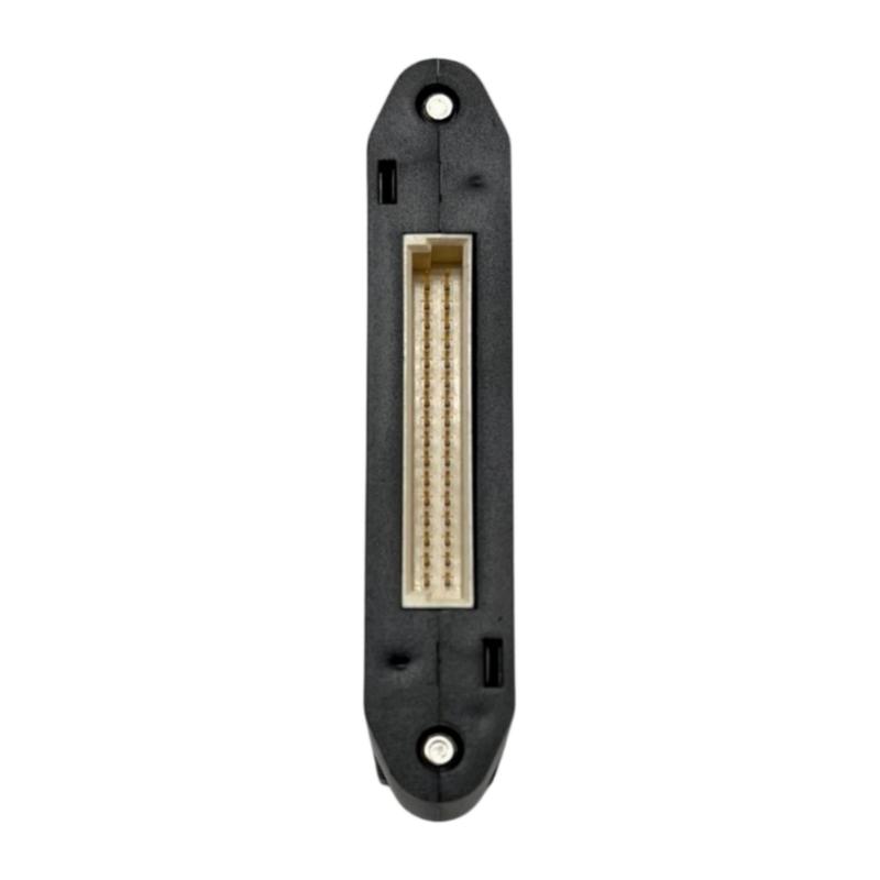
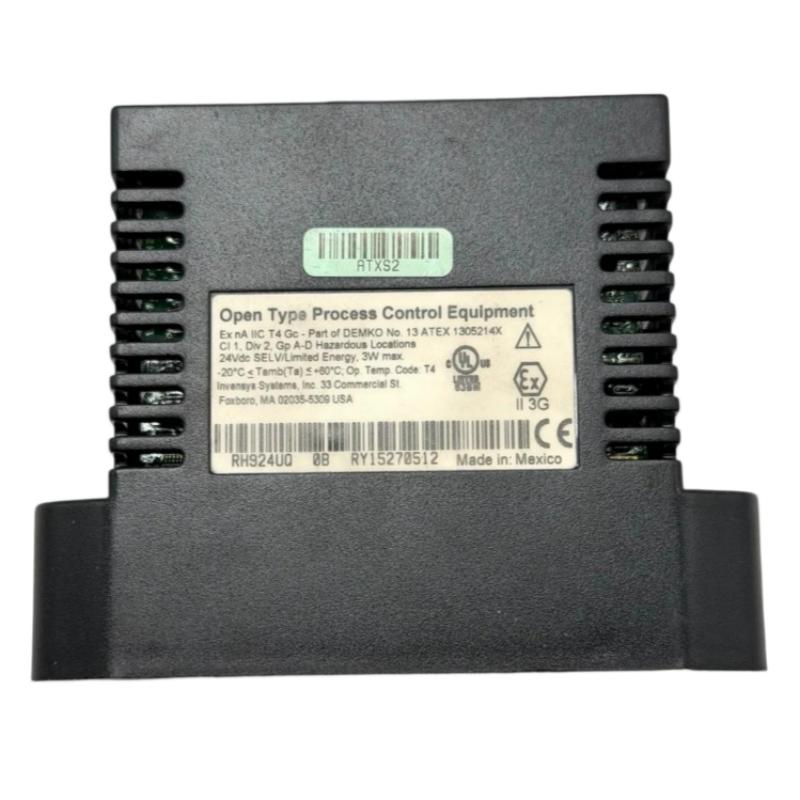
- Foxboro
- FCP280 RH924UQ
- Process Controller
- USA
- 130 x 25 x 100 mm
- 0.4 kg
- Xiamen, China
- New & In Stock
- T/T, PayPal, Western Union
- 1 Year
- 1-3 Working Days
- DHL, UPS, TNT, FedEx and EMS.
- 24-Hour Service
- COO
- 63
Our advantage

Global Logistics
We have a 10-year logistics and express cooperation agreement, so our products can be shipped to any place in the world.

Brand new and original
Our products are imported in bulk from the place of origin. Because of the cooperative relationship, our products are all original and 100% new.

24-hour service
We provide 7*24 hours service to our customers. We will be there whenever you need us.

Price advantage
All our products are priced very favorably because we have our own warehouse and supply.
| Company Information | |||
| [email protected] | |||
| Mobile | +8615980777398 | ||
| +8615980777398 | |||
| 15980777398 |
Product Overview
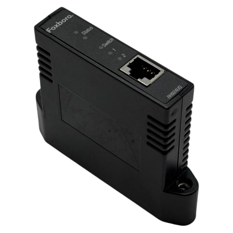
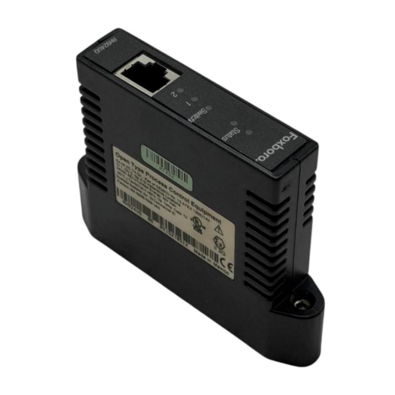
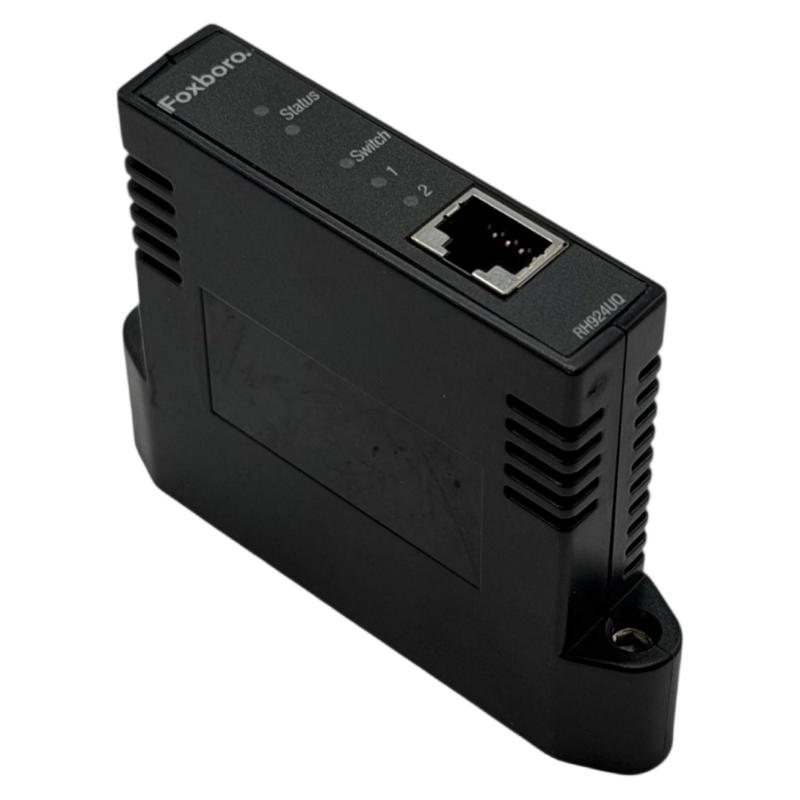
The Foxboro FCP280 RH924UQ is a network-interface component associated with the FCP280 distributed control system. In the FCP280 architecture, the RH924UQ provides the copper Ethernet communication interface used to connect the controller assembly to the DCS control network.
The FCP280 performs the actual process-control functions, while the RH924UQ provides the network communication path. This distinction is important when installing or troubleshooting the component because a network communication failure does not necessarily mean that the controller itself has failed.
The supplied product information is:
- Manufacturer: Foxboro
- Model: RH924UQ
- Associated System: FCP280
- Product Type: Process Controller / Copper Network Interface
- Dimensions: 130 × 25 × 100 mm
- Weight: 0.4 kg
- Application: Distributed Control System
- Communication: Copper Ethernet
The RH924UQ is designed to be installed as part of an FCP280 baseplate assembly. It provides a compact network connection for industrial process-control systems where reliable communication between the controller and control-network infrastructure is required.
Technical Specifications
| Parameter | Specification |
|---|---|
| Manufacturer | Foxboro |
| Model | RH924UQ |
| Associated Controller | FCP280 |
| Product Type | Process Controller / Network Interface |
| Network Interface | Copper Ethernet |
| Communication Medium | Twisted-Pair Ethernet |
| Installation | FCP280 Baseplate |
| Application | DCS Control Network |
| Network Architecture | Industrial Control Network |
| Redundant Network Application | Supported |
| Dimensions | 130 × 25 × 100 mm |
| Weight | 0.4 kg |
| Mounting Environment | Industrial Control Cabinet |
| Primary Function | Controller Network Communication |
Function and Working Principle
The RH924UQ provides the network communication interface for the FCP280 controller.
A simplified communication structure is:
Field Devices
↓
Fieldbus Modules
↓
FCP280
↓
RH924UQ
↓
Copper Ethernet Network
↓
Network Switch
↓
DCS Control Network
↓
Operator and Engineering Stations
The FCP280 processes control logic and process data. The RH924UQ provides the physical communication interface required for the controller to exchange information with the control network.
This separation between control processing and network interfacing is useful when performing fault diagnosis.
For example, if the FCP280 continues executing control functions but the DCS operator station cannot communicate with it, the RH924UQ, Ethernet cable, switch, network configuration, or another network component may be responsible.
Role in an FCP280 Control System
The FCP280 is normally positioned between distributed I/O and the higher-level DCS network.
A typical system can be represented as:
Sensors and Actuators
↓
Fieldbus Modules
↓
FCP280 Field Control Processor
↓
RH924UQ Network Interface
↓
Ethernet Control Network
↓
DCS Servers / Operator Stations
The RH924UQ therefore forms an important communication boundary between the controller assembly and the plant network.
It can be especially important in applications where the control network must remain continuously available during normal process operation.
Redundant Network Architecture
A redundant FCP280 installation can use separate network paths.
A simplified arrangement is:
FCP280
↙ ↘
RH924UQ A RH924UQ B
↓ ↓
Network A Network B
↓ ↓
Control Network
The purpose of this architecture is to reduce dependence on a single communication path.
A failure affecting one:
- Ethernet cable
- Network switch
- Network port
- Network adapter
- Communication path
does not necessarily have to interrupt the complete controller-network connection when the system has been correctly designed and commissioned for redundancy.
Copper Ethernet Communication
The RH924UQ uses a copper network interface.
Copper Ethernet offers several practical benefits for industrial automation:
- Easy installation
- Simple cable inspection
- Convenient replacement
- Familiar connector technology
- Straightforward network testing
- Easy integration with compatible Ethernet switches
- Lower installation complexity than some fiber installations
However, industrial Ethernet wiring should be routed carefully.
Avoid routing communication cables directly alongside:
- Variable-frequency-drive output cables
- Large motor cables
- High-current power cables
- Transformer wiring
- Contactor wiring
- High-power switching circuits
Where electrical noise is significant, proper shielding, grounding, cable separation, and cabinet layout become important.
Installation Guide
1. Confirm the Product
Before installation, verify that the component is:
Foxboro FCP280 RH924UQ
Confirm the model number on the product label.
Do not confuse RH924UQ with other FCP280-related components such as:
- RH924WA fiber-optic network adapter
- RH924YL horizontal base
- RH924YF vertical base
- Other FCP280 communication or mounting components
Correct identification is particularly important when replacing an existing network adapter.
2. Inspect the RH924UQ
Before installation, inspect the component carefully.
Check:
- Housing
- Network connector
- Mounting interface
- Electrical contacts
- Mechanical locking components
- Label
- Connector condition
Look for:
- Cracks
- Bent contacts
- Broken plastic
- Loose parts
- Corrosion
- Contamination
- Impact damage
If the network connector is damaged, do not install the component until the problem has been evaluated.
3. Prepare the Baseplate
The RH924UQ is mounted as part of the FCP280 baseplate assembly.
Before installation:
- Isolate power according to the plant maintenance procedure.
- Verify the correct baseplate.
- Inspect the mounting location.
- Check the electrical interface.
- Remove dust or contamination.
- Confirm that the baseplate is mechanically secure.
Never force a module into an incorrectly aligned position.
4. Install the RH924UQ
Position the RH924UQ correctly relative to the FCP280 baseplate.
Carefully engage the adapter with the corresponding interface.
Verify:
- Correct orientation
- Correct alignment
- Complete seating
- Secure mounting
- Proper connector engagement
If unusual resistance is encountered, stop installation and inspect the mating connectors.
Excessive force can damage both the adapter and the baseplate.
5. Verify the Power System
The RH924UQ is integrated into the FCP280 baseplate architecture.
Before applying power, check:
- DC power supply
- Baseplate wiring
- Power connections
- Protective devices
- Grounding
- Controller power status
A weak or unstable power supply can create symptoms that resemble communication hardware failure.
6. Prepare the Ethernet Cable
Inspect the Ethernet cable before connecting it.
Check:
- Cable jacket
- Connector
- Locking tab
- Contact condition
- Shielding
- Routing
Replace damaged cables rather than attempting to operate with unreliable connectors.
7. Connect the Network Cable
Connect the Ethernet cable to the RH924UQ.
Confirm:
- Connector fully inserted
- Locking tab engaged
- Correct communication port
- Cable has sufficient slack
- Cable is not under mechanical tension
Do not use the network cable as a means of supporting or pulling the adapter.
8. Connect the Network Switch
Connect the other end of the Ethernet cable to the assigned control-network switch.
Confirm:
- Correct switch
- Correct network port
- Correct network segment
- Correct cable
- Physical link status
For redundant installations, maintain strict separation between the designated network paths.
9. Inspect Cable Routing
After installation, verify that the Ethernet cable is not:
- Crushed
- Excessively bent
- Stretched
- Exposed to excessive heat
- Routed directly beside high-power cables
Good cable management improves long-term communication reliability.
Commissioning Procedure
Step 1: Apply Power
Energize the FCP280 system according to the approved commissioning procedure.
Step 2: Verify Controller Startup
Confirm that the FCP280 starts normally.
Step 3: Check RH924UQ
Verify that the network interface is physically secure and operating.
Step 4: Check Ethernet Link
Confirm the physical Ethernet connection between the RH924UQ and network switch.
Step 5: Check Network Communication
Verify that the controller communicates with the control network.
Step 6: Check DCS Visibility
Confirm that the controller is accessible from the appropriate engineering and operator environment.
Step 7: Check Field I/O
Verify representative input and output points.
Check:
- Analog inputs
- Digital inputs
- Analog outputs
- Digital outputs
- Fieldbus status
Step 8: Check Alarms
Verify controller and process alarms.
Step 9: Check Control Functions
Verify representative control loops and sequences.
Step 10: Verify Redundancy
If redundant network paths are installed, verify each path independently.
Troubleshooting Guide
Problem 1: FCP280 Cannot Communicate with the DCS
Possible causes include:
- RH924UQ incorrectly installed
- Loose Ethernet cable
- Damaged Ethernet cable
- Network-switch failure
- Incorrect switch port
- Controller power problem
- Baseplate problem
- Network configuration error
Troubleshooting Procedure
Start with the physical layer.
- Check controller power.
- Inspect RH924UQ seating.
- Check Ethernet connector.
- Test or replace the Ethernet cable.
- Check network-switch port status.
- Check network configuration.
- Review controller diagnostics.
- Compare with the redundant communication path if available.
Problem 2: Ethernet Link Does Not Establish
If the switch does not recognize the physical connection, inspect the communication path.
Check the Cable
Look for:
- Damaged jacket
- Broken locking tab
- Poor connector termination
- Loose connection
- Incorrect cable
Check RH924UQ
Verify that the adapter is correctly seated.
Check the Switch
Confirm that the selected port is operational and configured for the intended network.
Problem 3: Communication Is Intermittent
Intermittent communication is often more difficult to diagnose than a complete communication failure.
Possible causes include:
- Loose Ethernet connector
- Damaged cable
- Electromagnetic interference
- Poor cable routing
- Network-switch instability
- Power fluctuations
- Adapter hardware problem
- Mechanical vibration
Start with the physical connections.
If possible, replace the Ethernet cable temporarily with a known-good cable and observe whether the fault returns.
Problem 4: Communication Fails After Cabinet Maintenance
If communication worked normally before maintenance but fails immediately afterward, check all components that were disturbed.
Inspect:
- RH924UQ
- Baseplate
- Ethernet cable
- Network switch
- Power connections
A partially seated connector can create an apparent controller or network failure.
Problem 5: One Redundant Network Path Fails
If one network path operates normally while another is unavailable, compare the two paths.
Check the failed path in this order:
- RH924UQ installation
- Ethernet cable
- Switch port
- Network switch
- Network configuration
- Baseplate
- Controller diagnostics
The healthy path provides a useful reference for identifying differences.
Problem 6: Both Network Paths Fail
When both communication paths fail simultaneously, investigate common components first.
Possible causes include:
- FCP280 power failure
- Baseplate problem
- Controller fault
- Common network-switch failure
- Network configuration problem
- Common power problem
If two independent network cables appear to fail simultaneously, investigate the shared infrastructure before replacing both RH924UQ adapters.
Problem 7: Communication Errors Occur During Motor Startup
If communication becomes unstable when motors or drives start, investigate electromagnetic interference.
Check:
- Ethernet cable routing
- Shielding
- Grounding
- Cable separation
- Drive wiring
- Motor power cables
- Cabinet layout
The RH924UQ should not automatically be considered defective.
Problem 8: Replacing the RH924UQ Does Not Fix the Fault
If a replacement RH924UQ behaves exactly like the original, investigate:
- Ethernet cable
- Network switch
- Network port
- Baseplate
- FCP280
- Power supply
- Network configuration
This usually indicates that the fault may exist elsewhere in the communication chain.
Maintenance Recommendations
Regular inspection should include both the RH924UQ and its surrounding network infrastructure.
| Inspection Item | Recommended Check |
|---|---|
| RH924UQ Housing | Check physical condition |
| Mounting | Verify secure installation |
| Connector | Check for damage |
| Ethernet Cable | Inspect cable and connector |
| Network Switch | Check port status |
| Baseplate | Check mechanical/electrical connection |
| Power | Check stability |
| Network | Verify communication |
| Cabinet | Check temperature and contamination |
| Diagnostics | Review recurring faults |
| Redundancy | Verify alternate communication path |
Industrial Applications
Oil and Gas
The FCP280/RH924UQ architecture can be used in process-control environments involving:
- Pump systems
- Compressor systems
- Gas processing
- Pressure control
- Flow control
- Utility systems
- Pipeline facilities
Chemical Processing
Potential applications include:
- Reactor control
- Temperature regulation
- Pressure control
- Flow control
- Level control
- Batch processing
- Utility management
Refining
Typical process-control applications can include:
- Pumping systems
- Tank farms
- Process utilities
- Heating systems
- Distillation support systems
- Material-handling systems
Power Generation
The controller architecture can support:
- Cooling systems
- Water systems
- Fuel systems
- Auxiliary equipment
- Utility systems
- Balance-of-plant control
Water and Wastewater
Potential applications include:
- Pump stations
- Filtration
- Water treatment
- Chemical dosing
- Reservoir control
- Wastewater processing
Compatible System Components
| Component | Function |
|---|---|
| FCP280 | Field Control Processor |
| RH924UQ | Copper Network Interface |
| RH924WA | Fiber-Optic Network Interface |
| RH924YL | Horizontal FCP280 Base |
| RH924YF | Vertical FCP280 Base |
| Fieldbus Modules | Distributed Process I/O |
| Ethernet Switch | Control Network Communication |
| Ethernet Cable | Copper Network Connection |
| DC Power Supply | Controller System Power |
Compatibility should always be evaluated according to the complete FCP280 hardware configuration.
RH924UQ vs RH924WA
| Feature | RH924UQ | RH924WA |
|---|---|---|
| Interface Type | Copper Ethernet | Fiber Optic |
| Associated Platform | FCP280 | FCP280 |
| Primary Function | Network Communication | Network Communication |
| Cable | Copper Ethernet | Fiber |
| EMI Resistance | Good with proper installation | Excellent |
| Electrical Isolation | Lower than fiber | High |
| Installation | Simple copper connection | Fiber installation required |
| Maintenance | Easy cable testing | Requires optical inspection |
| Application | Copper control network | Fiber control network |
The two adapters provide different physical communication interfaces and should not be treated as direct drop-in replacements without confirming the network architecture.
RH924UQ vs RH924YL
| Component | Function |
|---|---|
| RH924UQ | Copper network interface |
| RH924YL | FCP280 horizontal mounting base |
RH924UQ is a communication component, whereas RH924YL is a mounting and interconnection component.
They can serve different roles within the same FCP280 installation.
Key Advantages
- Designed for FCP280 systems
- Copper Ethernet communication
- Compact form factor
- Suitable for industrial DCS applications
- Supports redundant network architectures
- Easy copper-network maintenance
- Straightforward Ethernet cable testing
- Suitable for process-control environments
- Integrates with FCP280 baseplate architecture
- Supports reliable controller-to-network communication
- Dimensions of 130 × 25 × 100 mm
- Weight of 0.4 kg
Technical FAQs
What is Foxboro RH924UQ?
The RH924UQ is the copper Ethernet network interface associated with the Foxboro FCP280 Field Control Processor.
Is RH924UQ the FCP280 CPU itself?
No. The FCP280 is the process-control processor. RH924UQ provides the network communication interface used by the FCP280 system.
What is the main function of RH924UQ?
Its primary function is to provide copper Ethernet communication between the FCP280 controller assembly and the DCS control network.
Where is RH924UQ installed?
It is installed on the FCP280 baseplate as part of the controller’s network interface architecture.
What are the dimensions of RH924UQ?
The supplied dimensions are:
130 × 25 × 100 mm
What is the weight of RH924UQ?
The supplied weight is:
0.4 kg
What is the difference between RH924UQ and RH924WA?
RH924UQ provides a copper Ethernet interface, while RH924WA provides a fiber-optic network interface.
Can RH924UQ be used in redundant systems?
Yes. The FCP280 architecture can use separate network paths for improved communication availability.
What should I check if RH924UQ loses communication?
Check the following in order:
- Controller power
- RH924UQ seating
- Ethernet cable
- Network-switch port
- Network switch
- Baseplate
- Network configuration
- Controller diagnostics
Can an Ethernet cable cause an RH924UQ fault?
Yes. A damaged, loose, incorrectly terminated, or mechanically stressed Ethernet cable can cause complete or intermittent communication failure.
Can electrical interference affect RH924UQ communication?
Yes. Because RH924UQ uses copper communication, cable routing and shielding are important in environments containing drives, motors, transformers, and high-current switching equipment.
Should RH924UQ be replaced whenever communication fails?
No. The complete communication path should be diagnosed first.
Can RH924UQ and RH924WA be used interchangeably?
They provide different physical interfaces. RH924UQ is for copper communication, while RH924WA is for fiber-optic communication. The replacement must match the installed network architecture.
Does RH924UQ execute control logic?
No. Process-control logic is executed by the FCP280. RH924UQ provides the network communication interface.
Conclusion
The Foxboro FCP280 RH924UQ is an important network-interface component within an FCP280 distributed control system. Its primary role is to provide the copper Ethernet communication path between the FCP280 controller assembly and the industrial control network.
With a supplied size of 130 × 25 × 100 mm and a weight of 0.4 kg, the RH924UQ is compact enough for installation within the FCP280 controller architecture while providing the communication interface required for DCS network integration.
For installation, the most important considerations are correct mounting, secure connector engagement, suitable Ethernet cabling, proper cable routing, stable power, and correct network-switch connections. During commissioning, both the physical Ethernet link and higher-level controller communication should be verified.
When troubleshooting, technicians should diagnose the entire communication chain rather than immediately assuming that the RH924UQ has failed. Checking the Ethernet cable, switch, baseplate, power supply, network configuration, and controller status can significantly reduce unnecessary component replacement.
For redundant FCP280 installations, properly configured network paths can improve system availability and reduce the effect of a single communication-path failure. The RH924UQ therefore plays an important role in maintaining dependable communication between the FCP280 controller and the broader industrial control system.