

ProductPRODUCT
Featured products
Contact Us
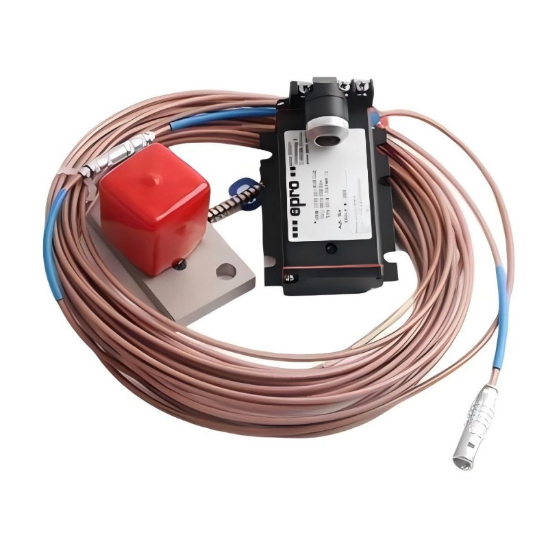
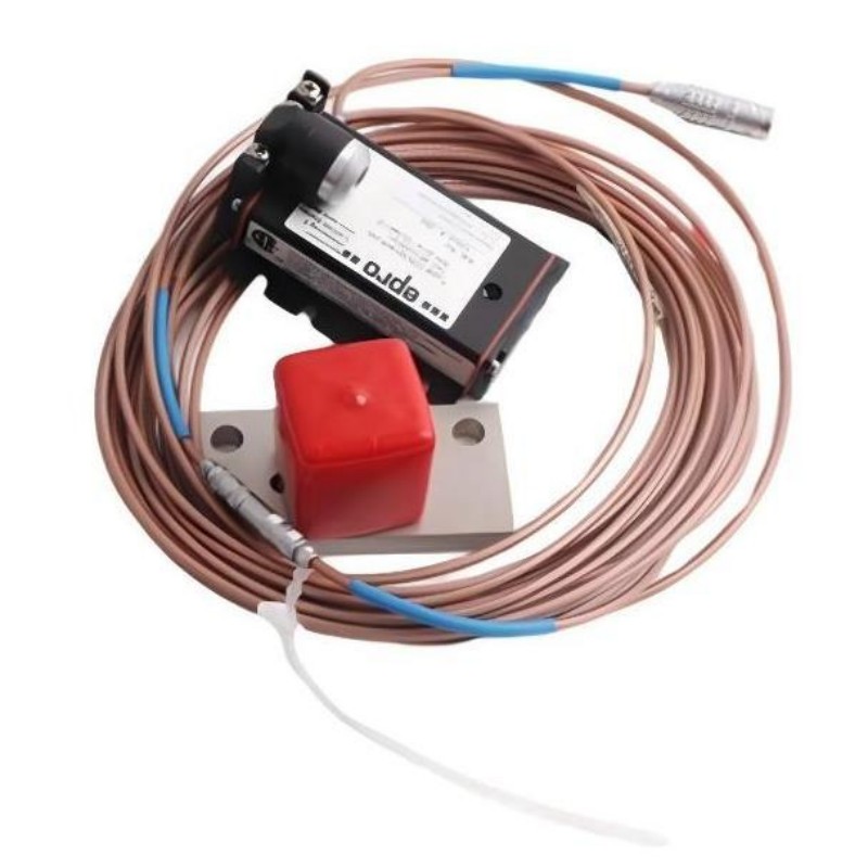
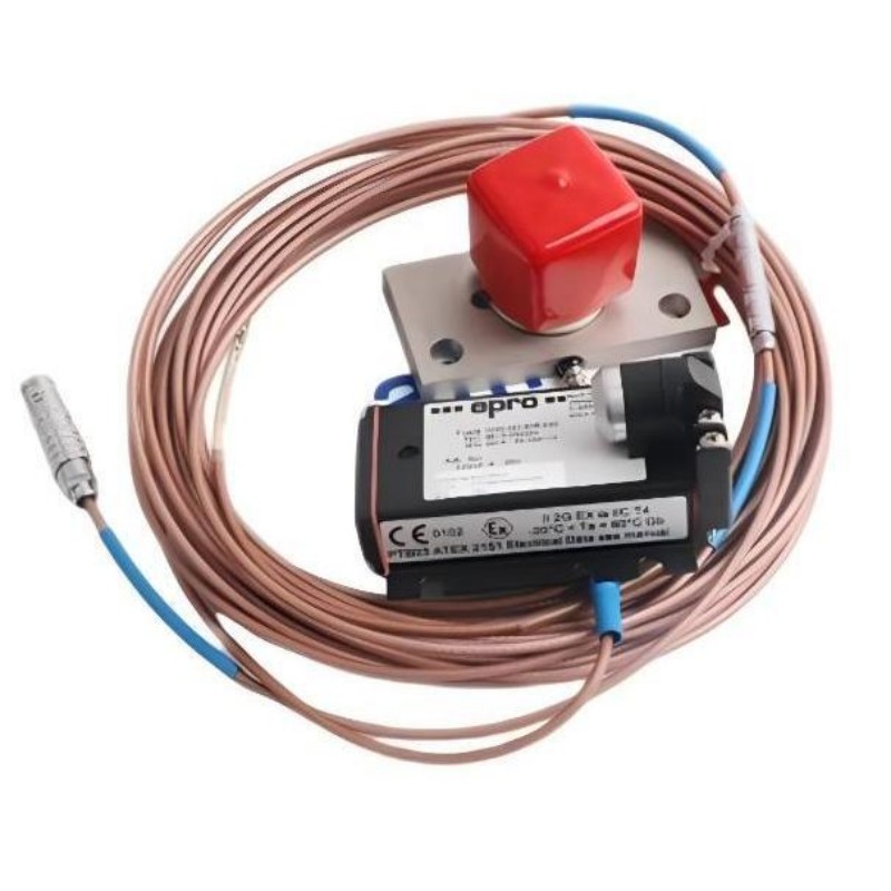
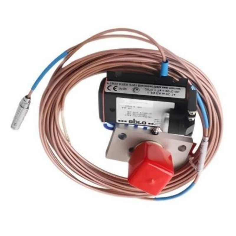
- Epro
- PR6426/010-000
- 32 mm Eddy Current Sensor
- Germany
- 32 mm
- 0.8 kg
- Xiamen, China
- New & In Stock
- T/T, PayPal, Western Union
- 1 Year
- 1-3 Working Days
- DHL, UPS, TNT, FedEx and EMS.
- 24-Hour Service
- COO
- 3
Our advantage

Global Logistics
We have a 10-year logistics and express cooperation agreement, so our products can be shipped to any place in the world.

Brand new and original
Our products are imported in bulk from the place of origin. Because of the cooperative relationship, our products are all original and 100% new.

24-hour service
We provide 7*24 hours service to our customers. We will be there whenever you need us.

Price advantage
All our products are priced very favorably because we have our own warehouse and supply.
| Company Information | |||
| [email protected] | |||
| Mobile | +8615980777398 | ||
| +8615980777398 | |||
| 15980777398 |
Product Overview
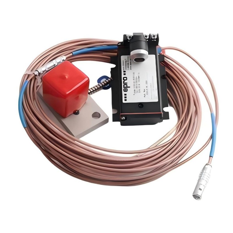
The Epro PR6426/010-000 is a 32 mm eddy current sensor for non-contact measurement of shaft displacement in critical rotating machinery. It belongs to the PR6426 family used in turbine, compressor, pump, and fan monitoring applications, where shaft position must be measured without allowing the sensing element to contact the moving surface.
In a turbine bearing arrangement, shaft displacement measurements help engineers observe changes in the rotor’s position relative to the bearing housing. In a large compressor, the same measurement principle can be used to track axial or radial shaft movement and provide data for machinery-condition assessment. These measurements are particularly useful during startup, changes in operating load, and investigations into abnormal vibration or rotor movement.
The PR6426 uses electromagnetic coupling between its sensing head and a conductive target. As the distance changes, the electrical response of the sensor changes accordingly. A compatible signal converter processes this response into a displacement-related output that can be evaluated by the machinery monitoring system.
The 32 mm sensor head belongs to a measuring system with a nominal static range of ±4.0 mm and a nominal sensitivity of 2 V/mm under the standard measuring configuration. The actual measuring performance depends on the complete sensor-converter combination, the target material, and the installation gap.
The /010-000 suffix must be retained when identifying the required replacement. The PR6426 family includes several cable, connection, and mechanical configurations, and the shared sensor-head diameter does not establish that every variant can be exchanged directly. For maintenance work, the existing connection arrangement and measuring-chain calibration should be checked alongside the model designation.
Technical Specifications
| Parameter | Specification |
|---|---|
| Manufacturer | Epro |
| Model | PR6426/010-000 |
| Product Type | 32 mm Eddy Current Sensor |
| Measurement Principle | Non-contact eddy current |
| Sensor Head Diameter | 32 mm |
| Static Measuring Range | ±4.0 mm, standard configuration |
| Nominal Sensitivity | 2 V/mm |
| Nominal Center Air Gap | Approximately 5.5 mm |
| Standard Target Material | Ferromagnetic steel, 42CrMo4 |
| Operating Temperature Range | -35 to +175°C |
| Maximum Cable Temperature | 200°C |
| Short-Term Temperature Excursion | 200°C for less than 4 hours |
| Sensor Head Pressure Resistance | 6,500 hPa |
| Shock and Vibration | 5 g at 60 Hz and 25°C |
| Sleeve Material | Stainless steel |
| Cable Material | PTFE |
| Weight | 0.8 kg |
Product Features
- Non-contact displacement measurement: Detects changes in the distance between the sensor head and a conductive target without mechanical contact with the shaft. This is useful for continuous monitoring of rotating equipment.
- 32 mm sensing-head configuration: Supports large-shaft measurement applications in which the target geometry and surrounding installation clearance meet the PR6426 requirements.
- Defined static measurement range: The nominal ±4.0 mm range supports shaft-position measurements within the standard configuration. The usable range must be coordinated with the selected converter and expected shaft movement.
- Specified displacement sensitivity: The nominal 2 V/mm sensitivity establishes the standard relationship between target movement and the conditioned output signal.
- Low long-term drift: The PR6426 family specifies long-term drift below 0.3%, an important consideration when displacement readings are trended over extended operating periods.
- Industrial sensor construction: The stainless-steel sleeve and PTFE cable are suited to the environmental conditions specified for the sensor family.
- Converter-based signal processing: Works as part of a measuring chain in which compatible electronics excite the sensor and convert its response into a signal suitable for monitoring.
- Multiple configuration options across the family: Cable length, cable protection, connector arrangement, and other ordering details vary by configuration. The complete model suffix should be checked before selecting a replacement.
Working Principle
The PR6426/010-000 measures displacement by detecting changes in the electromagnetic interaction between its sensing coil and the conductive shaft surface. The compatible converter excites the sensor, creating an alternating electromagnetic field at the sensing head. When the field interacts with the target, eddy currents develop in the conductive material and affect the electrical response of the coil.
As the shaft moves relative to the fixed sensor, the coupling changes. The converter processes that change and produces an output corresponding to the target’s position within the calibrated range.
The measurement path is:
Conductive Shaft Target → PR6426/010-000 Sensor → Compatible Signal Converter → Monitoring or Evaluation Electronics
For shaft-position monitoring, the initial air gap establishes the sensor’s operating point. If the gap is incorrectly adjusted, the expected shaft movement may extend beyond the usable range or the output may operate outside the intended measurement region. The nominal center gap of approximately 5.5 mm applies to the standard PR6426 measuring configuration; it should not be treated as a universal setting for every converter arrangement.
Target material also matters. The standard measuring chain is calibrated for ferromagnetic steel, with 42CrMo4 as the reference material. A different shaft material can change the measurement response and may require a correspondingly adjusted measuring chain.
The sensor does not independently determine whether a shaft movement represents a fault. It supplies displacement information to the associated monitoring electronics, where the reading can be evaluated against machine operating conditions, established trends, and configured alarm limits. For this reason, sensor mounting, converter calibration, and monitoring settings must be treated as parts of the same measurement task.
Role in the Machinery Monitoring Architecture
The PR6426/010-000 occupies the sensing stage of a machinery-monitoring system. It measures relative displacement between the sensor head and a conductive target, while the connected converter and monitoring electronics turn that response into information that operators and maintenance personnel can use.
A typical measurement path is:
Rotating Shaft → PR6426 Sensor → Compatible Converter or Integrated Interface → Monitoring Electronics → Displacement Display and Alarm Processing
| System Element | Function |
|---|---|
| Epro PR6426/010-000 | Detects relative movement between the sensor head and the target |
| Rotating Shaft | Provides the conductive surface used for measurement |
| Sensor Mounting Assembly | Maintains the required position and alignment relative to the shaft |
| Sensor Cable and Connection | Carries the sensor connection to the associated electronics |
| Compatible Signal Converter | Excites the sensor and conditions its electrical response |
| Monitoring or Evaluation Module | Processes the displacement signal for display, trending, or alarm evaluation |
| Machinery Protection System | Applies the configured limits and protection logic where supported |
| Plant Monitoring Interface | Presents measurement information for operating and maintenance decisions |
In a turbine installation, sensors positioned around the shaft can supply measurements for different displacement directions. In a compressor, displacement information may be evaluated alongside vibration, speed, and process conditions to help distinguish mechanical movement from changes associated with operating load.
The converter is not merely a signal connection accessory. Its calibration and output characteristics determine how the sensor response is interpreted. A replacement sensor should therefore be checked against the existing converter and monitoring configuration before its readings are compared with historical data.
Industrial Applications
| Application | Practical Use |
|---|---|
| Steam Turbines | Monitoring shaft displacement during startup, normal operation, and changes in operating conditions |
| Gas Turbines | Measuring relative rotor movement in critical rotating assemblies |
| Hydro Turbines | Tracking shaft position in large turbine installations |
| Industrial Compressors | Observing shaft displacement as part of compressor condition monitoring |
| Centrifugal Pumps | Measuring shaft movement where continuous non-contact monitoring is required |
| Large Industrial Fans | Tracking shaft-position changes in rotating equipment |
| Power Generation Plants | Supplying displacement measurements for machinery monitoring and maintenance assessment |
| Petrochemical Facilities | Monitoring critical rotating machinery in process installations |
| Machinery Overhaul Projects | Replacing a sensor while preserving the established measuring-chain configuration |
| Predictive Maintenance Programs | Recording displacement trends for comparison with vibration and operating data |
Installation and Maintenance
- Verify the full model designation: Confirm PR6426/010-000 against the installed sensor identification and maintenance records. Do not select a replacement based solely on the PR6426 family name or 32 mm head diameter.
- Confirm converter compatibility: Check the installed converter or monitoring interface against the sensor’s required connection and measuring configuration. Verify the calibration and output characteristics before connecting the replacement.
- Check the shaft target material: Confirm that the measured surface meets the requirements of the existing calibrated measuring chain. The standard reference material is ferromagnetic steel, 42CrMo4.
- Prepare the mounting arrangement: Inspect the mounting plate, support, and fixing points. The sensor holder must remain rigid during operation so that holder movement does not appear as shaft displacement.
- Adjust the initial gap: Set the distance between the sensor head and the target using the approved measuring-chain adjustment procedure. The nominal center gap is approximately 5.5 mm for the standard configuration.
- Maintain the required clearance: Check for nearby ferrous material that could affect the electromagnetic field. The PR6426 installation arrangement requires attention to the surrounding metal clearance and the target area.
- Inspect the sensing head: Examine the sensor head and sleeve for mechanical damage, deformation, or contamination. Check the mounting surfaces before reinstalling the unit.
- Protect the cable during installation: Avoid twisting, crushing, or sharply bending the cable. Maintain the minimum bending radius applicable to the actual cable construction and inspect the cable route for contact with hot or moving components.
- Check the connector arrangement: Verify that the installed cable and connector match the receiving converter or interface. Do not assume that different PR6426 suffixes have identical connection details.
- Verify the output during commissioning: Use the approved converter adjustment procedure to check that the signal changes in the expected direction as the target position changes. Confirm the correct operating point before enabling the measurement for normal service.
- Evaluate readings against operating conditions: Check whether an unusual signal coincides with startup, load changes, mechanical vibration, or a possible wiring fault. Investigate the cause before changing alarm thresholds or protection settings.
- Record the final configuration: Document the sensor model, converter identification, initial gap, cable arrangement, measured output, and commissioning results. These records help maintain consistency when the sensor is inspected or replaced later.
Compatible System Components
| Component | Function |
|---|---|
| Epro CON011 Converter | Supports compatible PR642x eddy current measuring chains |
| Epro CON021 Converter | Provides signal conditioning for supported sensor configurations |
| Epro CON031 Converter | Supports compatible sensor-to-converter arrangements |
| Epro CON041 Converter | Provides a converter option for supported eddy current measuring chains |
| Compatible MMS 3000 Transmitters | Integrate supported sensor-converter functions into machinery monitoring |
| AMS 3000 Series Monitoring Equipment | Supports measurement integration where the installed configuration is compatible |
| Sensor Mounting Assembly | Holds the sensing head in the required measurement position |
| Compatible Cable and Connection Hardware | Establishes the connection between the sensor and its measuring electronics |
| Conductive Shaft Target | Provides the surface whose relative position is measured |
The exact combination must be checked against the installed configuration. Compatibility with the broader PR6426 family does not, by itself, confirm that a particular converter, connector, or cable arrangement is interchangeable with the PR6426/010-000.
Recommended Related Models
| Model | Product Type | Selection Consideration |
|---|---|---|
| Epro PR6426/010-100 | 32 mm Eddy Current Sensor | Compare the complete ordering code and connection arrangement before considering substitution |
| Epro PR6426/010-110 | 32 mm Eddy Current Sensor | Verify the exact variant and its compatibility with the existing measuring chain |
| Epro PR6426/010-130 | 32 mm Eddy Current Sensor | Check the specified cable and mechanical configuration against the installed sensor |
| Epro PR6426/010-140 | 32 mm Eddy Current Sensor | Confirm the full model designation and converter requirements before replacement |
| Epro PR6426/000-140 | 32 mm Eddy Current Sensor | Compare the ordering-code configuration rather than assuming direct interchangeability |
Key Advantages
- Non-contact measurement of shaft displacement.
- Nominal static measuring range of ±4.0 mm in the standard configuration.
- Nominal sensitivity of 2 V/mm with compatible signal conditioning.
- Stainless-steel sleeve and PTFE cable construction.
- Integration into compatible turbine and rotating-machinery monitoring systems.
Technical FAQs
What needs to be matched when installing a PR6426/010-000 in an existing monitoring system?
The sensor’s full ordering code, cable and connector arrangement, converter compatibility, target material, and calibration must match the intended measurement configuration. The same head diameter alone is not sufficient to confirm compatibility.
Why is a rigid sensor holder necessary for shaft-displacement measurement?
The sensor measures movement relative to its mounting position. If the holder vibrates or shifts, that movement can be included in the measured signal and mistaken for actual shaft displacement. A rigid, vibration-free mounting arrangement helps preserve measurement accuracy.
Can the sensor’s standard measuring range be extended?
The PR6426 family supports different measuring configurations through compatible converter arrangements. An extended range should only be used when the specific converter configuration supports it and the sensor is adjusted accordingly; the standard ±4.0 mm specification should not be assumed to apply unchanged to every configuration.
What should maintenance personnel investigate when the measured displacement changes unexpectedly?
Check the initial gap, sensor mounting, cable and connection condition, converter configuration, and target surface. Compare the reading with machine speed, load, and other monitoring signals to help determine whether the change reflects actual shaft movement or a problem in the measurement chain.