

ProductPRODUCT
Featured products
Contact Us
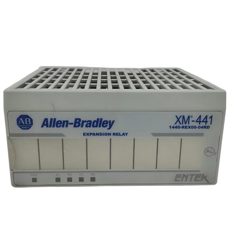
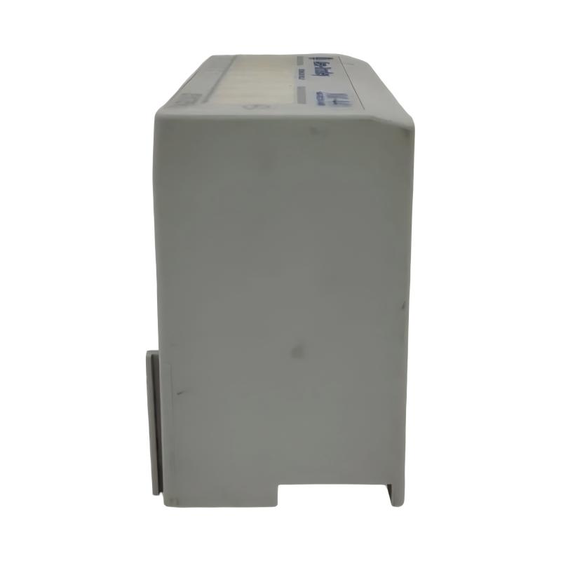
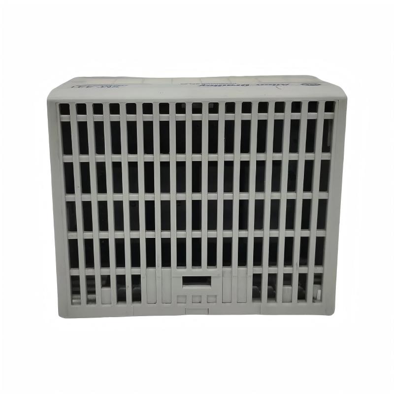
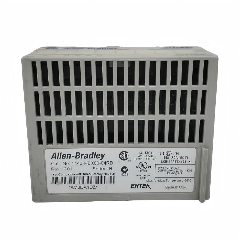
- Allen Bradley
- XM-441 1440-REX00-04RD
- XM-441 Extended Relay Module
- USA
- 97 x 94 x 94 mm
- 0.34 kg
- Xiamen, China
- New & In Stock
- T/T, PayPal, Western Union
- 1 Year
- 1-3 Working Days
- DHL, UPS, TNT, FedEx and EMS.
- 24-Hour Service
- COO
- 6
Our advantage

Global Logistics
We have a 10-year logistics and express cooperation agreement, so our products can be shipped to any place in the world.

Brand new and original
Our products are imported in bulk from the place of origin. Because of the cooperative relationship, our products are all original and 100% new.

24-hour service
We provide 7*24 hours service to our customers. We will be there whenever you need us.

Price advantage
All our products are priced very favorably because we have our own warehouse and supply.
| Company Information | |||
| [email protected] | |||
| Mobile | +8615980777398 | ||
| +8615980777398 | |||
| 15980777398 |
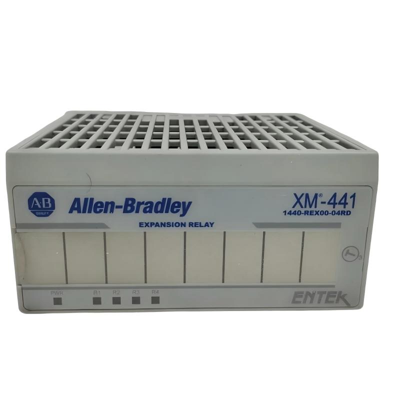
1. Product Overview
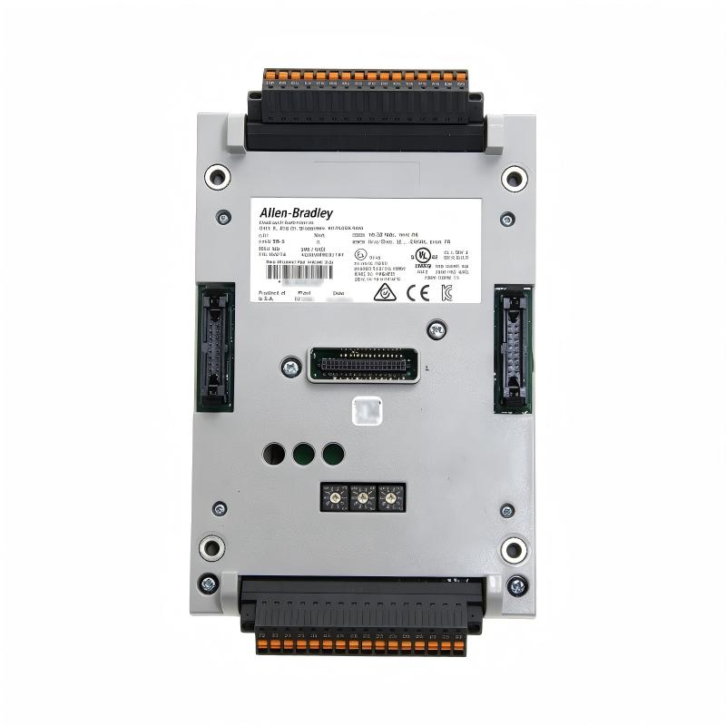
The Allen-Bradley XM-441 Expansion Relay Module, catalog number 1440-REX00-04RD, is an industrial relay expansion device designed for the Allen-Bradley XM series of machinery condition monitoring and protection systems. Its primary function is to provide four additional relays for compatible XM measurement modules or the XM-440 Master Relay Module.
In industrial automation, condition monitoring systems evaluate parameters such as vibration, speed, position, and other machine operating conditions. When a monitored value reaches a configured threshold, the host monitoring module can initiate an appropriate response. The XM-441 extends the available relay output capacity, allowing additional alarms, status signals, and control interfaces to be connected to external equipment.
The XM-441 contains four double-pole, double-throw (DPDT) relays. Each relay provides normally open and normally closed contacts, giving system designers flexibility when connecting alarm circuits and other compatible electrical loads. The contacts can be used for applications such as annunciation, control-system status reporting, and interfacing with external equipment, subject to the relay ratings and system design.
Unlike an intelligent monitoring module, the XM-441 does not independently measure vibration or process conditions. It operates as an expansion module connected to a compatible XM host through the side connector. The host module manages the relay logic and associated functions, including activation, latching, time delay, reset, and fail-safe behavior where supported and configured.
The module is designed for use with the specified XM terminal base, catalog number 1440-TB-D. It receives its operating power through the XM system connection arrangement and works as part of the wider monitoring installation. Correct compatibility, terminal-base selection, wiring, grounding, and relay configuration are essential for reliable operation.
For industrial plants maintaining existing XM machinery monitoring systems, the XM-441 provides a way to expand relay functionality without replacing the complete monitoring architecture. It can be useful in applications where additional alarm contacts or equipment interfaces are required.
2. Technical Specifications
| Parameter | Specification |
|---|---|
| Brand | Allen-Bradley |
| Product Series | XM Series |
| Model | XM-441 |
| Catalog Number | 1440-REX00-04RD |
| Product Type | Expansion Relay Module |
| Primary Function | Adds relay outputs to a compatible XM host |
| Number of Relays | 4 |
| Relay Contact Configuration | DPDT, two Form C contact sets per relay |
| Contact Types | Normally Open (NO) and Normally Closed (NC) |
| Relay Contact Rating | 250 V AC, 50/60 Hz, 3 A resistive |
| Fail-Safe Options | Normally energized or normally de-energized, according to host configuration and application |
| Host Interface | Local XM side connector |
| Compatible Host Devices | Compatible XM measurement modules and XM-440 Master Relay Module |
| Terminal Base | 1440-TB-D |
| Supply Voltage | 24 V DC |
| Maximum Supply Current | 0.2 A |
| Maximum Power Dissipation | 2.9 W |
| Operating Temperature | -20°C to +65°C |
| Storage Temperature | -40°C to +85°C |
| Relative Humidity | Up to 95%, non-condensing |
| Dimensions | 97 × 94 × 94 mm |
| Weight | 0.34 kg |
| Mounting | Specified XM terminal base, DIN rail or suitable grounded panel installation |
| Typical Applications | Machinery alarms, condition monitoring, relay expansion, external control interfaces |
Electrical ratings and installation requirements should be verified against the documentation applicable to the exact module revision. The 3 A relay rating is specified for resistive loads; motor loads, inductive loads, and other switching applications require additional assessment.
3. Function and Working Principle
3.1 Expansion of Relay Outputs
The main purpose of the XM-441 is to add four relays to a compatible XM monitoring system. A host module may already monitor machine conditions and provide its own alarm or relay functions. When additional independent contacts are needed, the XM-441 can extend the number of available relay circuits.
For example, a machinery monitoring installation might need separate outputs for a warning alarm, a high-level alarm, a maintenance indication, and an external control-system signal. The XM-441 can provide additional relay contacts for such functions when they are supported and configured by the host module.
The specific assignment of each relay depends on the application and the host module’s configuration capabilities.
3.2 DPDT Relay Contact Operation
Each of the four relays uses a double-pole, double-throw contact arrangement. This provides two sets of changeover contacts that operate together when the relay changes state.
Each set includes a common terminal, a normally open contact, and a normally closed contact. When the relay is in its normal state, the normally closed contact is connected to common and the normally open contact is disconnected. When the relay is activated, the contact state changes.
This arrangement allows engineers to select the contact type that suits the receiving circuit. For example, a normally open contact may be used to close an alarm circuit when a relay activates, while a normally closed contact may be used in an appropriately designed monitoring circuit.
The actual behavior depends on whether the host configuration uses normally energized or normally de-energized operation. Contact selection must therefore be based on the intended alarm logic and the consequences of loss of power or communication.
3.3 Control by the XM Host Module
The XM-441 is not an independent monitoring controller. It does not directly measure vibration, temperature, speed, or other machine parameters.
Instead, it receives its operating and control signals from the compatible host module through the XM side connector. The host determines when a relay should activate based on its own monitoring configuration, supported logic, and the application requirements.
This arrangement separates measurement and decision-making from additional relay switching capacity. The host handles monitoring and relay control, while the XM-441 supplies the extra physical contacts required by the installation.
No separate network node address is required for the XM-441 because it extends the host module’s circuitry rather than acting as an independent DeviceNet node.
3.4 Alarm and Status Signaling
The additional relay contacts can be used to communicate selected alarm or status conditions to external equipment. Depending on the system design, these contacts may connect to a PLC digital input, an annunciator, an indicator circuit, or another compatible control interface.
For example, a host monitoring module may be configured to detect a high vibration condition. When the corresponding relay logic activates, a relay contact can change state and notify the control system or trigger an appropriate external response.
The XM-441 itself does not decide whether a vibration value is abnormal. That decision is made by the host monitoring module according to the configured thresholds and logic.
3.5 Fail-Safe and Non-Fail-Safe Operation
The XM system supports normally energized, fail-safe operation and normally de-energized, non-fail-safe operation where supported by the host module and configured application.
In a normally energized arrangement, the relay is energized during the normal state and changes state when the configured condition occurs or when the relevant circuit loses power. This approach can help make certain fault conditions visible, but the complete circuit design must be evaluated.
In a normally de-energized arrangement, the relay is activated when the configured condition requires it. The appropriate choice depends on the application, alarm philosophy, host capabilities, and the behavior required during loss of power.
Fail-safe behavior should never be assumed solely from the presence of an XM-441. Engineers must verify the host configuration, contact wiring, and expected system response.
3.6 Relay Status Indicators
The XM-441 includes a power status indicator and four relay status indicators. The power indicator identifies whether module power is present, while the individual relay indicators show the activation state of the corresponding relays.
These indicators help maintenance personnel distinguish a power-related issue from a relay that is simply not activated by the host. They should be used alongside the host module’s status information and the electrical measurements obtained during troubleshooting.
4. Role in Industrial Control Systems
4.1 Expanding Machinery Protection Interfaces
Industrial machinery monitoring systems may need to communicate several different conditions to external equipment. The XM-441 provides additional relay contacts that can be assigned to supported host functions.
This is useful when an installation requires more hardwired alarm or status circuits than the host module alone can provide. The additional contacts can help organize alarm signals and support integration with existing control panels.
4.2 Connecting Monitoring Systems to PLCs
A compatible PLC can receive relay status through its digital input circuits. This allows the PLC program to display alarm states, record events, or coordinate selected process actions.
The XM-441 does not communicate directly with the PLC as an independent controller. Instead, its relays are managed by the connected XM host, and the PLC receives the resulting contact states through the external wiring arrangement.
When designing this interface, engineers should verify input voltage, current, contact ratings, electrical isolation requirements, and the intended response to loss of power.
4.3 Supporting Alarm Annunciation
Multiple machine conditions may require separate warning, alarm, and maintenance signals. Additional relay contacts can provide dedicated hardwired indications to an annunciator or other compatible alarm system.
Separating different conditions into clearly documented circuits can simplify troubleshooting and help operators understand which machine condition requires attention.
4.4 Integrating with Existing XM Installations
The XM-441 is particularly relevant to plants that already use compatible XM measurement modules or the XM-440 Master Relay Module.
Where the existing host and monitoring configuration remain suitable, adding the expansion relay module may be a more straightforward approach than replacing the entire monitoring system. Compatibility and the host’s support for the intended relay functions must be confirmed before installation.
4.5 Supporting Maintenance and Troubleshooting
The module’s relay indicators provide a local way to check whether the individual relays are activated. Maintenance personnel can compare these indications with the host module’s configured state and the actual electrical condition of the connected circuits.
This helps narrow the investigation when an external alarm is not received or a relay output appears to behave unexpectedly.
5. Typical Industrial Applications
5.1 Motor Condition Monitoring
Electric motors are used in manufacturing, pumping, conveying, and process equipment. When a compatible XM host monitors motor vibration or other machine parameters, additional relay contacts can be used to communicate selected alarm conditions.
The XM-441 can provide separate hardwired outputs for compatible warning and alarm functions, depending on the host configuration.
5.2 Pumps and Pumping Stations
Pump installations may use condition monitoring to identify abnormal vibration or other equipment issues. Additional relay contacts can help communicate selected monitoring states to a PLC, control panel, or alarm annunciator.
The relay module does not measure pump condition itself; it provides additional output contacts controlled by the host monitoring device.
5.3 Fans and Blowers
Industrial fans and blowers often operate for long periods. A monitoring system may be configured to detect changes in vibration or other parameters that warrant investigation.
The XM-441 can extend the number of available relay outputs so that selected conditions can be presented to external equipment through separate contact circuits.
5.4 Compressors and Rotating Equipment
Compressors and other rotating machinery may require several independent alarm interfaces. Additional relay contacts can be useful when the monitoring architecture requires more hardwired signals for status indication or control-system integration.
The host module and overall system must be appropriate for the machine’s operating requirements. Critical protection functions should use equipment and architectures that meet the applicable safety and protection requirements.
5.5 Industrial Process Plants
Process plants often integrate machinery monitoring with PLCs, distributed control systems, annunciators, and operator panels. Relay expansion can help provide the hardwired signals needed to connect a monitoring system with existing control equipment.
Typical examples include utility systems, industrial water systems, material handling, and rotating process machinery.
5.6 Existing Machinery Protection Systems
For facilities that maintain established Allen-Bradley XM systems, the XM-441 can be used to expand relay output capacity where the existing host supports the required functions.
Before adding a module, engineers should verify the host model, supported expansion arrangement, terminal base, power requirements, relay assignment, and external circuit design.
6. Installation and System Integration
Correct installation is essential for dependable relay operation. The XM-441 must be connected to a compatible host module and installed using the specified terminal base.
6.1 Verify the Catalog Number and Host Compatibility
Before installation or replacement, confirm the complete catalog number 1440-REX00-04RD.
Check the host module’s documentation to ensure that it supports the XM-441 and the required relay functions. The XM-441 can be used with compatible XM measurement modules or the XM-440 Master Relay Module.
XM measurement modules support only one expansion module, which must be placed immediately to the right of and directly connected to the host module. Confirm the permitted arrangement for the specific system.
6.2 Use the Correct Terminal Base
The XM-441 uses the 1440-TB-D terminal base. Verify the terminal-base catalog number before wiring or commissioning the system.
Install the terminal base according to the manufacturer’s instructions, ensuring secure mounting and the required grounding connection. The XM-441 is an open-style device and should be installed in an appropriate protective enclosure for its industrial environment.
6.3 Check the 24 V DC Supply
The module uses a 24 V DC supply, with a maximum supply current of 0.2 A according to the specified technical data.
Confirm that the supply voltage is within the permitted range, that the power source can support the system load, and that wiring polarity and terminal connections are correct.
Before installing or removing modules, follow the approved electrical isolation procedures for the control system.
6.4 Connect the Relay Contacts
Wire the relay contacts according to the intended application and the terminal diagrams for the specific terminal base.
For each relay, identify the common, normally open, and normally closed terminals. Confirm which contact state corresponds to the configured host behavior and test the circuit before returning the equipment to service.
The stated 250 V AC, 3 A rating applies to resistive loads. Inductive loads, motor circuits, and loads with high inrush current may require interposing relays or other suitable interface devices. Verify the electrical ratings and switching requirements before connecting any load.
6.5 Configure the Host Module
The XM-441 does not require independent relay programming. Relay assignments and functions are configured through the connected host XM module.
Depending on the host’s capabilities, these settings may include relay activation, latching, time delay, reset logic, and fail-safe behavior. Review the host’s configuration carefully to ensure that the intended condition operates the correct relay.
Keep a record of the relay assignments, normal contact states, alarm thresholds, and external circuits associated with each relay.
6.6 Verify Grounding and Wiring Practices
The XM system’s grounding arrangement is important for electrical safety and noise control. Follow the manufacturer’s requirements for DIN rail or panel mounting and ensure the mounting structure is appropriately grounded.
Use shielded wiring for signal connections where specified. Power and relay wiring should be routed according to the installation instructions and separated from sensitive signal wiring where required.
Poor grounding or incorrect wiring can create intermittent faults, false indications, or unexpected relay behavior.
6.7 Commissioning and Functional Testing
Before returning the equipment to service, verify:
- Correct XM-441 and terminal-base model numbers
- Compatibility with the selected host module
- Secure module and side-connector installation
- Correct 24 V DC power supply
- Proper grounding and enclosure protection
- Correct wiring of NO, NC, and common contacts
- Appropriate host relay assignments and logic
- Correct normal and activated relay states
- Expected operation of the four relay indicators
- Correct response at the connected PLC, annunciator, or external device
Testing should include the relevant alarm conditions and any required behavior during loss of power. The test procedure must be appropriate to the machine and must not create unsafe operating conditions.
7. Compatible System Components
The XM-441 operates as an expansion module within a compatible XM system. The following components may be relevant to an installation.
| Component | Function |
|---|---|
| XM-441 Expansion Relay Module | Provides four additional DPDT relays |
| 1440-REX00-04RD | Complete catalog number for the XM-441 relay module |
| 1440-TB-D Terminal Base | Provides the specified mounting and field-wiring interface |
| Compatible XM measurement module | Monitors machine parameters and manages supported relay functions |
| XM-440 Master Relay Module | Provides host relay functions and supports compatible expansion |
| 24 V DC power supply | Supplies operating power to the XM system |
| PLC digital input module | Receives hardwired relay contact status |
| Alarm annunciator | Presents selected alarm conditions to operators |
| Industrial control panel | Houses interface wiring and related control components |
| Suitable enclosure | Protects the open-style module and terminals from the installation environment |
| DIN rail or grounded mounting panel | Supports installation and the required grounding arrangement |
Compatibility must be confirmed for the specific host module, terminal base, hardware revision, and installation. The XM-441 does not replace the measurement capabilities of the host device.
8. Alternative Models and Replacement Considerations
When selecting a replacement, it is important to distinguish an expansion relay module from a master relay module or a measurement module. These devices serve different functions and are not automatically interchangeable.
| Replacement Approach | Key Considerations |
|---|---|
| Another XM-441, 1440-REX00-04RD | Verify the complete catalog number, revision, condition, and compatibility with the host |
| Compatible XM-440 Master Relay Module | This is a different system component, not a direct replacement for the XM-441; assess the required host and relay architecture |
| Another XM expansion relay product | Confirm the relay count, terminal base, contact ratings, mounting arrangement, and host compatibility |
| External interposing relay assembly | May provide additional contacts but requires a separate design for wiring, power, isolation, and control behavior |
| Modern machinery monitoring platform | Requires assessment of monitoring functions, relay logic, wiring, configuration migration, and downtime |
An external relay assembly may be suitable for certain applications, but it should not be assumed to reproduce all XM system features. The host-managed logic and expansion interface must be considered when evaluating alternatives.
Before purchasing, record the original module’s catalog number, host module model, terminal base, relay assignments, contact ratings, and wiring diagram. For used or refurbished units, verify physical condition, functional testing, warranty coverage, and return terms.
9. Key Advantages of the XM-441
Four Additional Relay Outputs
The XM-441 adds four relays to a compatible XM host, providing extra contacts for selected alarm and status circuits.
DPDT Contact Arrangement
Each relay provides two sets of changeover contacts, allowing normally open or normally closed contact arrangements to be selected according to the circuit design.
Host-Managed Operation
The host module manages the relay functions, allowing the XM-441 to extend the existing monitoring architecture rather than operating as a separate intelligent controller.
Support for Alarm Integration
The additional contacts can be connected to compatible PLC inputs, annunciators, or other external equipment to communicate selected system conditions.
Compact Installation
With dimensions of 97 × 94 × 94 mm according to the product specification, the module is designed for use within the XM terminal-base arrangement.
Local Status Indicators
The power indicator and four relay indicators assist technicians in checking the module’s power and relay activation states.
Application Flexibility
The additional contacts can be used in different alarm and status circuits when the host supports the required behavior and the connected loads remain within the permitted electrical ratings.
Useful for Existing XM Systems
For plants with compatible XM monitoring equipment, the XM-441 can expand relay capacity without requiring the complete system to be replaced solely to obtain additional contacts.
10. Frequently Asked Questions
Q1. What is the Allen-Bradley XM-441 used for?
The XM-441 is an expansion relay module that adds four relays to a compatible Allen-Bradley XM measurement module or XM-440 Master Relay Module.
Q2. What is the full catalog number?
The catalog number is 1440-REX00-04RD.
Q3. How many relays does the XM-441 have?
It contains four DPDT relays. Each relay has two sets of changeover contacts.
Q4. What is the contact rating?
The specified rating is 250 V AC, 50/60 Hz, 3 A for resistive loads. Other load types require careful evaluation against the applicable relay ratings.
Q5. Does the XM-441 measure vibration?
No. The XM-441 provides additional relay contacts. Vibration or other machine measurements are handled by the compatible host monitoring module.
Q6. Does it require a separate DeviceNet address?
No. The XM-441 communicates with its host through the XM side connector and does not consume an independent DeviceNet node address.
Q7. Which terminal base is required?
The specified terminal base is 1440-TB-D. Confirm the terminal-base catalog number before installation or replacement.
Q8. Does the module require 24 V DC power?
Yes. Its specified supply is 24 V DC, with a maximum supply current of 0.2 A. Follow the applicable installation documentation for the complete power and wiring requirements.
Q9. Can the XM-441 be configured independently?
No. Its relay behavior is configured through the compatible host XM module. The host manages supported relay functions such as activation, latching, time delay, logic, and reset.
Q10. Can the XM-441 drive a motor directly?
The relay contacts are rated for 3 A at 250 V AC for resistive loads. A motor is an inductive load and may have a high starting current, so direct switching should not be assumed suitable. A properly rated contactor or interface relay may be required.
Q11. What should be checked if a relay does not activate?
Check the host module’s configuration and status, the configured alarm condition, the side connector, module power, terminal-base wiring, and relay indicator. Then verify the external circuit and contact wiring.
Q12. Can any XM relay module replace the XM-441?
No. Different XM modules have different roles, contact arrangements, terminal bases, and host requirements. Verify the full catalog number and system compatibility before selecting an alternative.
11. Procurement and Maintenance Recommendations
When sourcing an XM-441 for an industrial spare-parts inventory, confirm the exact model and its intended host application. A relay module may look similar to other XM products while having different interfaces or functions.
The following checks are recommended:
- Catalog number: Confirm 1440-REX00-04RD on the module label.
- Host compatibility: Verify that the connected XM measurement or master relay module supports the expansion relay module.
- Terminal base: Confirm the required 1440-TB-D terminal base.
- Relay condition: Check relay operation and inspect the contact terminals for damage or corrosion.
- Electrical ratings: Ensure the external loads are compatible with the relay contact ratings.
- Configuration records: Document the host relay assignments, normal states, latching behavior, delays, and reset logic.
- Supplier verification: Check the unit’s condition, testing information, warranty, and return policy.
- Installation safety: Follow electrical isolation procedures and verify grounding before maintenance work.
During routine maintenance, inspect terminal connections, module seating, grounding, and enclosure condition. Check the power indicator and each relay indicator, and compare their states with the host configuration.
If an external alarm does not operate as expected, determine whether the problem originates in the host configuration, module connection, relay contacts, or external circuit. Replacing the XM-441 without checking the host and wiring may not resolve the underlying issue.
After a replacement, test each required relay function and verify the expected response at the receiving control system. Record the results and update the wiring and configuration documentation.
12. Conclusion
The Allen-Bradley XM-441 Expansion Relay Module, catalog number 1440-REX00-04RD, provides four additional DPDT relays for compatible XM machinery monitoring systems. It is designed to extend the relay output capacity of a supported XM measurement module or XM-440 Master Relay Module, enabling additional alarm, status, and external control interfaces.
With its 24 V DC supply, host-managed operation, local status indicators, and compact installation format, the XM-441 is a practical component for maintaining and expanding compatible XM installations.
For maintenance engineers, system integrators, and industrial spare-parts purchasers, the most important considerations are host compatibility, the correct terminal base, relay contact ratings, external circuit design, and proper configuration. Confirming these details before purchase and validating all relay functions after installation can help support dependable operation of the wider machinery monitoring system.