

ProductPRODUCT
Featured products


Contact Us
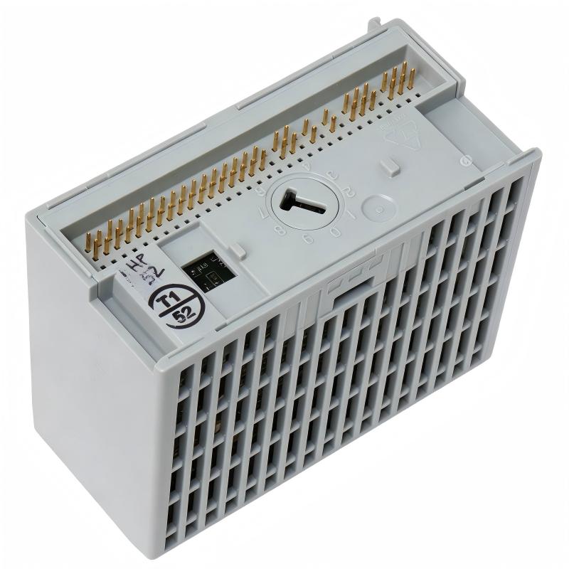
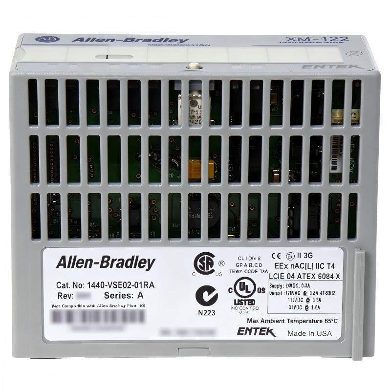
- Allen Bradley
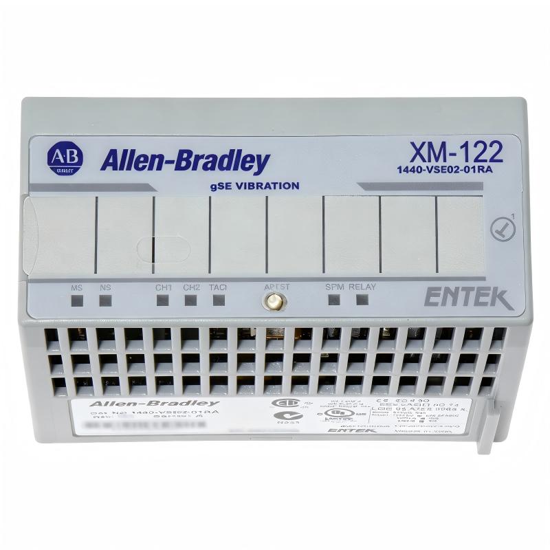
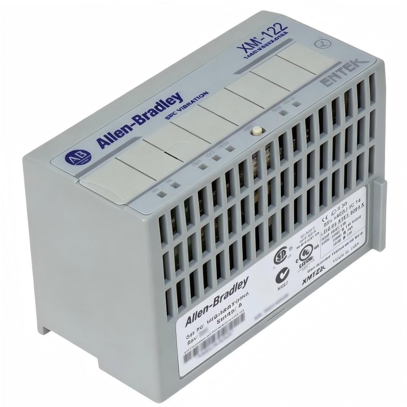
- XM-122 1440-VSE02-01RA
- XM-122 gSE Vibration Module
- USA
- 97 x 94 x 94 mm
- 0.34 kg
- Xiamen, China
- New & In Stock
- T/T, PayPal, Western Union
- 1 Year
- 1-3 Working Days
- DHL, UPS, TNT, FedEx and EMS.
- 24-Hour Service
- COO
- 5
Our advantage

Global Logistics
We have a 10-year logistics and express cooperation agreement, so our products can be shipped to any place in the world.

Brand new and original
Our products are imported in bulk from the place of origin. Because of the cooperative relationship, our products are all original and 100% new.

24-hour service
We provide 7*24 hours service to our customers. We will be there whenever you need us.

Price advantage
All our products are priced very favorably because we have our own warehouse and supply.
| Company Information | |||
| [email protected] | |||
| Mobile | +8615980777398 | ||
| +8615980777398 | |||
| 15980777398 |
1. Product Overview
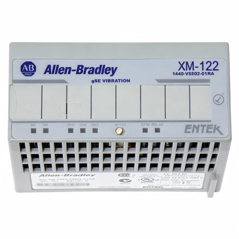
The Allen-Bradley XM-122 gSE Vibration Module, catalog number 1440-VSE02-01RA, is an intelligent condition monitoring device designed to measure vibration and specialized bearing-related signals in industrial machinery. It belongs to the Allen-Bradley XM series of condition monitoring products and is designed for applications where machinery health, operating stability, and early fault detection are important.
Unlike a conventional PLC input module, the XM-122 contains dedicated measurement electronics and processing capabilities for analyzing dynamic signals. It can accept signals from compatible vibration transducers, perform configured measurements, and provide measurement information through communication and analog output interfaces. The module also supports a tachometer input for speed-related measurements and analysis.
One of its distinguishing features is its ability to perform gSE, or g’s Spike Energy, measurements in addition to conventional vibration measurements. This specialized signal-processing technique is intended to help identify high-frequency vibration activity associated with rolling element bearing conditions. The usefulness of this measurement depends on the machinery, sensor selection, installation quality, and the configured monitoring parameters.
The XM-122 is suitable for selected applications involving motors, pumps, fans, compressors, gearboxes, and other rotating equipment. By continuously or periodically monitoring vibration-related parameters, maintenance teams can identify changes in machine behavior and investigate potential mechanical problems before they lead to unexpected downtime.
The module supports two vibration measurement channels and one tachometer input. Its outputs include two isolated 4–20 mA channels that can be configured to represent selected measurements, along with buffered signals for external monitoring equipment. DeviceNet communication enables integration with compatible industrial control and monitoring systems.
For facilities maintaining existing Allen-Bradley XM installations, the 1440-VSE02-01RA can serve as an important component in a machinery condition monitoring system. Correct sensor wiring, module configuration, communication setup, and interpretation of measured data are essential for reliable operation.
2. Technical Specifications
| Parameter | Specification |
|---|---|
| Brand | Allen-Bradley |
| Product Series | XM Series |
| Model | XM-122 |
| Catalog Number | 1440-VSE02-01RA |
| Product Type | gSE Vibration Monitoring Module |
| Primary Function | Vibration measurement and machinery condition monitoring |
| Vibration Input Channels | 2 |
| Tachometer Input | 1 |
| Supported Signal Types | Compatible eddy-current, accelerometer, velocity, and other dynamic measurement signals |
| gSE Measurement | Supported |
| Analog Outputs | 2 isolated 4–20 mA outputs |
| Buffered Outputs | One active buffered output per vibration input channel; tachometer buffering supported |
| Communication Interface | DeviceNet |
| Local Configuration Interface | RS-232 serial interface |
| DeviceNet Baud Rate | 125, 250, or 500 kbps, determined by the network |
| Module Supply Voltage | 21.6–26.4 V DC |
| Typical Module Current Consumption | Approximately 175 mA |
| Maximum Module Current Consumption | Approximately 300 mA |
| Typical Power Consumption | Approximately 4 W |
| Maximum Power Consumption | Approximately 7 W |
| Operating Temperature | -20°C to +65°C |
| Storage Temperature | -40°C to +85°C |
| Relative Humidity | Up to 95%, non-condensing |
| Dimensions | 97 × 94 × 94 mm |
| Weight | 0.34 kg |
| Mounting Arrangement | XM-940 terminal base |
| Typical Applications | Motors, pumps, fans, compressors, gearboxes, and rolling element bearing monitoring |
Specifications should be checked against the exact hardware revision and installation documentation before commissioning. Transducer power, signal ranges, output scaling, relay behavior, and supported measurements depend on configuration and the connected equipment.
3. Function and Working Principle
3.1 Conventional Vibration Measurement
Rotating machinery generates vibration during normal operation. Changes in vibration amplitude, frequency, or pattern can indicate developing mechanical issues such as imbalance, misalignment, looseness, or bearing deterioration.
The XM-122 receives dynamic signals from compatible vibration transducers connected to its input channels. Its internal electronics process these signals and calculate selected vibration parameters according to the configured measurement setup.
Depending on the sensor and configuration, monitored values can include overall vibration, frequency-related components, and other supported dynamic measurements. Maintenance engineers can use trends in these values to compare current machine behavior with an established baseline.
The module does not automatically identify every mechanical fault. Measurement interpretation requires knowledge of the machine, sensor location, operating speed, load conditions, and the characteristics of the vibration signal.
3.2 gSE Spike Energy Measurement
A key capability of the XM-122 is its gSE measurement function. This measurement is intended to detect high-frequency signal activity that may be associated with rolling element bearing conditions.
Bearing defects can generate short-duration impacts as rolling elements pass over damaged or irregular surfaces. Such impacts may produce high-frequency energy that is difficult to evaluate using overall vibration values alone.
The XM-122 uses specialized signal processing to provide gSE-related measurements alongside conventional vibration monitoring. This additional information can help maintenance personnel investigate bearing condition changes and establish more informative monitoring trends.
However, a rising gSE value is not by itself definitive proof of bearing failure. Lubrication conditions, machine operating state, sensor mounting, electrical interference, and other factors may influence measurements. Appropriate baseline data and engineering judgment remain essential.
3.3 Two-Channel Vibration Monitoring
The module provides two vibration input channels. This arrangement allows engineers to monitor two measurement locations or directions, depending on the machine design and sensor installation.
For example, a motor-driven pump may have vibration sensors mounted at selected bearing locations. Comparing the two channels can help maintenance personnel identify changes in vibration distribution and decide whether further inspection is necessary.
The two channels can be configured according to the application. Sensor types, input ranges, measurement units, and other parameters should be set to match the connected transducers.
3.4 Tachometer and Speed Measurement
The XM-122 includes a tachometer input for compatible speed signals. Speed information helps provide context for vibration measurements because many vibration characteristics are related to shaft rotation.
The module supports configured speed and frequency measurements and can provide phase- and order-related information when the sensor arrangement and configuration support these functions.
For rotating machinery, order-related analysis can help engineers examine vibration components in relation to shaft speed. Correct tachometer installation and signal configuration are therefore important for meaningful results.
3.5 Analog Output Processing
Two isolated 4–20 mA outputs allow selected measurements to be represented as industrial analog signals. Each output can be configured to track an available measurement, such as a selected vibration parameter, speed, or supported gSE value.
A compatible PLC analog input, distributed control system, or process monitoring device can receive the scaled signal. This provides a way to display measurement trends or use selected values in a broader monitoring strategy.
The engineering team must configure the minimum and maximum measurement ranges correctly. The receiving system should also be configured with matching scaling values so that the displayed engineering units correspond to the actual measurement.
3.6 DeviceNet Communication
DeviceNet provides a communication path between the XM-122 and compatible network devices. Through the supported communication interface, the module can exchange configured measurement and status information with suitable controllers or monitoring systems.
The module’s DeviceNet communication uses standard network baud rates of 125, 250, or 500 kbps, with the operating rate determined by the network configuration.
DeviceNet communication and module power are separate considerations. Correct power wiring, network connections, addressing, and scanner configuration are required for successful integration.
4. Role in Industrial Control Systems
4.1 Machinery Condition Monitoring
The XM-122 adds dedicated vibration measurement capability to a machinery monitoring installation. Rather than relying exclusively on operator observations or periodic manual inspections, the plant can monitor selected mechanical parameters and review how they change over time.
This information can help maintenance teams prioritize inspections, investigate unusual operating behavior, and develop condition-based maintenance procedures.
4.2 Integration with PLC Systems
In a compatible control architecture, the XM-122 can exchange data through DeviceNet and provide analog measurement signals to a suitable receiving system.
A PLC can use available monitoring information for visualization, alarm annunciation, maintenance records, and selected control functions where appropriate. The actual integration depends on the controller, communication scanner, I/O arrangement, and application software.
Vibration monitoring should not be confused with a complete machinery protection system. Where a process or machine requires certified safety or dedicated protection functions, the system designer must verify the applicable requirements and use appropriate equipment.
4.3 Early Indication of Mechanical Changes
Machine condition monitoring is most useful when measurements are evaluated over time. Establishing normal operating baselines allows maintenance personnel to recognize changes that might otherwise go unnoticed.
For example, a gradual increase in vibration at a bearing location may justify inspection of alignment, lubrication, mounting, or bearing condition. An unexpected change in vibration after maintenance may indicate that the machine needs additional verification before returning to normal operation.
The XM-122 supplies measurement information; maintenance personnel and the wider monitoring system determine how to interpret and act on that information.
4.4 Supporting Maintenance Planning
When vibration trends are recorded consistently, maintenance teams can compare operating conditions across production shifts, equipment loads, and maintenance intervals.
This can support more informed planning by helping teams distinguish stable machinery from assets that require closer inspection. It may also help document machine condition before and after repairs.
5. Typical Industrial Applications
5.1 Electric Motors
Electric motors are widely used in manufacturing, material handling, process equipment, and utility systems. Vibration monitoring can help maintenance personnel investigate imbalance, misalignment, loose mounting, and bearing-related issues.
The XM-122 can monitor compatible vibration signals from selected motor locations. Where the application requires bearing-focused analysis, its gSE capability may provide additional information alongside conventional vibration measurements.
5.2 Pumps and Pumping Stations
Pumps may experience vibration changes caused by bearing wear, coupling problems, hydraulic operating conditions, cavitation, or mounting issues.
By monitoring selected pump and motor locations, engineers can track changes in vibration and identify when additional inspection is warranted. Vibration data should be evaluated alongside process pressure, flow, temperature, and other available operating information.
5.3 Industrial Fans and Blowers
Fans and blowers commonly operate for extended periods and may be sensitive to imbalance, looseness, bearing deterioration, or changes caused by dust accumulation.
The XM-122 can provide configured vibration measurements for compatible sensors installed on fan and blower assemblies. Trend monitoring can help maintenance personnel identify changes that justify cleaning, balancing, bearing inspection, or mechanical adjustment.
5.4 Compressors
Industrial compressors often contain rotating components that require consistent monitoring. Vibration analysis can help engineers investigate mechanical changes and evaluate machine condition.
The suitability of the XM-122 depends on the compressor design, operating speed, sensor type, monitoring requirements, and the availability of appropriate measurement locations. High-criticality compressor applications may require additional monitoring and protection functions beyond those provided by this module.
5.5 Gearboxes and Drive Trains
Gearboxes and coupled drive systems can develop vibration patterns associated with gear wear, alignment changes, looseness, or bearing condition.
With suitable sensor placement and configuration, the XM-122 can contribute vibration and speed-related information to the monitoring process. Engineers should consider shaft speed, gear ratios, machine load, and sensor bandwidth when interpreting the data.
5.6 Production and Utility Equipment
The module may also be used in selected applications involving conveyors, mixers, rotating process equipment, and plant utility machinery.
Its suitability should be evaluated against the equipment’s operating environment, vibration characteristics, transducer requirements, and monitoring objectives. Not every machine requires the same measurement parameters or alarm strategy.
6. Installation and System Integration
Correct installation is essential for reliable vibration data. Mechanical mounting, sensor wiring, grounding, configuration, and communication setup all influence measurement quality.
6.1 Verify the Complete Model Number
Before installation or replacement, confirm the full catalog number 1440-VSE02-01RA and the XM-122 model designation. Check the hardware revision and the applicable installation documentation.
The module is designed to mount on the XM-940 terminal base through its specified connection arrangement. It should not be treated as a generic plug-in PLC I/O card.
6.2 Mount the Terminal Base Correctly
Install the required terminal base and associated equipment according to the manufacturer’s instructions. Confirm that the mounting arrangement provides adequate mechanical support, electrical grounding, and access for wiring and maintenance.
Follow the specified terminal torque and wiring requirements. Poor terminal connections can cause intermittent signals, unreliable power, or communication problems.
6.3 Connect Vibration Transducers
Select compatible transducers for the intended measurements. The XM-122 can work with supported dynamic measurement signal types, but sensor power and input wiring must match the sensor’s electrical requirements.
Before connecting a transducer, verify:
- Sensor type and sensitivity
- Required supply or bias voltage
- Signal polarity and wiring arrangement
- Cable type and shielding
- Grounding and return connections
- Sensor mounting location and mechanical coupling
- Input range and configured engineering units
For accelerometers and other vibration sensors, mounting quality is particularly important. A poorly mounted sensor may produce measurements that do not accurately represent the machine’s vibration.
6.4 Connect the Tachometer Input
If speed, phase, or order-related measurements are required, connect a compatible tachometer signal to the designated input.
Confirm the signal type, polarity, expected pulse characteristics, and sensor alignment. Configure the events-per-revolution parameter according to the tachometer target arrangement.
Incorrect tachometer configuration can cause inaccurate speed readings or unreliable order-related analysis.
6.5 Configure Analog Outputs
Set the two 4–20 mA outputs to represent the intended measurements. Define the minimum and maximum measurement ranges and verify the selected engineering units.
Then configure the receiving analog input or monitoring system to match the same range. Test representative values to confirm that the displayed measurements agree with the module’s reported data.
If an output is intended to represent a gSE measurement, ensure that the selected measurement is supported and that the range is appropriate for the machine and monitoring objective.
6.6 Configure DeviceNet Communication
Set up the DeviceNet network according to the controller and network scanner requirements. Confirm that the network baud rate, device addressing, communication settings, and supported data assemblies are consistent with the installation.
Inspect the network cable, connector, power supply, and grounding. Network termination and topology should follow the applicable DeviceNet design rules.
A module may be powered but still fail to exchange data if its network settings or scanner configuration are incorrect.
6.7 Verify Configuration and Alarm Behavior
After installation, verify the configured measurement parameters, output scaling, communication status, and available alarm or relay behavior.
Use known operating conditions to check that measurements respond as expected. Confirm that alarm settings are appropriate for the machinery and that abnormal measurement conditions produce the intended notification or response.
Document the final settings and back up the configuration. This information is valuable when replacing a module or restoring a monitoring system after a fault.
7. Compatible System Components
The XM-122 works as part of a broader condition monitoring arrangement. The following components may be used, subject to the application and compatibility requirements.
| Component | Function |
|---|---|
| XM-940 Terminal Base | Provides the specified mounting and electrical connection interface for the XM-122 |
| Compatible vibration accelerometers | Supply dynamic vibration signals |
| Compatible eddy-current transducers | Provide supported dynamic or displacement-related signals |
| Compatible tachometer sensor | Supplies speed-related signals |
| DeviceNet scanner or master | Enables communication with a compatible control system |
| DeviceNet cable and connectors | Provide the network communication path |
| 24 V DC power supply | Supplies the module within its specified voltage range |
| PLC or industrial controller | Receives configured monitoring data and supports system-level logic |
| Analog input module | Receives the module’s 4–20 mA output signals |
| Human-machine interface (HMI) | Displays selected vibration measurements, status, and alarms |
| Industrial monitoring software | Supports trend review, alarm management, and maintenance analysis |
| XM-441 Expansion Relay Module | Can expand relay capability when used in a supported XM-122 arrangement |
Component compatibility must be confirmed for the exact hardware revisions and installation. A compatible network interface does not automatically guarantee support for every measurement, data assembly, relay function, or software feature.
8. Alternative Models and Replacement Considerations
When replacing an XM-122, the selection should be based on the required measurements and the existing installation, not merely on physical size or general vibration-monitoring capability.
| Replacement Approach | Important Considerations |
|---|---|
| Another 1440-VSE02-01RA XM-122 module | Verify catalog number, revision, physical condition, and configuration compatibility |
| A compatible XM-series vibration module | Confirm whether gSE measurement, channel count, tachometer functions, outputs, and network integration meet the application’s requirements |
| A different condition monitoring module | Check sensor compatibility, measurement capabilities, communication protocol, analog outputs, and mounting requirements |
| A modern machinery monitoring platform | Evaluate migration requirements, software changes, sensor reuse, communication architecture, and downtime |
A different XM-series model may provide conventional vibration measurements but may not offer the same gSE functionality. Therefore, an alternative should not be considered a direct replacement until its measurement features and application behavior have been verified.
Before ordering, record the full catalog number, hardware revision, terminal base type, sensor models, configured measurement parameters, DeviceNet settings, analog output assignments, and any relay settings. Keep the existing configuration file and commissioning documentation whenever possible.
For used or refurbished modules, inspect the terminal connections and housing, confirm the module’s condition, and ask the supplier about testing, warranty coverage, and return terms. After installation, verify sensor readings, communication, outputs, and alarm behavior before returning the machine to normal operation.
9. Key Advantages of the XM-122 gSE Vibration Module
Dedicated Vibration Measurement
The XM-122 provides specialized measurement processing for dynamic signals, reducing the need to perform all vibration calculations in a general-purpose PLC program.
Additional Bearing-Related Information
Its gSE measurement capability adds a specialized high-frequency signal measurement that can complement conventional vibration data when monitoring rolling element bearings.
Two Vibration Channels
Two measurement channels allow selected machine locations or directions to be monitored within one module, subject to the sensor arrangement and configuration.
Tachometer Support
A dedicated tachometer input provides speed-related information and supports selected phase- and order-related monitoring functions.
Configurable Analog Outputs
Two isolated 4–20 mA outputs can represent selected measurements, allowing integration with compatible analog input modules and monitoring equipment.
DeviceNet Integration
DeviceNet communication provides a path for exchanging supported monitoring information with compatible controllers and industrial systems.
Non-Volatile Configuration Storage
The module retains a copy of its configuration in non-volatile memory. This helps preserve the setup after power cycles, although external backups remain important for recovery and replacement planning.
Flexible Monitoring Applications
The module can be applied to selected motors, pumps, fans, compressors, gearboxes, and other rotating equipment when the transducers, measurement settings, and environmental requirements are suitable.
10. Frequently Asked Questions
Q1. What is the Allen-Bradley XM-122 used for?
The XM-122 is a two-channel vibration monitoring module designed to measure conventional vibration parameters and specialized gSE signals. It is used to support machinery condition monitoring and bearing-related analysis.
Q2. What is the catalog number of the XM-122?
The catalog number covered in this article is 1440-VSE02-01RA.
Q3. What does gSE mean?
gSE stands for g’s Spike Energy. It is a specialized signal-processing measurement intended to help assess high-frequency vibration activity associated with rolling element bearing conditions. Its interpretation depends on machine conditions, sensor installation, and the configured measurement setup.
Q4. How many vibration channels does the module have?
The XM-122 has two vibration input channels and one tachometer input.
Q5. Does the XM-122 support 4–20 mA outputs?
Yes. It provides two isolated 4–20 mA outputs. Each output can be configured to represent a supported measurement. Correct scaling and receiving-system configuration are necessary for accurate readings.
Q6. Which communication protocol does it use?
The module supports DeviceNet communication. It also provides a local RS-232 serial interface for configuration using supported tools.
Q7. What power supply does it require?
The specified module supply range is 21.6–26.4 V DC. The module’s typical current consumption is approximately 175 mA, with a maximum of approximately 300 mA. Transducer power requirements should be evaluated separately.
Q8. Can it monitor motor and pump bearings?
It can be used for selected motor and pump monitoring applications when compatible sensors are correctly installed and the measurement configuration matches the machinery. The gSE capability may provide additional information relevant to rolling element bearing condition.
Q9. Does an increase in gSE always mean that a bearing is damaged?
No. Changes in gSE measurements can be associated with bearing condition changes, but they are not conclusive on their own. Engineers should review trends, machine operating conditions, sensor installation, lubrication, and other diagnostic information before drawing conclusions.
Q10. Can the XM-122 directly replace every XM-series vibration module?
No. XM-series modules can have different measurement functions, channel arrangements, outputs, and application requirements. A replacement must provide the measurements and interfaces required by the existing system.
Q11. What should be checked if the module reports no vibration signal?
Check the sensor power and wiring, transducer type, input configuration, grounding, sensor mounting, and the module’s diagnostic status. Also confirm that the selected input channel and measurement parameters match the connected transducer.
Q12. What should be verified before purchasing a replacement module?
Confirm the complete catalog number, hardware revision, module condition, terminal base compatibility, sensor requirements, DeviceNet configuration, analog output assignments, and required measurement functions. Ask the supplier about testing and warranty arrangements where applicable.
11. Procurement and Maintenance Recommendations
For industrial spare-parts procurement, the most important step is to confirm that the selected module matches the actual monitoring application. The XM-122 has specialized gSE measurement functionality, so replacing it with a general vibration monitor may change the information available to maintenance personnel.
Before purchasing, verify the following:
- Catalog number: Confirm that the required model is 1440-VSE02-01RA.
- Hardware revision: Check the installed revision and applicable documentation.
- Terminal base: Verify that the XM-940 terminal base and its connections are suitable.
- Sensor compatibility: Confirm sensor type, sensitivity, wiring, and power requirements.
- Measurement configuration: Record channel assignments, measurement units, tachometer settings, and output ranges.
- Communication settings: Document DeviceNet addressing, baud rate, and data configuration.
- Condition and warranty: Confirm whether the unit is new, surplus, refurbished, or used, and review applicable testing and return terms.
- Configuration backup: Preserve configuration files and commissioning records before removing the original module.
During routine maintenance, inspect wiring and terminal connections, review sensor mounting, and compare measurement trends with the established baseline. Unexpected changes should be investigated rather than attributed automatically to a module fault.
After replacing a module, verify both vibration channels, the tachometer signal if used, analog output scaling, DeviceNet communication, and any configured relay behavior. The system should be tested under controlled conditions before the equipment is returned to normal service.
12. Conclusion
The Allen-Bradley XM-122 gSE Vibration Module, catalog number 1440-VSE02-01RA, is a specialized condition monitoring device for selected rotating machinery applications. Its two vibration channels, tachometer input, gSE measurement capability, isolated 4–20 mA outputs, and DeviceNet communication provide several ways to collect and integrate machinery condition data.
For industrial plants that rely on motors, pumps, fans, compressors, gearboxes, and other rotating equipment, the module can help maintenance teams monitor changes in vibration and investigate potential bearing or mechanical issues.
Successful operation depends on correct sensor selection, installation, configuration, and data interpretation. When sourcing a replacement, verifying the exact model, hardware revision, measurement functions, and existing system configuration is essential for maintaining reliable machinery monitoring.