

ProductPRODUCT
Featured products
Contact Us
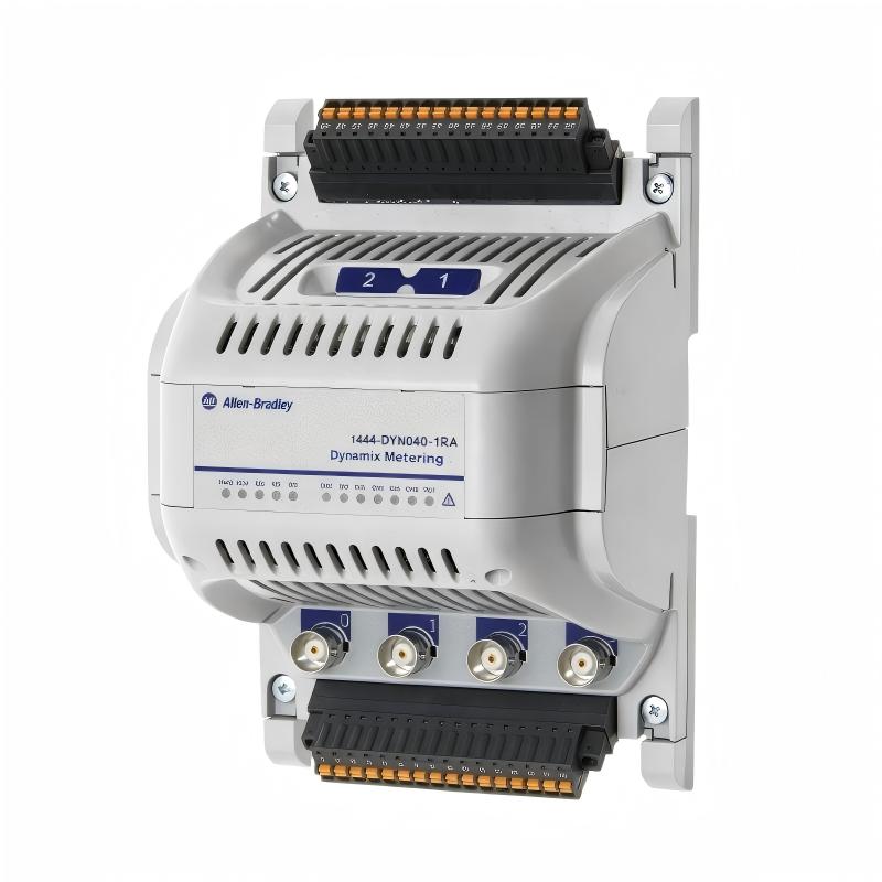
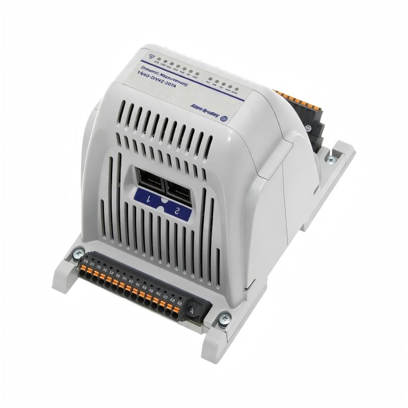
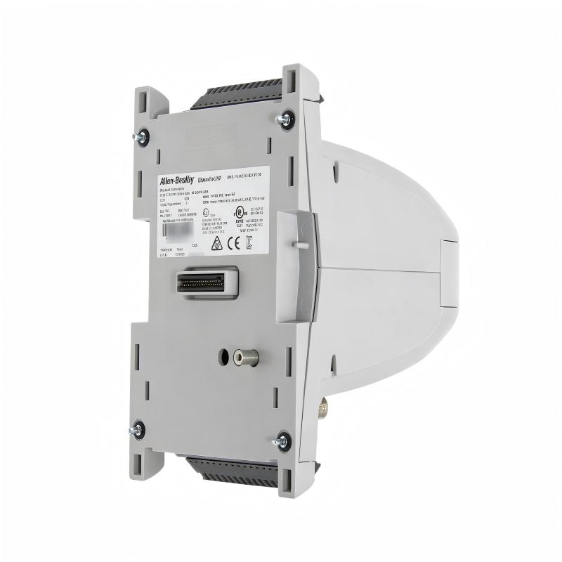
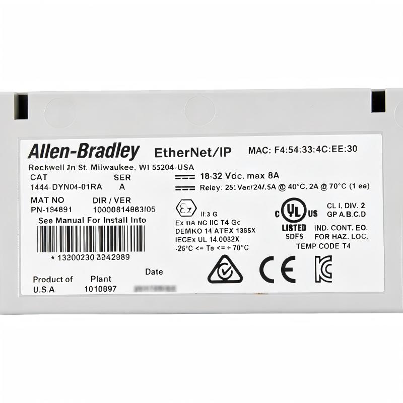
- Allen Bradley
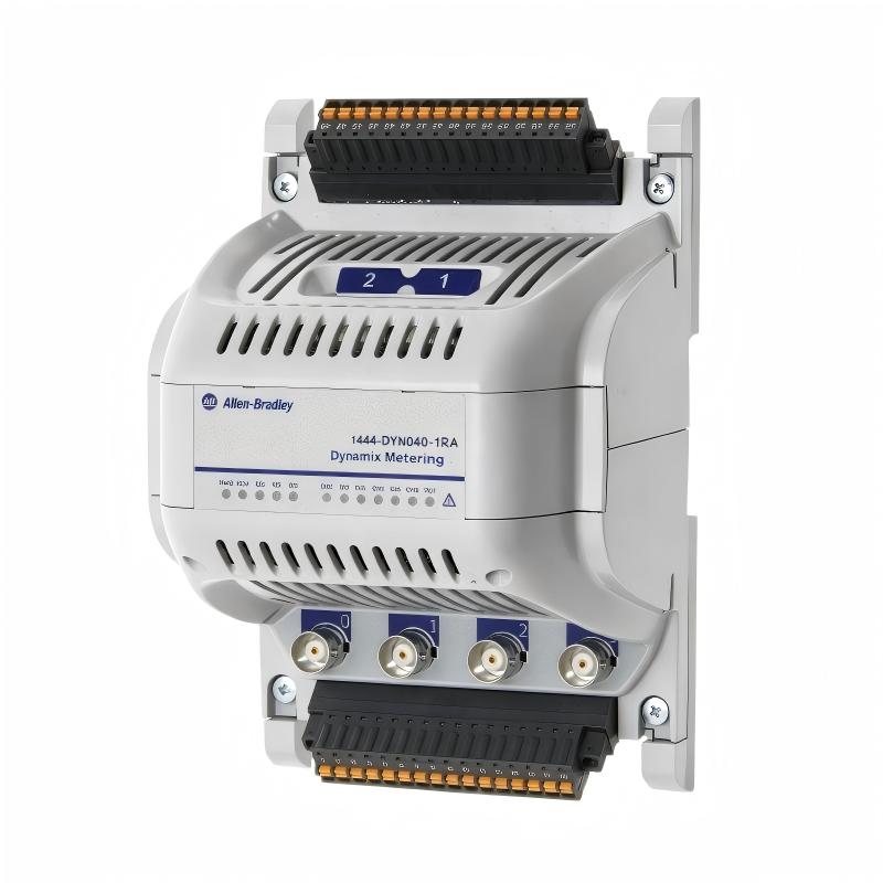
- 1444-DYN04-01RA
- Dynamic Measurement Module
- USA
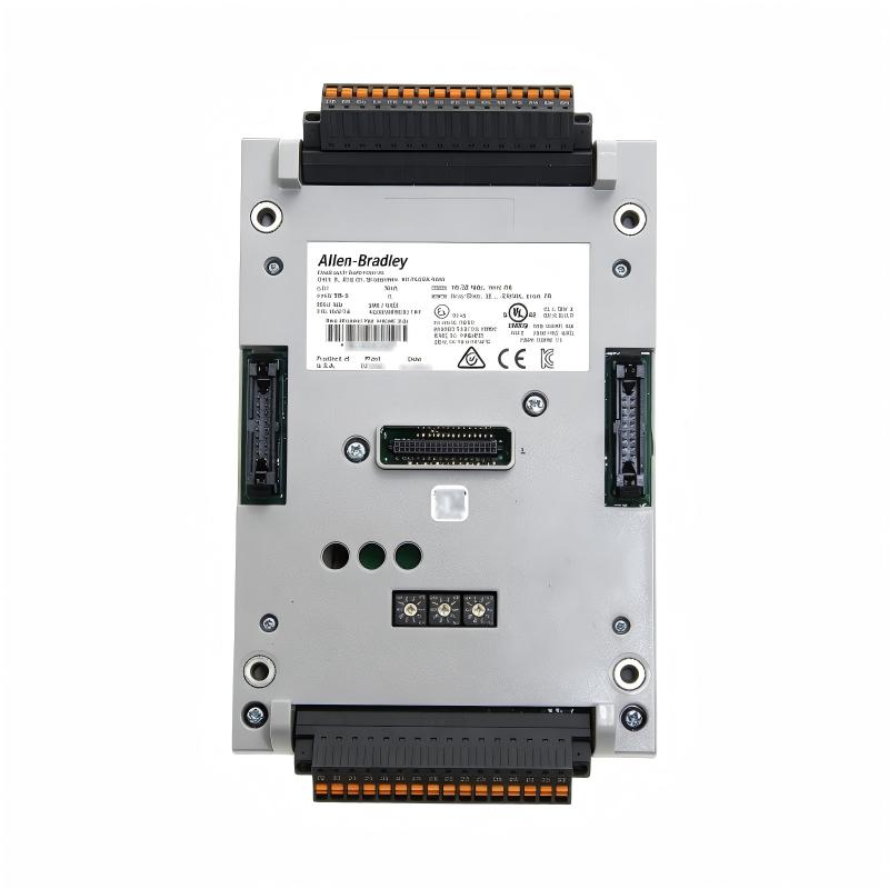
- 157.9 x 103.5 x 126.4 mm
- 0.592 kg
- Xiamen, China
- New & In Stock
- T/T, PayPal, Western Union
- 1 Year
- 1-3 Working Days
- DHL, UPS, TNT, FedEx and EMS.
- 24-Hour Service
- COO
- 5
Our advantage

Global Logistics
We have a 10-year logistics and express cooperation agreement, so our products can be shipped to any place in the world.

Brand new and original
Our products are imported in bulk from the place of origin. Because of the cooperative relationship, our products are all original and 100% new.

24-hour service
We provide 7*24 hours service to our customers. We will be there whenever you need us.

Price advantage
All our products are priced very favorably because we have our own warehouse and supply.
| Company Information | |||
| [email protected] | |||
| Mobile | +8615980777398 | ||
| +8615980777398 | |||
| 15980777398 |
1. Product Overview
The Allen-Bradley 1444-DYN04-01RA Dynamic Measurement Module is an industrial machinery monitoring device designed to measure dynamic and static operating parameters in rotating and reciprocating equipment. It belongs to the Allen-Bradley Dynamix 1444 series and supports condition monitoring applications that require detailed information about machine vibration, shaft movement, pressure fluctuations, and other mechanical operating conditions.
Unlike a standard PLC analog input module, the 1444-DYN04-01RA is specifically designed for machinery measurement and monitoring. It combines multiple measurement channels, signal conditioning, digital signal processing, data recording, alarm management, and industrial Ethernet communication in one modular device.
The module provides four measurement channels and two rotational speed inputs. Depending on the selected measurement mode, it can monitor dynamic signals such as shaft vibration, casing vibration, and pressure fluctuations, as well as static measurements such as shaft position, thrust, eccentricity, and rod drop. This flexibility makes it suitable for a variety of industrial machinery monitoring requirements.
The module supports integration with compatible Logix 5000 controllers through EtherNet/IP. Measurement data can be incorporated into a wider control and information architecture, allowing engineers to review machine operating conditions alongside other process variables.
The 1444-DYN04-01RA also supports waveform and Fast Fourier Transform (FFT) analysis, configurable measurement filtering, speed-related measurements, event logging, and data buffering. These capabilities help maintenance personnel investigate changes in machine behavior and identify conditions that may require further inspection.
For industrial plants that depend on rotating machinery, the module can form part of a condition monitoring strategy intended to improve equipment visibility, support maintenance planning, and reduce the risk of unexpected production interruptions.
The 1444-DYN04-01RA is a specialized measurement component rather than a standalone PLC or a complete machinery protection system. Its effectiveness depends on appropriate transducer selection, correct installation, suitable measurement configuration, and integration with the wider control and monitoring architecture.
2. Technical Specifications
| Parameter | Specification |
|---|---|
| Brand | Allen-Bradley |
| Product Series | Dynamix 1444 |
| Model Number | 1444-DYN04-01RA |
| Product Type | Dynamic Measurement Module |
| Number of Measurement Channels | 4 |
| Rotational Speed Inputs | 2 |
| Buffered Outputs | 4 |
| Communication Interface | EtherNet/IP |
| Ethernet Connections | 2 |
| Power Supply | 18–32 V DC |
| Power Supply Arrangement | Supports two supply inputs for redundant power arrangements |
| Typical Current Consumption | Approximately 411 mA at 24 V DC |
| Power Consumption | Approximately 11.5 W |
| Power Dissipation | Approximately 9 W |
| Control Relay | 1 SPDT relay |
| Expansion Relay Support | Compatible expansion relay arrangements, subject to system configuration |
| Analog-to-Digital Conversion | 24-bit |
| Typical Dynamic Range | Approximately 90 dB full scale |
| Sampling Capability | Up to 93 kS/s for two channels in the specified measurement mode |
| Supported Measurement Types | Dynamic vibration, pressure, position, thrust, eccentricity, rod drop, and other supported parameters |
| Signal Analysis | Time waveform, FFT, filtering, and supported speed-related analysis |
| Sensor Compatibility | Supported accelerometers, eddy-current probes, voltage signals, and other compatible transducers |
| Data Format | 32-bit floating point for supported measurement data |
| Configuration and Monitoring | Compatible Dynamix configuration tools and supported controller integration |
| Dimensions | 157.9 × 103.5 × 126.4 mm |
| Weight | 0.592 kg |
| Typical Applications | Machinery condition monitoring, vibration analysis, shaft position measurement, and equipment diagnostics |
Specification note: The dimensions and weight above are the values supplied for this product listing. Manufacturer documentation may state mechanical dimensions and weight for the module without its terminal base or associated installation hardware. Confirm the complete installed footprint, terminal base, wiring clearance, and power requirements before ordering or designing a replacement.
3. Function and Working Principle
3.1 Dynamic Signal Measurement
Dynamic signals change over time and can provide important information about the mechanical condition of industrial equipment. Examples include vibration generated by rotating shafts, pressure fluctuations in machinery, and oscillations associated with mechanical components.
The 1444-DYN04-01RA receives signals from compatible transducers and processes them through its measurement electronics. Engineers can configure measurement channels for the required sensor type, measurement range, filtering, and analysis method.
The resulting measurement data can be used to monitor operating trends, identify abnormal changes, and support further mechanical investigation.
For example, a vibration sensor installed on a motor bearing housing may detect changes in vibration amplitude as the motor operates. By comparing the measurement with established operating conditions, maintenance personnel can determine whether further inspection is necessary.
3.2 Four-Channel Measurement Architecture
The module provides four measurement channels, allowing engineers to monitor several machine locations or parameters within one device.
Possible measurement arrangements include:
- Vibration measurements at selected bearing locations
- Shaft displacement and position monitoring
- Dynamic pressure measurements
- Casing or pedestal vibration measurements
- Selected static measurements associated with machine movement
- Other supported mechanical parameters
The available channel combinations depend on the selected operating mode. Some modes allow all four channels to be configured for dynamic or static measurements, while other modes allocate specific channel pairs to different measurement functions.
In certain configurations, channels 0 and 1 can support higher-bandwidth dynamic measurement while channels 2 and 3 are used for static measurements. In a supported high-bandwidth mode, a channel pair can be configured for measurements up to 40 kHz or for gSE measurements, with the remaining channels disabled.
Consequently, engineers should choose the measurement mode according to the required bandwidth, number of active channels, and machine monitoring objectives rather than assuming that every channel can operate at the maximum bandwidth simultaneously.
3.3 Signal Conditioning and Filtering
Industrial transducer signals may contain useful vibration information as well as unwanted electrical noise, mechanical interference, or frequency components outside the range of interest.
The module supports configurable filtering and signal conditioning to help isolate relevant measurement information. Depending on the measurement type and configuration, engineers can select high-pass and low-pass filtering, integration, and other supported signal-processing functions.
Integration can be useful when converting acceleration measurements into velocity or displacement-related measurements, provided the sensor type, frequency range, and configuration are appropriate.
Filter settings must be selected carefully. An unsuitable cutoff frequency or integration setting can suppress useful signal components or distort the measurement. The configuration should therefore reflect the physical characteristics of the machinery and the diagnostic objectives.
3.4 Time Waveform and FFT Analysis
Time waveform analysis displays how a measured signal changes over time. It can help engineers examine transient events, periodic vibration, impacts, and unusual operating behavior.
Fast Fourier Transform analysis converts a time-domain signal into frequency-domain information. This helps identify dominant frequencies and examine how different frequency components contribute to the measured signal.
For rotating machinery, frequency-domain analysis may help investigate imbalance, misalignment, mechanical looseness, and other vibration-related conditions. The results must be interpreted in context because similar patterns can arise from different mechanical causes.
The 1444-DYN04-01RA supports configurable FFT windows and measurement settings. Correct selection of the sampling rate, measurement bandwidth, filter settings, and analysis window is important for obtaining meaningful results.
3.5 Rotational Speed and Order-Related Measurements
The module provides two rotational speed inputs for compatible tachometer signals. Speed information is important because many mechanical vibration components are directly or indirectly related to shaft rotational speed.
When suitable speed signals and measurement configurations are available, engineers can evaluate vibration components in relation to shaft rotation. This can help distinguish speed-related vibration patterns from other frequency components.
Speed inputs may also support measurement synchronization and selected tracking or order-domain analysis functions. Accurate tachometer installation, correct pulse configuration, and appropriate synchronization settings are essential for reliable results.
3.6 Static Measurement Capability
Although the product is called a Dynamic Measurement Module, it also supports selected static measurement functions.
Depending on the transducer and configured mode, these measurements may include shaft position, thrust, eccentricity, and rod drop. Such parameters can be important in monitoring reciprocating machinery, large rotating equipment, and other installations where mechanical displacement must be observed.
The supported measurement type depends on the sensor, channel configuration, and application requirements. Engineers should confirm the compatibility of each measurement with the intended transducer and hardware setup.
3.7 Data Buffering and Event Logging
The module supports data buffering and event logging to help preserve information about machine behavior and significant events.
Its documented buffering capabilities include multiple buffers for discrete and dynamic records. Dynamic records can contain waveform and FFT information, while supported trigger conditions can capture data around selected operating events.
The system also supports event logging for categories such as system events, alarms, and buffer activity. Time-stamped records can assist maintenance teams in correlating measurement changes with operating events.
Buffer configuration should account for the required recording frequency, trigger conditions, available storage capacity, and the type of data needed for troubleshooting.
3.8 EtherNet/IP Communication
The 1444-DYN04-01RA uses EtherNet/IP to integrate with compatible industrial controllers and monitoring systems. Its Ethernet interfaces provide the communication path for configured measurement and status data.
When integrated into a suitable Logix 5000 control architecture, measurement information can be incorporated into controller logic, operator displays, and plant-level monitoring applications.
Network configuration, controller compatibility, data mapping, and software support should be verified before commissioning. Ethernet connectivity alone does not guarantee that every measurement parameter is automatically available to every connected controller.
4. Role in Industrial Control Systems
4.1 Machinery Condition Monitoring
The module provides dedicated measurement capability for monitoring the mechanical condition of industrial equipment.
By measuring vibration, shaft position, pressure, and other supported parameters, it can help maintenance personnel establish baseline conditions and recognize changes that warrant investigation.
Condition monitoring is most effective when measurements are collected consistently and evaluated alongside machine speed, operating load, process conditions, and maintenance history.
4.2 Integration with Logix 5000 Controllers
The Dynamix 1444 series is designed to integrate with compatible Logix 5000 controllers over industrial Ethernet.
This allows measurement data to be incorporated into a broader automation architecture. Depending on the controller configuration and application, the system may display machine condition values, report alarms, store selected measurements, and coordinate maintenance-related responses.
The module remains a dedicated measurement device. Controller programming and configuration are needed to determine how measurement values and status information are used by the wider automation system.
4.3 Supporting Machinery Diagnostics
Machine vibration and position measurements can provide early indications of mechanical changes.
For example, an increase in vibration may prompt an inspection of a bearing, coupling, mounting arrangement, or rotating assembly. A change in shaft position may indicate that the machine’s mechanical behavior requires further evaluation.
The module supplies measurement information; it does not independently guarantee the identification of every fault. Diagnosis depends on the measurement setup, machine characteristics, and appropriate engineering interpretation.
4.4 Alarm and Relay Integration
The module includes a control relay and supports compatible expansion relay arrangements. These outputs can be used for selected alarm or status functions where supported by the configured monitoring system.
Engineers can define how supported alarm conditions are presented to external equipment, subject to the available relay functions and application design.
For high-consequence machinery protection, the complete system must be evaluated against applicable protection and safety requirements. A measurement module and its relay outputs should not automatically be treated as a substitute for a dedicated certified protection system.
4.5 Improving Maintenance Visibility
When measurement trends and event records are available, maintenance teams can review how a machine behaved before, during, and after an operating event.
This information can help prioritize inspections, verify maintenance work, and improve the quality of troubleshooting records. It can also provide useful evidence when comparing machine behavior across operating conditions.
5. Typical Industrial Applications
5.1 Electric Motors and Motor-Driven Equipment
Electric motors are widely used throughout manufacturing and process industries. Vibration monitoring can help detect changes associated with imbalance, misalignment, bearing deterioration, and mounting problems.
The 1444-DYN04-01RA can monitor selected vibration channels and provide measurement information to a compatible control system. Sensor placement should be selected according to the motor design, bearing locations, operating speed, and monitoring objective.
5.2 Pumps and Pumping Systems
Pumps can experience vibration changes caused by mechanical wear, bearing issues, alignment problems, hydraulic conditions, or changes in operating load.
By monitoring vibration and other supported parameters, the module can help maintenance personnel recognize changes that warrant investigation. Vibration data should be reviewed alongside process variables such as pressure, flow, temperature, and pump operating state.
5.3 Fans and Blowers
Industrial fans and blowers may operate continuously in production, ventilation, and utility systems. Imbalance, loose mounting, bearing problems, and changes in rotating components can affect vibration behavior.
The module can provide configured vibration measurements from selected fan or blower locations. Trends can help maintenance teams decide when cleaning, balancing, mechanical inspection, or bearing replacement should be considered.
5.4 Compressors
Compressors may contain high-speed rotating components or reciprocating mechanisms that require careful monitoring.
The 1444-DYN04-01RA supports several measurement types that may be relevant to compressor applications, including dynamic vibration and selected static parameters. The actual suitability depends on the compressor type, sensor arrangement, measurement bandwidth, and required monitoring functions.
Critical compressor applications may require additional protection devices and independent safety systems.
5.5 Turbines and Large Rotating Machinery
Large rotating machinery may require multiple vibration and shaft-position measurements. These values can help engineers understand machine behavior during startup, steady-state operation, load changes, and shutdown.
The module’s multi-channel architecture, speed inputs, and signal-analysis capabilities can support selected monitoring applications when the configuration is appropriate for the machine.
The required measurement ranges, sensor compatibility, and protection requirements should be established before system design.
5.6 Reciprocating Machinery
Reciprocating equipment can experience mechanical movement and vibration patterns that differ from those of continuously rotating machinery.
The module supports selected measurements such as rod drop and other compatible static or dynamic parameters. Such measurements may be useful when evaluating the mechanical condition of reciprocating equipment, provided that the transducers and channel configuration are appropriate.
5.7 Industrial Process and Utility Equipment
The module can also be used in selected process and utility applications where dynamic pressure, vibration, position, or other supported measurements are required.
Examples may include industrial machinery in water treatment, material processing, energy production, and manufacturing facilities. The final configuration should reflect the operating environment, monitoring objectives, and required integration with the plant control system.
6. Installation and System Integration
Correct installation is essential for accurate measurement and stable communication. Sensor selection, signal wiring, power supply, grounding, network configuration, and software setup all influence system performance.
6.1 Verify the Complete Catalog Number
Before installation or replacement, confirm the complete catalog number 1444-DYN04-01RA.
Check the installed hardware revision, controller platform, firmware requirements, compatible terminal base, and supported configuration software. Do not assume that all modules in the Dynamix 1444 series have identical functions or wiring requirements.
6.2 Confirm the Mechanical Installation
The module is designed for installation within the specified Dynamix system arrangement. Verify the terminal base, DIN rail or panel mounting, enclosure requirements, wiring clearance, and the total installed dimensions.
The dimensions and weight in the product listing should be distinguished from any dimensions specified for the module without its terminal base or associated installation hardware.
Allow sufficient space for wiring, ventilation, maintenance access, and Ethernet cable routing. The module should be installed in an enclosure appropriate for the operating environment because the module itself is an open-style device.
6.3 Select Compatible Transducers
The module supports several signal types, including compatible accelerometers, eddy-current probe systems, voltage signals, and other supported transducers.
Before connecting a sensor, confirm:
- Sensor type and measurement purpose
- Sensitivity and signal range
- Required positive or negative transducer supply
- Input polarity and wiring arrangement
- Cable type and shielding
- Sensor mounting location
- Applicable channel and measurement mode
- Required frequency range and filtering
A sensor that produces a compatible electrical signal may still be unsuitable for a particular measurement if its bandwidth, sensitivity, or physical installation does not meet the application requirements.
6.4 Configure Measurement Channels
Choose the channel mode according to the number of sensors and the required measurement bandwidth.
Depending on the selected mode, channels may support combinations of dynamic and static measurements or higher-bandwidth operation on selected channels. Not every channel arrangement supports every measurement type simultaneously.
Configure the engineering units, signal range, filter settings, integration, and other measurement parameters according to the sensor and monitoring objective. Document each channel’s purpose to avoid confusion during maintenance.
6.5 Connect the Speed Inputs
If speed-synchronized measurements or order-related analysis are required, connect compatible tachometer signals to the appropriate speed inputs.
Verify the signal type, pulse arrangement, wiring, and speed configuration. Confirm that the controller and module configuration use the intended speed source.
Incorrect tachometer configuration can result in inaccurate speed measurements and unreliable synchronization of vibration data.
6.6 Connect the DC Power Supply
The module supports an 18–32 V DC supply arrangement and provides for redundant power inputs where required by the system design.
Verify that the power supplies meet the module requirements, that polarity and terminal connections are correct, and that the available current capacity is sufficient for the installation.
If redundant supplies are used, check their wiring and behavior according to the system documentation. Follow approved electrical isolation procedures before installing or removing the module.
6.7 Configure EtherNet/IP Communication
Connect the module to the intended industrial Ethernet network and configure the communication parameters according to the controller and system requirements.
Check the IP configuration, controller compatibility, network topology, cable selection, and supported data mapping. Where a redundant or resilient Ethernet architecture is required, verify the applicable network design and supported configuration.
Confirm that the controller can communicate with the module and access the intended measurement and status data before proceeding with full commissioning.
6.8 Configure Alarms and Relay Functions
Configure measurement thresholds and supported alarm functions according to the machinery requirements and the host system’s capabilities.
If the control relay or an expansion relay module is used, document the expected contact state during normal operation, alarm conditions, and power loss. Confirm that external wiring matches the intended logic.
Alarm thresholds should be established using engineering criteria and appropriate machine baselines rather than arbitrary values.
6.9 Verify Data Recording and Diagnostics
Configure the data buffers and event logging functions according to the required troubleshooting and monitoring objectives.
If waveform or FFT capture is required, verify the trigger conditions, record intervals, channel assignments, and available buffer capacity. Check that time-stamped events can be retrieved and interpreted using the intended tools.
Before returning equipment to service, test the configured measurements, controller communication, alarms, and external interfaces under controlled conditions.
7. Compatible System Components
The 1444-DYN04-01RA operates as part of a broader Dynamix machinery monitoring system. The following components may be relevant, depending on the installation.
| Component | Function |
|---|---|
| Allen-Bradley 1444-DYN04-01RA | Provides four-channel dynamic and static measurement capabilities |
| Compatible terminal base | Provides the specified module mounting and electrical connections |
| Compatible Logix 5000 controller | Integrates supported measurement and status information into the control application |
| Industrial Ethernet switch | Connects the module to the appropriate EtherNet/IP network |
| Compatible accelerometers | Provide vibration measurement signals |
| Eddy-current probe system | Supports selected shaft displacement and position measurements |
| Compatible pressure transducer | Provides dynamic pressure signals where supported |
| Tachometer or speed sensor | Supplies rotational speed information |
| 18–32 V DC power supply | Provides the required module supply |
| Redundant DC supply arrangement | Supports higher availability when configured appropriately |
| PLC digital input module | Receives external relay status where used |
| Compatible expansion relay module | Provides additional relay outputs when supported |
| Industrial HMI or monitoring software | Displays measurements, status, and alarms |
| Engineering workstation | Supports configuration, diagnostics, and maintenance activities |
Compatibility should be verified for the exact hardware revision, sensor type, controller firmware, software version, and system configuration. The presence of an Ethernet connection does not guarantee compatibility with every controller or software package.
8. Alternative Models and Replacement Considerations
The 1444-DYN04-01RA provides a particular combination of measurement channels, speed inputs, signal-processing functions, and EtherNet/IP communication. A replacement must match the actual monitoring requirements rather than simply provide a similar number of inputs.
| Replacement Approach | Key Considerations |
|---|---|
| Another 1444-DYN04-01RA module | Confirm catalog number, hardware revision, condition, firmware, and configuration compatibility |
| Another Dynamix 1444 series module | Check channel count, measurement bandwidth, sensor support, speed inputs, and communication features |
| A different machinery monitoring module | Verify measurement types, signal conditioning, data recording, alarm functions, and controller integration |
| A modern condition monitoring platform | Evaluate sensor reuse, network architecture, software migration, data mapping, protection requirements, and downtime |
A different module may support conventional vibration monitoring but lack a required measurement type, bandwidth, or data-processing function. It should not be considered a direct replacement until these differences have been assessed.
Before purchasing, record the complete catalog number, hardware revision, terminal base, firmware, controller model, sensor types, channel configuration, speed input assignments, and network settings. Preserve the existing configuration and relevant project documentation wherever possible.
For used or refurbished modules, verify the condition of the connectors, terminals, and housing. Ask the supplier about functional testing, warranty coverage, return terms, and availability before placing an order.
After replacing a module, verify each measurement channel, speed input, data stream, alarm configuration, and external interface. The system should be tested before being returned to normal operation.
9. Key Advantages of the 1444-DYN04-01RA
Four-Channel Measurement Capability
The module supports monitoring of several machine parameters or measurement locations within one device, subject to the selected measurement mode.
Flexible Dynamic and Static Measurements
Its supported measurement functions cover vibration, pressure, shaft position, and other selected mechanical parameters. This allows one module type to support different monitoring requirements.
Advanced Signal Processing
Waveform analysis, FFT, filtering, and other supported processing functions provide information that can help engineers investigate changes in machine behavior.
Speed-Related Monitoring
Two speed inputs support rotational speed measurements and selected synchronized analysis functions when the sensor arrangement and configuration are appropriate.
EtherNet/IP Integration
The communication interface enables integration with compatible Logix 5000 control systems and wider industrial Ethernet architectures.
Data Buffering and Event Logging
Configurable recording and event logging can preserve useful information about operating conditions and help maintenance personnel investigate machine events.
Redundant Power Capability
The module supports a dual-input power arrangement for applications requiring redundant DC supply design, subject to the applicable system configuration.
Industrial Machinery Applications
The module can be applied to selected motors, pumps, compressors, turbines, reciprocating equipment, and other machinery when the sensors and measurement configuration meet the application’s requirements.
10. Frequently Asked Questions
Q1. What is the Allen-Bradley 1444-DYN04-01RA?
It is a Dynamix 1444 Dynamic Measurement Module designed for industrial machinery condition monitoring. It measures supported dynamic and static signals and communicates measurement information through EtherNet/IP.
Q2. How many measurement channels does it have?
The module provides four measurement channels. The available combinations and maximum bandwidth depend on the selected operating mode.
Q3. Which communication protocol does it use?
The module uses EtherNet/IP and is designed for integration with compatible Logix 5000 controllers and industrial Ethernet systems.
Q4. What measurements can it support?
Depending on the sensor and configuration, supported measurements include vibration, dynamic pressure, shaft position, thrust, eccentricity, rod drop, and other mechanical parameters.
Q5. Does it support FFT and waveform analysis?
Yes. The module supports time waveform and FFT-related functions, along with configurable signal-processing options. These features help engineers examine vibration signals and investigate abnormal machine behavior.
Q6. How many speed inputs are available?
The module has two rotational speed inputs for compatible tachometer signals. These inputs can support speed-related and selected synchronized measurement functions.
Q7. What power supply is required?
The specified supply range is 18–32 V DC. The module supports two supply inputs for redundant power arrangements when required by the installation.
Q8. Does the module have relay outputs?
The module includes one SPDT control relay and supports compatible relay expansion arrangements. Verify the required contact rating and supported relay configuration before using it in an alarm or control circuit.
Q9. Can it directly replace any vibration monitoring module?
No. Different modules can have different sensor interfaces, channel modes, measurement bandwidths, data processing, communication features, and relay functions. A replacement must meet the requirements of the existing application.
Q10. Why might a measurement channel show an incorrect value?
Possible causes include an incompatible sensor, incorrect sensitivity settings, wiring problems, grounding issues, unsuitable filter settings, an incorrect measurement mode, or sensor mounting problems. Check the configuration and physical signal path before replacing the module.
Q11. What should be checked before purchasing a replacement?
Confirm the full catalog number, hardware revision, terminal base, controller compatibility, firmware, sensor requirements, channel configuration, speed inputs, and communication settings. Verify the actual installed dimensions and weight if these are important for the replacement.
Q12. Is the 1444-DYN04-01RA a complete machinery protection system?
No. It is a measurement module that can contribute to condition monitoring and supported alarm functions. Whether the complete installation meets machinery protection requirements depends on the full system design, configured functions, external equipment, and applicable standards.
11. Procurement and Maintenance Recommendations
When purchasing the Allen-Bradley 1444-DYN04-01RA, the most important step is to confirm that the module matches the measurement and communication requirements of the existing installation.
Consider the following checks before placing an order:
- Catalog number: Confirm that the required part is 1444-DYN04-01RA.
- Hardware revision: Check the installed revision and any firmware or configuration requirements.
- Mechanical fit: Verify the complete installed dimensions, terminal base, mounting arrangement, and wiring clearance.
- Sensor compatibility: Confirm the sensor type, signal range, sensitivity, and required transducer power.
- Channel configuration: Record the active measurement mode, bandwidth, filters, and engineering units.
- Speed configuration: Document tachometer wiring, speed source assignments, and synchronized measurement settings.
- Network compatibility: Verify EtherNet/IP settings, controller compatibility, and data mapping.
- Power arrangement: Confirm the DC supply range and whether redundant power inputs are required.
- Condition and warranty: For surplus or refurbished units, review test results, warranty terms, and return conditions.
- Configuration backup: Keep the configuration files, controller project, channel assignments, and commissioning records.
During routine maintenance, inspect the sensor wiring, connectors, terminal base, grounding, and power supply. Review measurement trends and event logs to identify changes that may require further investigation.
If the module reports unexpected values or communication faults, check the sensor signal, channel configuration, power status, Ethernet connection, and controller data mapping before assuming that the module has failed.
After replacement or reconfiguration, verify all required channels, speed measurements, alarms, data recording, and controller communication. Document the results so that future maintenance work can be completed more efficiently.
12. Conclusion
The Allen-Bradley 1444-DYN04-01RA Dynamic Measurement Module is a specialized machinery monitoring device that combines four measurement channels, two speed inputs, signal processing, data buffering, and EtherNet/IP communication.
Its support for dynamic vibration and pressure signals, selected static measurements, waveform and FFT analysis, and speed-related monitoring makes it suitable for a variety of industrial machinery condition monitoring applications.
For maintenance engineers, system integrators, and industrial spare-parts purchasers, selecting the correct hardware revision and verifying sensor compatibility, measurement configuration, controller integration, and installation requirements are essential steps.
When properly installed and configured, the 1444-DYN04-01RA can provide useful measurement data for machinery diagnostics, condition monitoring, and maintenance planning within a compatible industrial automation system.