

ProductPRODUCT
Featured products
Contact Us
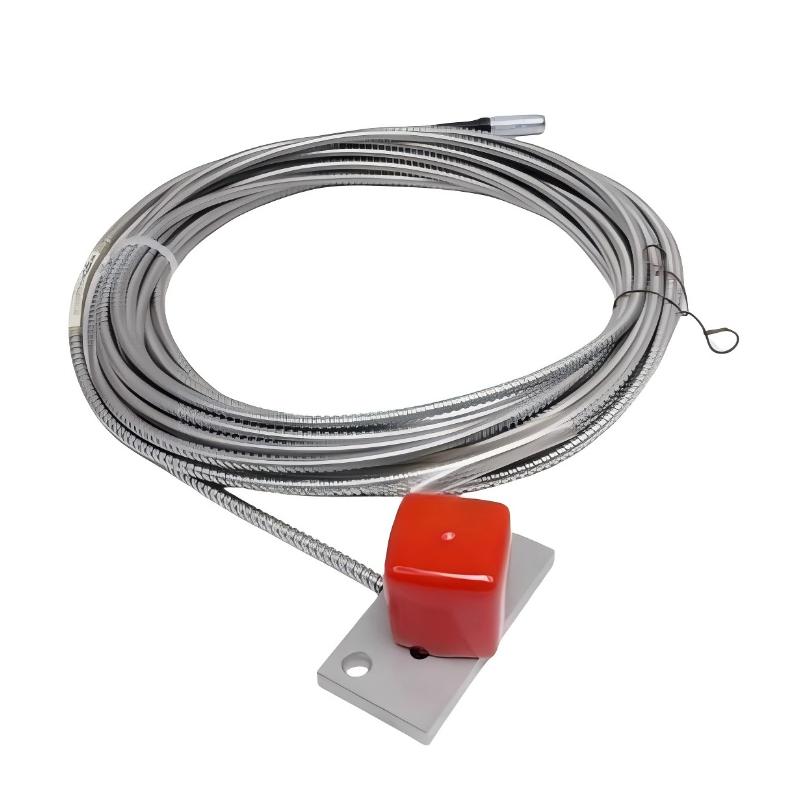
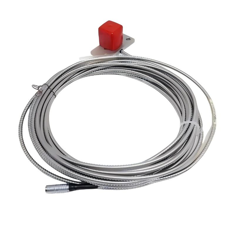
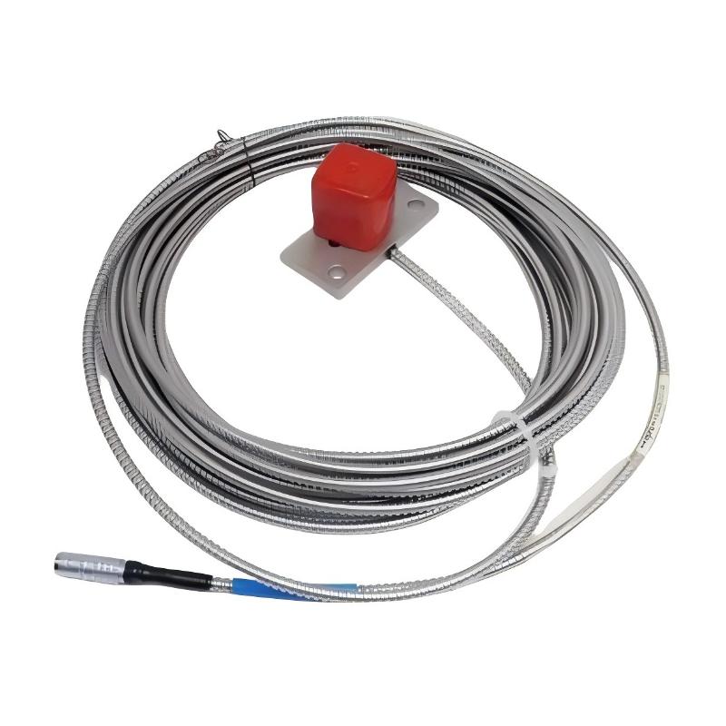
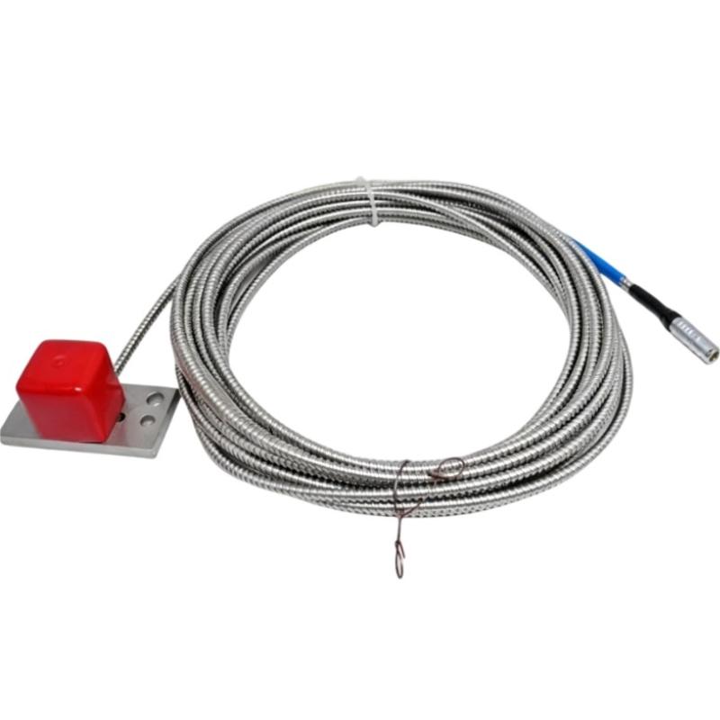
- Epro
- PR6426/010-010
- 32 mm Eddy Current Sensor
- Germany
- 32 mm
- 0.8 kg
- Xiamen, China
- New & In Stock
- T/T, PayPal, Western Union
- 1 Year
- 1-3 Working Days
- DHL, UPS, TNT, FedEx and EMS.
- 24-Hour Service
- COO
- 8
Our advantage

Global Logistics
We have a 10-year logistics and express cooperation agreement, so our products can be shipped to any place in the world.

Brand new and original
Our products are imported in bulk from the place of origin. Because of the cooperative relationship, our products are all original and 100% new.

24-hour service
We provide 7*24 hours service to our customers. We will be there whenever you need us.

Price advantage
All our products are priced very favorably because we have our own warehouse and supply.
| Company Information | |||
| [email protected] | |||
| Mobile | +8615980777398 | ||
| +8615980777398 | |||
| 15980777398 |
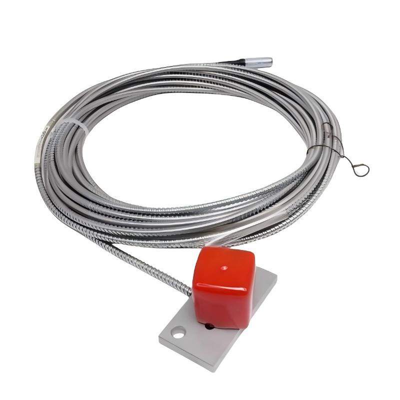
Product Overview
The Epro PR6426/010-010 is a 32 mm eddy current sensor used for non-contact displacement measurement in rotating machinery. Its application centers on monitoring the relative position of a conductive shaft surface, particularly in equipment where continuous shaft movement measurements are needed for operational assessment and machinery protection.
In a turbine installation, a displacement sensor mounted near a bearing can measure changes in shaft position relative to the stationary machine structure. On a large compressor, similar measurements help engineers investigate rotor movement during startup, changes in operating load, or an unexpected change in vibration behavior. The sensor can also be used in compatible monitoring arrangements for pumps, fans, and other rotating equipment.
The PR6426/010-010 operates as the sensing element in a complete measuring chain. It detects changes in the electromagnetic interaction between its sensing head and the conductive target. A compatible signal converter supplies the excitation and processes the sensor response into an electrical signal that can be interpreted by monitoring equipment.
The /010-010 designation should be retained when identifying this sensor for installation or replacement. Other PR6426 variants may share the same nominal head diameter while differing in cable termination, connection arrangement, or other ordering details. A replacement decision therefore requires more than matching the series name.
The sensor’s practical performance also depends on how it is installed. Target material, mounting rigidity, initial gap, converter compatibility, and the receiving channel’s calibration all influence the measurement. These factors should be considered together when adding the sensor to an existing machinery monitoring system.
Technical Specifications
| Parameter | Specification |
|---|---|
| Manufacturer | Epro |
| Model | PR6426/010-010 |
| Product Type | 32 mm Eddy Current Sensor |
| Measurement Principle | Non-contact eddy current |
| Sensor Head Diameter | 32 mm |
| Weight | 0.8 kg |
Product Features
- Non-contact displacement sensing: Measures changes in the distance between the sensor and a conductive target without mechanical contact with the rotating shaft.
- 32 mm sensor-head configuration: Intended for the PR6426 installation arrangement. Mounting clearance and the surrounding target geometry should be checked before installation.
- Suitable for rotating-machinery monitoring: Provides shaft-displacement information that can be evaluated alongside vibration, speed, and operating-condition data.
- Converter-based measurement: Operates with compatible signal-conditioning equipment rather than functioning as a standalone displacement display.
- Variant-specific identification: The complete
/010-010ordering code helps distinguish this sensor from other PR6426 configurations during maintenance and spare-parts selection. - Integration with monitoring channels: Its conditioned measurement can be incorporated into a compatible system for displaying readings, recording trends, and evaluating configured limits.
- Installation-dependent performance: Correct target alignment, mounting rigidity, cable condition, and measuring-chain calibration are necessary for meaningful readings.
Working Principle
The PR6426/010-010 measures displacement through electromagnetic coupling between its sensing coil and a conductive target. When the compatible converter excites the sensor, an alternating electromagnetic field forms at the sensing head. This field induces eddy currents in the target, changing the electrical response of the sensor.
As the shaft moves relative to the stationary probe, the distance between the sensor and target changes. The resulting change in electromagnetic coupling is processed by the converter and translated into an electrical signal corresponding to the target’s position within the calibrated measuring range.
The basic measurement path is:
Conductive Shaft Target → PR6426/010-010 Sensor → Compatible Signal Converter → Monitoring System
The sensor measures relative movement rather than diagnosing a mechanical fault by itself. For example, a change in shaft displacement during compressor startup may reflect normal thermal or operating movement, while an unexpected change during steady operation may require further investigation. The meaning of the reading depends on the machine’s operating state and the monitoring limits established for that installation.
The initial gap between the sensor head and the target determines the measurement operating point. If the probe is positioned incorrectly, the available measurement travel may be insufficient in one direction, or the signal may operate outside the intended linear region. The correct gap must therefore be established using the applicable sensor and converter instructions.
Target material is another consideration. Eddy current response depends on the electrical and magnetic properties of the measured surface. If the shaft material differs from the material used for the measuring chain’s calibration, the effect on measurement characteristics must be evaluated.
Role in the Machinery Monitoring Architecture
The PR6426/010-010 occupies the sensing stage of a shaft-displacement measurement channel. It detects relative movement at the machine and supplies the sensor response to compatible signal-conditioning equipment. The converter and monitoring system then make the measurement available for operational assessment.
| System Element | Function |
|---|---|
| PR6426/010-010 Sensor | Detects relative displacement between the sensing head and the target |
| Rotating Shaft | Provides the conductive target surface |
| Sensor Mounting Assembly | Maintains the sensor’s position relative to the machine |
| Sensor Cable and Connection | Carries the sensor connection to the compatible converter |
| Signal Converter | Excites the sensor and conditions its response |
| Monitoring Input | Receives and scales the conditioned measurement signal |
| Machinery Monitoring System | Displays measurements, records trends, and evaluates configured limits |
| Plant Diagnostic Interface | Presents monitoring information to operators and maintenance personnel |
In a turbine, a displacement channel can be used to observe shaft movement near a bearing location. In a compressor, the sensor reading may be compared with vibration, speed, and process data to help engineers investigate changes in rotor behavior.
The sensor and converter must be treated as a matched measurement chain. A replacement sensor should be checked against the installed converter and the receiving system’s calibration before its readings are compared with historical data.
Industrial Applications
| Application | Practical Use |
|---|---|
| Steam Turbines | Monitoring shaft-position changes during startup and normal operation |
| Gas Turbines | Measuring relative movement within critical rotating assemblies |
| Hydro Turbines | Observing shaft displacement in large turbine machinery |
| Industrial Compressors | Supplying displacement data for rotor-condition assessment |
| Centrifugal Pumps | Measuring relative shaft movement in compatible monitoring arrangements |
| Industrial Fans | Tracking shaft-position changes during operation |
| Power Generation Plants | Supporting displacement monitoring of rotating machinery |
| Petrochemical Facilities | Providing shaft-displacement information for critical process equipment |
| Machinery Overhauls | Replacing a sensor after checking the existing mounting and connection configuration |
| Predictive Maintenance | Comparing displacement trends with vibration and operating data |
Installation and Maintenance
- Verify the complete model designation: Confirm PR6426/010-010 against the installed sensor marking and maintenance records. Do not select a replacement based only on the PR6426 family name.
- Check converter compatibility: Verify that the existing signal converter supports the sensor and the intended measurement configuration. Confirm calibration compatibility before connecting the sensor.
- Inspect the target surface: Check the shaft measurement area for damage, deposits, or surface conditions that may affect the measurement. Confirm that the target material is appropriate for the existing calibration.
- Prepare the mounting location: Inspect the bracket, mounting threads, and fixing points. The sensor must remain stationary relative to the machine structure during operation.
- Set the initial gap: Adjust the sensor-to-target distance according to the applicable installation procedure for the sensor and converter combination. Do not guess the gap from the head diameter alone.
- Check the surrounding clearance: Inspect nearby metallic components that could affect the electromagnetic field. Confirm that the mounting arrangement provides the required clearance around the sensing area.
- Inspect the sensing head: Look for deformation, impact damage, or contamination before installation. Replace damaged mounting hardware rather than using it to compensate for a poorly aligned sensor.
- Examine the cable condition: Check for cuts, crushing, abrasion, and excessive bending. Route the cable away from moving components and heat sources beyond its applicable temperature limits.
- Verify the connection arrangement: Confirm that the cable termination and connector match the receiving converter. Do not assume that all PR6426 variants use identical connections.
- Check the electrical signal: After installation, follow the approved commissioning procedure to confirm that the converter receives the sensor signal and produces the expected response as the target position changes.
- Validate the monitoring channel: Check the receiving system’s scaling, engineering units, and configured limits. Compare the reading with expected machine behavior before returning the channel to normal service.
- Record installation details: Document the complete model number, converter identification, initial gap, connection arrangement, and commissioning results. These records help maintain consistency during future inspection and replacement.
Compatible System Components
| Component | Function |
|---|---|
| Compatible CON021 Signal Converter | Excites the sensor and conditions its response for measurement |
| Compatible CON031 Signal Converter | Provides an alternative converter family where the specific sensor and configuration are supported |
| Machinery Monitoring Input | Receives the conditioned displacement signal |
| Compatible Monitoring Module | Processes the measurement for display, trending, or alarm evaluation |
| Sensor Mounting Hardware | Maintains the probe’s position relative to the target |
| Matching Cable and Connector Assembly | Connects the sensor to the specified measuring electronics |
| Control Cabinet Power Supply | Supplies the converter within its specified electrical requirements |
| Conductive Shaft Target | Provides the surface used for eddy current displacement measurement |
Compatibility must be confirmed for the actual sensor configuration and measuring chain. The presence of the same PR6426 family designation does not establish that every converter or cable assembly is interchangeable.
Recommended Related Models
| Model | Product Type | Selection Consideration |
|---|---|---|
| Epro PR6426/010-000 | 32 mm Eddy Current Sensor | Compare the ordering code and connection configuration with the installed sensor |
| Epro PR6426/010-100 | 32 mm Eddy Current Sensor | Verify the complete variant designation before considering replacement |
| Epro PR6426/010-110 | 32 mm Eddy Current Sensor | Check the connection and measuring-chain requirements against the application |
| Epro PR6426/010-130 | 32 mm Eddy Current Sensor | Confirm the exact configuration and converter compatibility |
| Epro PR6426/010-140 | 32 mm Eddy Current Sensor | Compare the full ordering code and installation arrangement before substitution |
Key Advantages
- Non-contact measurement of relative shaft displacement.
- 32 mm sensor-head configuration for compatible PR6426 installations.
- Integration with compatible signal converters and machinery monitoring equipment.
- Useful displacement data for rotating-machinery condition assessment.
- Variant-specific identification for maintenance and replacement planning.
Technical FAQs
What should be verified before replacing a PR6426/010-010 with another PR6426 model?
Check the complete ordering code, cable termination, connector arrangement, mounting requirements, and compatibility with the installed converter. A shared series name and head diameter are not enough to establish direct interchangeability.
Can the PR6426/010-010 be connected directly to a PLC analog input?
The sensor should not be assumed to provide a directly compatible PLC signal on its own. The measuring chain normally requires compatible signal-conditioning equipment, and the converter output must match the PLC input’s electrical range and scaling.
Why can shaft-displacement readings change after sensor replacement?
A different initial gap, connection arrangement, target material, or converter calibration can change the measurement response. The installation and measuring chain should be checked before interpreting the change as actual machine movement.
What information should be retained after commissioning?
Record the complete sensor model, converter designation, mounting gap, connection details, monitoring-channel scaling, and commissioning readings. This information helps maintenance personnel reproduce the intended configuration during future replacement work.