

ProductPRODUCT
Featured products
Contact Us
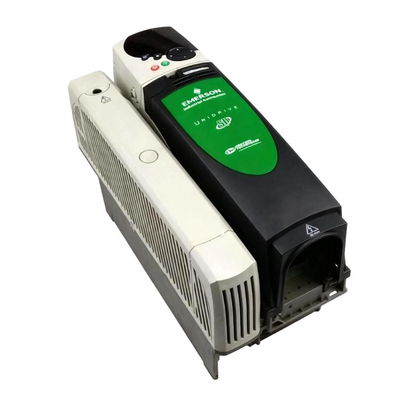
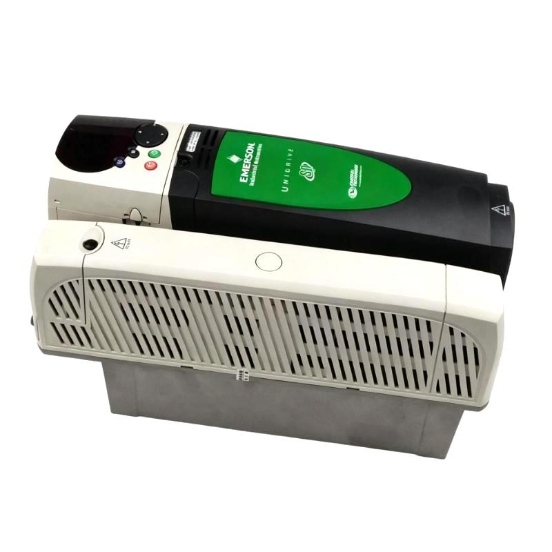
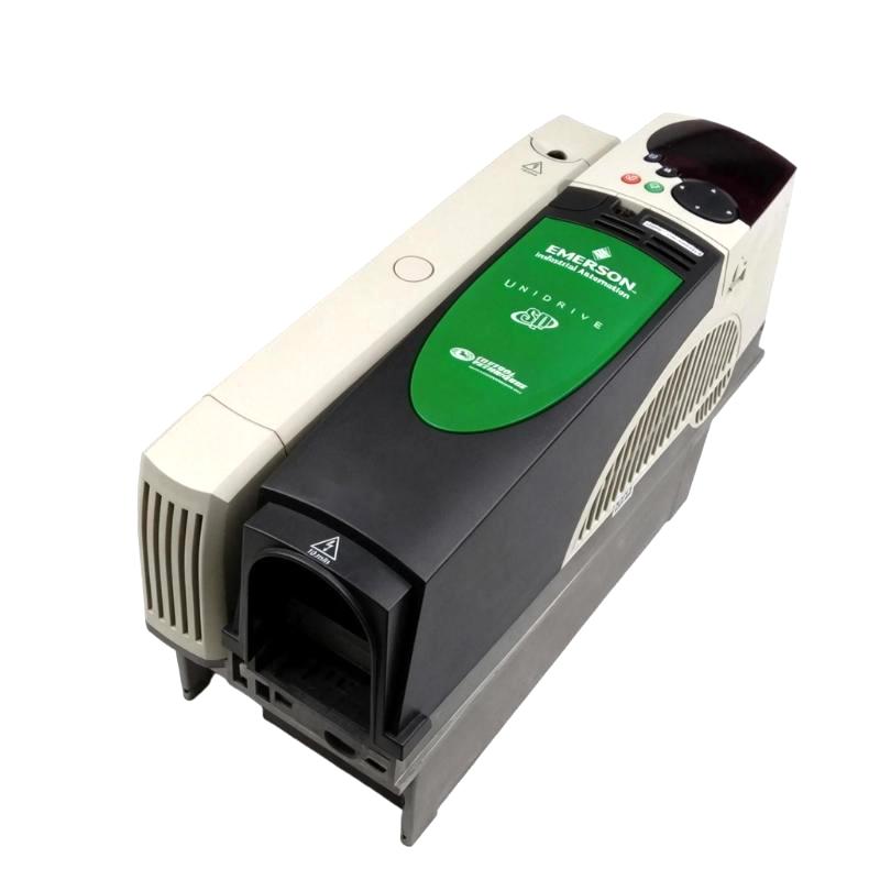
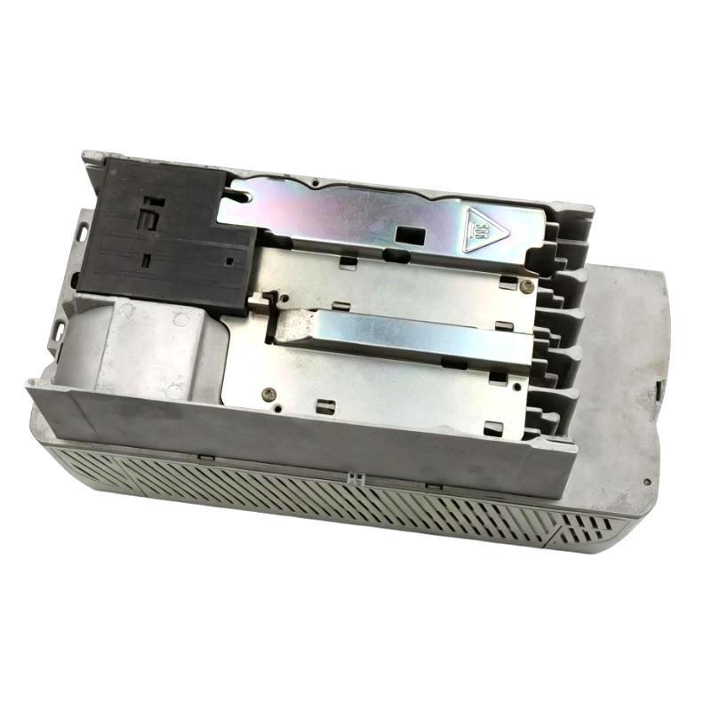
- Emerson
- SP2403
- AC Drive
- USA
- 368 × 155 × 219 mm
- 2 kg
- Xiamen, China
- New & In Stock
- T/T, PayPal, Western Union
- 1 Year
- 1-3 Working Days
- DHL, UPS, TNT, FedEx and EMS.
- 24-Hour Service
- COO
- 6
Our advantage

Global Logistics
We have a 10-year logistics and express cooperation agreement, so our products can be shipped to any place in the world.

Brand new and original
Our products are imported in bulk from the place of origin. Because of the cooperative relationship, our products are all original and 100% new.

24-hour service
We provide 7*24 hours service to our customers. We will be there whenever you need us.

Price advantage
All our products are priced very favorably because we have our own warehouse and supply.
| Company Information | |||
| [email protected] | |||
| Mobile | +8615980777398 | ||
| +8615980777398 | |||
| 15980777398 |
Product Overview
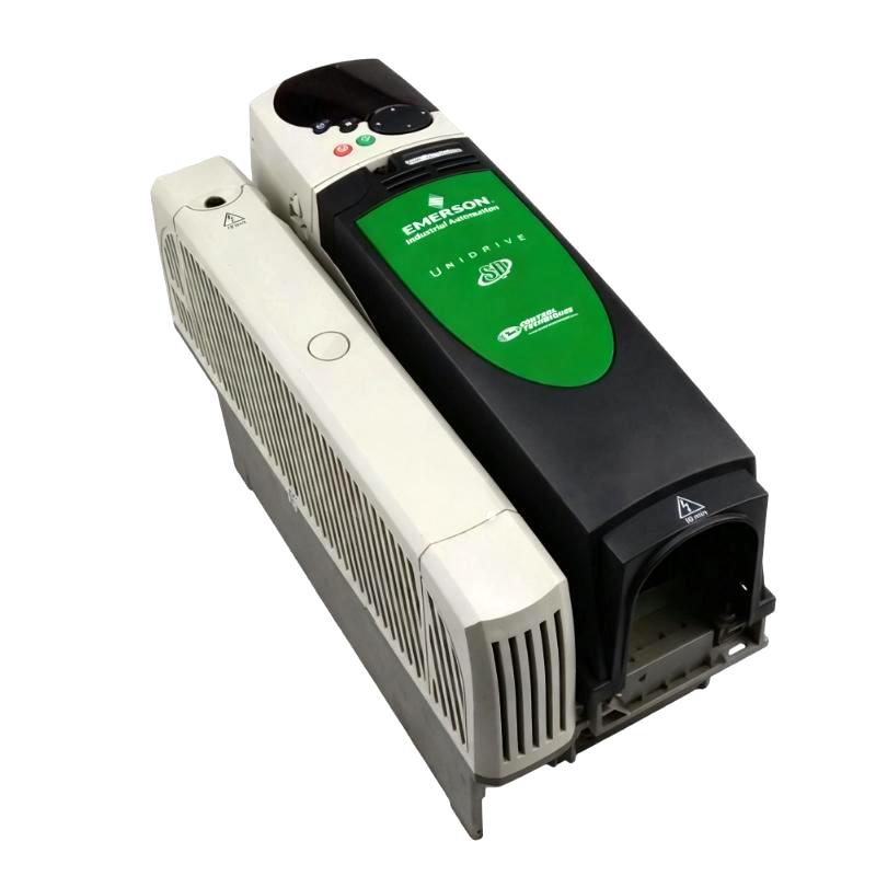
The Emerson SP2403 Unidrive SP Series AC Drive is a universal AC and servo drive for industrial machinery requiring variable-speed operation, configurable torque response and integration with automated control systems. Its Size 2 platform supports applications with higher motor-current requirements than the SP1400 models, including production equipment that must maintain controlled motor behavior as process loads change.
For the 380–480 V three-phase model, the SP2403 is rated at 25 A Heavy Duty output current and 29 A Normal Duty output current under the applicable rating conditions. It supports several motor-control approaches, including open-loop vector control, V/Hz control, rotor flux control, closed-loop induction motor control and compatible servo operation. The appropriate configuration depends on the motor, required control performance and application.
In a machine-control system, the SP2403 receives operating commands and speed or torque references, then regulates motor output according to its configured parameters. Its onboard Modbus RTU interface supports communication with compatible automation equipment, while optional modules can add network, feedback or application-specific functions. These capabilities make commissioning settings, process coordination and fault diagnosis important parts of configuring the drive for a specific machine.
Technical Specifications
| Parameter | Specification |
|---|---|
| Manufacturer | Emerson / Control Techniques |
| Model | SP2403 |
| Product Series | Unidrive SP |
| Product Type | Universal AC and Servo Drive |
| Frame Size | Size 2 |
| Input Supply | Three-phase AC |
| Input Voltage | 380–480 V AC |
| Input Frequency | 48–65 Hz |
| Heavy Duty Continuous Output Current | 25 A |
| Normal Duty Continuous Output Current | 29 A |
| Typical Motor Power at 400 V, Heavy Duty | 11 kW |
| Typical Motor Power at 400 V, Normal Duty | 15 kW |
| Motor Control Modes | Open-loop V/Hz, open-loop vector, rotor flux control, closed-loop induction motor control and compatible servo control |
| Analog Inputs | 3 |
| Analog Outputs | 2 |
| Digital Inputs | 7 |
| Digital Outputs | 3 |
| Relay Outputs | 1 |
| Onboard Communication | Modbus RTU |
| Option Slots | 3 |
| Feedback Expansion | Compatible feedback option modules |
| Enclosure Protection | IP20 for the panel-mount version |
| Dimensions | 368 × 155 × 219 mm |
| Weight | 2 kg |
Product Features
- High output-current capacity: Supports 25 A Heavy Duty and 29 A Normal Duty continuous output-current ratings for appropriately matched motor applications.
- Multiple motor-control modes: Supports different control strategies for compatible induction motors and servo applications.
- Adjustable speed and torque response: Allows control behavior to be configured according to the driven machine and process.
- Integrated analog and digital I/O: Supports external references, operating commands and configured status signals.
- Onboard Modbus RTU: Enables supported drive data exchange with compatible controllers and monitoring equipment.
- Three option slots: Accommodates compatible expansion modules for communication, feedback and additional functions.
- Programmable acceleration and deceleration: Helps match motor response to load inertia and process timing.
- Feedback-based control capability: Supports compatible feedback options for applications requiring closed-loop operation.
- Diagnostic functions: Provides fault and operating-state information for commissioning and troubleshooting.
- Application-specific configuration: Allows motor parameters, control modes and operating limits to be tailored to the intended application.
Working Principle
The SP2403 converts three-phase AC input power into a controlled electrical output for the connected motor. Its power electronics regulate the output according to the selected control mode, programmed motor data and active reference commands. Depending on the application, the drive can operate with open-loop control or use a compatible feedback arrangement for closed-loop operation.
The model’s output-current rating is 25 A in Heavy Duty operation and 29 A in Normal Duty operation. These ratings apply under their respective operating conditions, and the appropriate duty must be selected according to motor current, overload requirements and load behavior. The actual operating environment and switching-frequency configuration can also affect the permissible continuous current.
Control references and programmed ramp settings determine how the motor responds to changes in demand. On equipment with high inertia, frequent stopping or rapid speed changes, the deceleration strategy and braking arrangement need to be assessed together. In feedback-based applications, the feedback device and its configuration must also match the selected control mode.
When the drive trips, the recorded fault and operating conditions provide the starting point for diagnosis. Checking supply stability, motor connections, control references, feedback signals and load conditions can help isolate the cause before any parameter changes are made.
Role in an Industrial Motor Control Architecture
The SP2403 functions as the motor-control layer between the electrical supply, machine controller and driven equipment. It executes the configured control strategy, regulates motor output and returns supported operating information for supervision and fault handling.
| System Component | Function | Relationship to the Drive |
|---|---|---|
| Three-Phase AC Supply | Supplies electrical input power | Feeds the drive through appropriately rated isolation and protective devices |
| AC Induction Motor | Converts electrical power into mechanical motion | Receives the drive’s controlled output |
| Compatible Servo Motor | Provides controlled motion in supported applications | Requires a suitable control mode and compatible configuration |
| PLC or Machine Controller | Coordinates machine sequencing | Sends compatible run commands, references and enable signals |
| Analog Reference Source | Supplies a variable speed or process reference | Connects to a configured compatible analog input |
| Digital Control Circuit | Carries run, stop and interlock signals | Uses the drive’s supported digital I/O |
| Modbus RTU Master | Exchanges supported drive data | Communicates through the onboard serial interface |
| Encoder or Feedback Device | Supplies speed or position information where required | Requires a compatible feedback interface and supported control mode |
| Braking Arrangement | Manages regenerated energy during applicable stopping cycles | Must be selected according to the load and drive configuration |
| Supervisory System | Displays operating status and diagnostic information | Uses supported communication or controller-mapped signals |
Industrial Applications
| Application | Operating Requirement | Role of the SP2403 |
|---|---|---|
| Industrial Conveyor Lines | Coordinate speed with material flow and production timing | Regulates motor speed through configured references and operating limits |
| Extrusion and Material Processing | Maintain motor response as process loads change | Applies configured control parameters and current limits |
| Pumps and Fluid Handling Systems | Adjust motor operation to changing process demand | Supports variable-speed control when the motor and pump are appropriately matched |
| Fans and Blowers | Adjust airflow through motor-speed control | Changes motor speed in response to the required reference |
| Winding and Unwinding Equipment | Coordinate motor speed or torque with line conditions | Supports suitable configured speed or torque-control strategies |
| Packaging Machinery | Match motor response to machine-cycle timing | Executes programmed speed and ramp settings |
| Cutting and Processing Machines | Coordinate motor operation with production commands | Provides configurable motor control within the drive’s ratings |
| General Industrial Machinery | Integrate motor operation with automation logic | Processes compatible commands and supplies status and fault information |
Installation and Maintenance
- Verify the model designation: Confirm that the installed drive is an SP2403 and that its electrical ratings match the intended motor and application.
- Check the incoming supply: Verify the three-phase supply voltage and frequency against the drive’s rating information before connecting power.
- Inspect the drive assembly: Check accessible terminals, connectors and the enclosure for damage, contamination or signs of overheating.
- Provide adequate ventilation: Follow the applicable mounting clearances and cooling requirements to manage heat inside the control panel.
- Verify protective grounding: Ensure that protective-earth connections comply with the electrical design and applicable installation requirements.
- Select the appropriate duty rating: Compare the motor’s rated current and overload requirements with the 25 A Heavy Duty and 29 A Normal Duty ratings.
- Inspect motor wiring: Verify conductor sizing, terminal tightness, insulation and cable routing before energizing the drive.
- Check feedback connections: For closed-loop applications, verify the feedback device, interface compatibility, wiring and signal integrity.
- Configure motor parameters: Enter the required motor data and confirm that the selected control mode suits the motor and load.
- Review stopping behavior: Set acceleration and deceleration parameters according to the mechanical load, cycle time and braking requirements.
- Test I/O and communication: Verify command response, reference scaling, Modbus RTU settings and installed option modules before production use.
- Record commissioning results: Document motor data, duty selection, control parameters, installed options, fault history and functional test results.
Compatible System Components
| Component | Function | Compatibility Consideration |
|---|---|---|
| Compatible AC Induction Motor | Produces mechanical output | Verify voltage, rated current and control requirements against the drive |
| Supported Servo Motor | Provides controlled motion in suitable applications | Confirm the required control mode and motor compatibility |
| PLC or Machine Controller | Coordinates machine logic | Confirm supported command signals and interface arrangements |
| Analog Reference Source | Supplies a speed or process reference | Match signal type and scaling to the configured input |
| Encoder or Feedback Device | Provides speed or position information | Requires a compatible feedback option and supported device |
| Modbus RTU Master | Exchanges supported drive information | Configure serial settings and supported data mapping |
| Communication Option Module | Adds a supported network interface | Verify the exact module and protocol compatibility |
| Braking Components | Support applicable deceleration requirements | Select according to the load and drive configuration |
| Upstream Protective Device | Protects the input supply circuit | Select according to the electrical installation design |
Recommended Related Models
| Model | Product Type | Relationship | Selection Consideration |
|---|---|---|---|
| Emerson SP1406 | Unidrive SP AC Drive | Smaller-frame model with lower current capacity | Compare its output-current ratings with the motor’s requirements |
| Emerson SP2401 | Unidrive SP AC Drive | Lower-current model in the same frame group | Check whether its 13 A Heavy Duty and 15.3 A Normal Duty ratings are sufficient |
| Emerson SP2402 | Unidrive SP AC Drive | Lower-current model in the same frame group | Compare its 16.5 A Heavy Duty and 21 A Normal Duty ratings with the load |
| Emerson SP3401 | Unidrive SP AC Drive | Related model from a larger frame group | Evaluate the required current capacity, mounting arrangement and installation conditions |
Key Advantages
- Provides 25 A Heavy Duty and 29 A Normal Duty continuous output-current ratings.
- Supports multiple control modes for compatible induction motor and servo applications.
- Offers configurable speed and torque response for industrial machinery.
- Includes integrated analog and digital I/O and onboard Modbus RTU.
- Supports compatible feedback and communication expansion modules.
- Supplies diagnostic information to assist commissioning and fault investigation.
Technical FAQs
How can the SP2403 be configured for a motor that must maintain torque as speed decreases?
Choose a control mode suited to the motor and torque requirement, then verify motor data and operating limits. If the application requires closed-loop performance, confirm that the feedback device and interface are compatible and correctly configured before tuning the control response.
What should be checked if the SP2403 develops excess heat during continuous operation?
Review the actual output current, selected duty rating, ambient temperature, switching-frequency configuration and panel ventilation. Also check for sustained overload or an unsuitable motor application before changing operating parameters.
How can the SP2403’s built-in PLC functions be used in a machine sequence?
Where the required functionality is supported by the installed configuration, drive-resident logic can handle selected control tasks locally. Confirm the available programming functions, I/O assignments and interaction with the main PLC, then test interlocks and fault behavior before commissioning.
What should be investigated when a feedback-controlled SP2403 reports inconsistent motor speed?
Check feedback wiring, signal quality, encoder configuration, the selected feedback interface and the programmed motor data. Also inspect the mechanical coupling and verify that the feedback device is appropriate for the speed range and operating conditions.