

ProductPRODUCT
Featured products
Contact Us
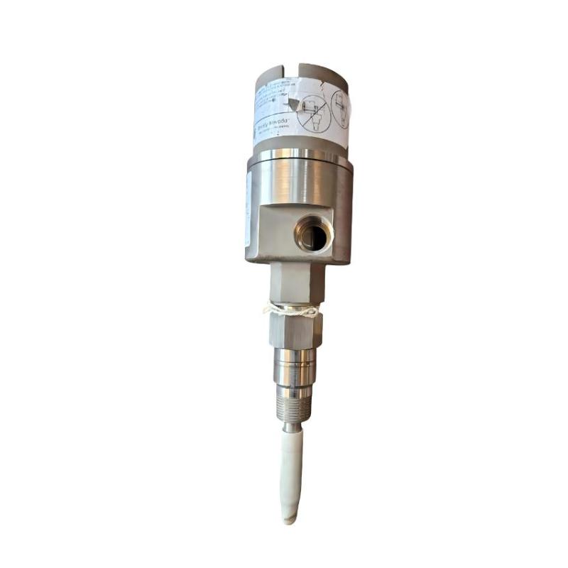
- Bently Nevada
- CA24701-28-10-35-027-03-02
- Explosion-Proof Housing Assembly
- USA
- 1 meter
- 1.8 kg
- Xiamen, China
- New & In Stock
- T/T, PayPal, Western Union
- 1 Year
- 1-3 Working Days
- DHL, UPS, TNT, FedEx and EMS.
- 24-Hour Service
- COO
- 6
Our advantage

Global Logistics
We have a 10-year logistics and express cooperation agreement, so our products can be shipped to any place in the world.

Brand new and original
Our products are imported in bulk from the place of origin. Because of the cooperative relationship, our products are all original and 100% new.

24-hour service
We provide 7*24 hours service to our customers. We will be there whenever you need us.

Price advantage
All our products are priced very favorably because we have our own warehouse and supply.
| Company Information | |||
| [email protected] | |||
| Mobile | +8615980777398 | ||
| +8615980777398 | |||
| 15980777398 |
Product Overview
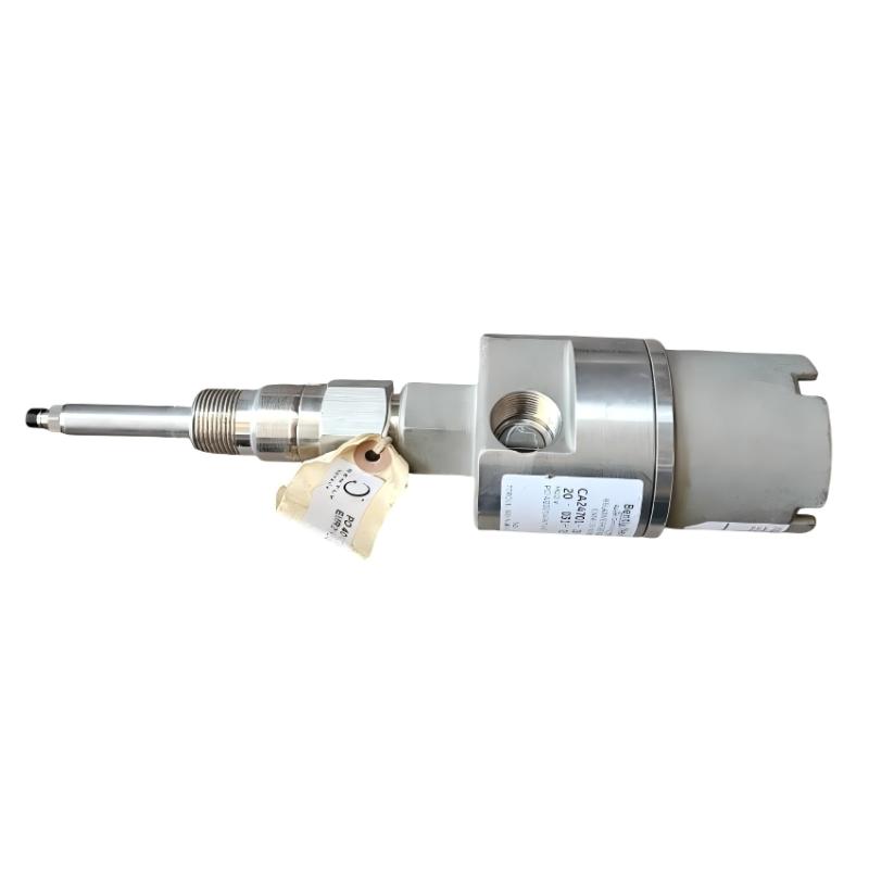
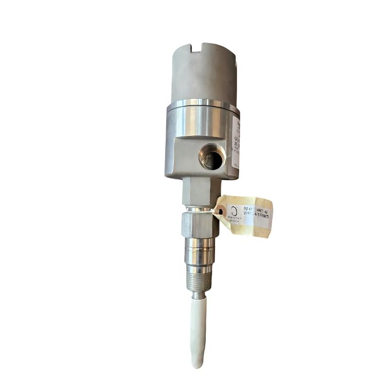
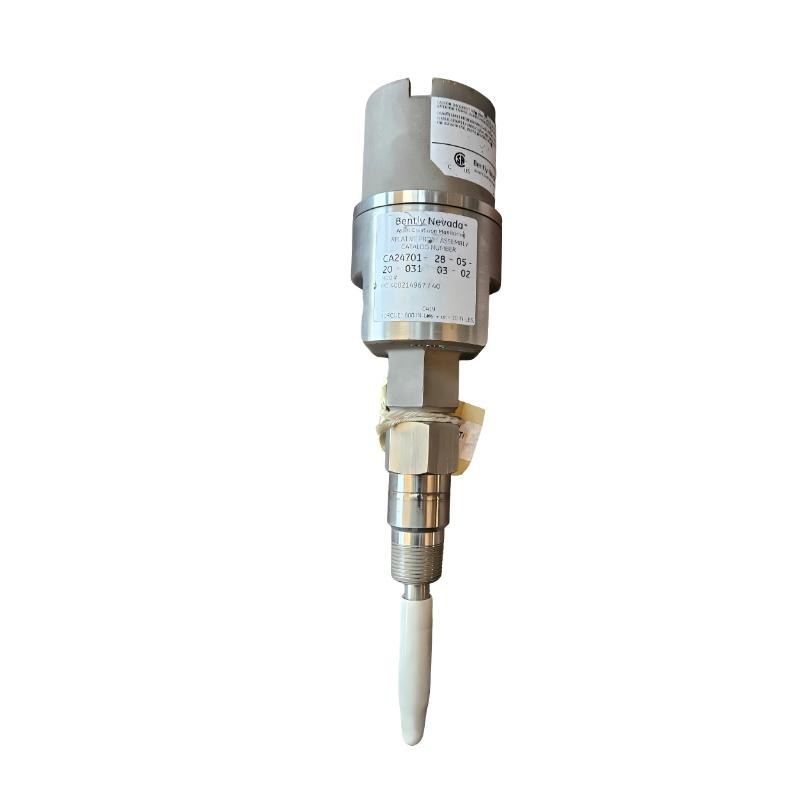
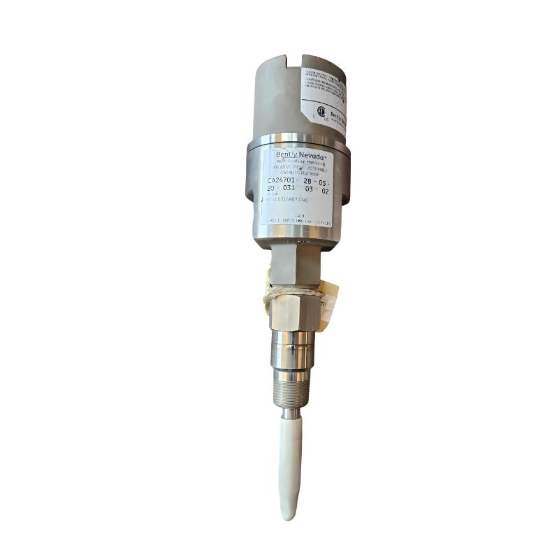
The Bently Nevada CA24701-28-10-35-027-03-02 Explosion-Proof Housing Assembly is a stainless-steel proximity probe housing configuration for machinery condition monitoring in hazardous industrial environments. It belongs to the 24701 housing family and combines a 3300 XL 8 mm proximity probe configuration with a 1-meter probe cable, a standoff adapter, a defined probe penetration length and cable-entry fittings.
The housing allows a proximity probe to be installed externally while maintaining a protected arrangement around the probe and its cable connection. In rotating machinery monitoring, the probe measures the position of a conductive target, such as a shaft surface, without direct mechanical contact. The resulting displacement signal can be used by a compatible proximity transducer system to monitor shaft vibration and relative shaft position.
The selected configuration includes a 3.5-inch standoff adapter, a 2.7-inch probe penetration option, cable seal-grip fittings and a 3/4-14 NPT mounting thread. These options determine how the probe is positioned relative to the machine, how the cable enters the housing and how the assembly interfaces with the installation. Correct configuration matching is important when replacing an existing housing assembly or integrating it into an established monitoring system.
Technical Specifications
| Parameter | Specification |
|---|---|
| Manufacturer | Bently Nevada |
| Model | CA24701-28-10-35-027-03-02 |
| Product Family | 24701 Proximity Probe Housing Assemblies |
| Product Type | Explosion-Proof Housing Assembly |
| Housing Material | 303 stainless steel body with 304 stainless steel sleeve |
| Probe Configuration | 3300 XL 8 mm proximity probe, multiple approvals |
| Probe Cable Length | 1 meter |
| Standoff Adapter Length | 3.5 inches (approximately 89 mm) |
| Probe Penetration Length | 2.7 inches (approximately 69 mm) |
| Cable Entry Fittings | Cable seal grip with grommets |
| Mounting Thread | 3/4-14 NPT |
| Probe System Type | Eddy-current proximity measurement |
| Intended Monitoring Application | Non-contact shaft displacement and vibration monitoring with a compatible transducer system |
| Housing Protection | Explosion-proof configuration, subject to applicable approvals and installation requirements |
| Weight | 1.8 kg |
Product Features
- Stainless-steel housing construction: Uses a 303 stainless-steel body and a 304 stainless-steel probe sleeve for industrial installation.
- 3300 XL 8 mm probe configuration: Accommodates the specified proximity probe family for non-contact machinery monitoring.
- 1-meter probe cable: Matches the cable-length option specified in the model configuration.
- Defined standoff adapter: The 3.5-inch adapter option establishes the selected probe mounting arrangement.
- Specified probe penetration: The 2.7-inch penetration option determines how far the probe extends into the machine mounting arrangement.
- Cable seal-grip fittings: Provides cable-entry sealing components for the supported cable sizes.
- NPT mounting connection: Uses a 3/4-14 NPT mounting-thread option.
- Hazardous-area configuration: The CA housing designation relates to the applicable explosion-proof housing configuration; actual approval depends on the selected options and installation conditions.
- External probe protection: Encloses the probe mounting arrangement and helps protect the installed assembly from its surrounding environment.
- Condition-monitoring integration: Supports installation of a compatible proximity probe as part of a machinery monitoring system.
Working Principle
The housing provides the mechanical mounting and protection arrangement for the proximity probe. Once installed and correctly positioned, the probe operates as part of an eddy-current measurement system. Its sensing tip faces a conductive machine target, typically a rotating shaft, and generates a signal that varies with the distance between the probe tip and the target.
A compatible proximity transducer converts the probe’s electrical response into a signal suitable for machinery monitoring. Depending on the monitoring configuration, the resulting measurement can be used to evaluate shaft vibration, relative shaft displacement or changes in shaft position. The housing itself does not calculate vibration or generate the complete monitoring output; these functions depend on the probe, extension cable and compatible transducer electronics.
The selected standoff adapter and probe penetration options establish the mechanical geometry between the housing and the target. Incorrect positioning can affect the available adjustment range, probe clearance and measurement setup. During installation, the probe gap must be set according to the applicable probe-system instructions and the machine’s measurement requirements.
The cable seal grip and threaded connections form part of the installation’s cable-entry and mounting arrangement. In hazardous locations, all housing fittings, electrical connections and associated monitoring equipment must be suitable for the area classification. The completed assembly must follow the applicable approval conditions rather than relying on the housing model number alone.
Role in a Bently Nevada Machinery Condition Monitoring Architecture
The CA24701-28-10-35-027-03-02 serves as the mechanical housing and probe-mounting assembly within a proximity-based machinery monitoring installation. The probe senses shaft movement, compatible transducer electronics process the probe signal, and the monitoring system uses the resulting data to assess machinery condition.
| System Component | Function | Relationship to the CA24701 Housing Assembly |
|---|---|---|
| 3300 XL 8 mm Proximity Probe | Senses the distance to a conductive target | Installed in the housing’s specified probe configuration |
| Probe Extension Cable | Carries the probe signal to compatible electronics where required by the system arrangement | Must match the probe and transducer system |
| Proximity Transducer | Converts the probe response into a usable monitoring signal | Processes the signal generated by the installed probe |
| Machinery Monitoring Module | Acquires and evaluates measurement signals | Uses the transducer output for vibration or displacement monitoring |
| Shaft or Conductive Target | Provides the surface measured by the probe | Must be positioned within the probe’s intended measurement range |
| Standoff Adapter | Establishes the selected mounting geometry | Uses the specified 3.5-inch option |
| Cable Seal Grip | Supports cable entry into the housing | Must match the installed cable diameter and fitting arrangement |
| NPT Mounting Connection | Provides the specified threaded installation interface | Uses the selected 3/4-14 NPT option |
| Monitoring Software | Displays trends, alarms and measurement values | Interprets the acquired monitoring data |
| Hazardous-Area Installation | Provides the site-specific protection and installation framework | Must satisfy the applicable approval and wiring requirements |
Industrial Applications
| Application | Monitoring Requirement | Role of the CA24701 Assembly |
|---|---|---|
| Steam Turbines | Monitor relative shaft vibration and position | Provides the mounting arrangement for a compatible proximity probe |
| Industrial Gas Turbines | Acquire shaft displacement measurements | Supports probe installation within a suitable machinery monitoring system |
| Centrifugal Compressors | Monitor shaft movement and vibration trends | Houses the probe used to measure the conductive shaft target |
| Large Industrial Pumps | Track shaft behavior during operation | Provides a protected mounting arrangement for proximity sensing |
| Power Generation Equipment | Supply shaft measurement signals to condition-monitoring systems | Integrates the probe into the machine’s measurement setup |
| Refinery Rotating Machinery | Monitor machinery in classified industrial areas | Supports installation where the selected housing and complete system meet applicable hazardous-area requirements |
| Petrochemical Process Equipment | Measure shaft movement for machinery diagnostics | Provides the mechanical interface for a compatible probe system |
| Continuous-Process Machinery | Maintain consistent probe positioning for long-term monitoring | Uses the specified adapter and penetration options to establish mounting geometry |
Installation and Maintenance
- Verify the complete part number: Confirm that the housing assembly is CA24701-28-10-35-027-03-02 and that all option codes match the required installation.
- Confirm hazardous-area suitability: Check the applicable area classification, certification requirements and permitted fitting configuration before installation.
- Inspect the housing body: Check the stainless-steel body, cover, sleeve and sealing surfaces for damage, corrosion or contamination.
- Verify the probe configuration: Confirm that the installed probe matches the specified 3300 XL 8 mm configuration and its required approval options.
- Check the cable length: Ensure the 1-meter cable arrangement is suitable for the installation and does not become trapped or excessively coiled inside the housing.
- Confirm the adapter geometry: Verify the selected 3.5-inch standoff adapter and its compatibility with the machine mounting arrangement.
- Check probe penetration: Confirm that the 2.7-inch penetration option provides the required installation geometry and adjustment range.
- Inspect threaded connections: Verify the 3/4-14 NPT mounting interface and use compatible fittings and sealing practices for the installation.
- Verify cable seal-grip sizing: Match the supplied grommets to the cable diameter and confirm that the cable-entry arrangement is assembled correctly.
- Set the probe gap: Establish the required probe-to-target gap according to the applicable probe-system instructions and measurement setup.
- Test the monitoring signal: Confirm that the probe and compatible transducer produce an appropriate signal before returning the monitored machine to service.
- Record maintenance findings: Document the installed option codes, probe position, cable routing, fitting condition and monitoring-system test results.
Compatible System Components
| Component | Function | Compatibility Consideration |
|---|---|---|
| Bently Nevada 3300 XL 8 mm Proximity Probe | Measures the distance to a conductive target | Match the probe configuration and hazardous-area approval requirements |
| Compatible 3300 XL Extension Cable | Carries the probe signal in supported system arrangements | Verify cable type, length and compatibility with the probe and transducer |
| Compatible Proximity Transducer | Converts the probe response into a monitoring signal | Confirm the complete probe-extension cable-transducer combination |
| 3300 Series Machinery Monitoring System | Acquires and processes machinery measurements | Verify channel type and monitoring-system compatibility |
| 3/4-14 NPT Fittings | Provide threaded mounting or conduit interfaces | Match thread type, enclosure arrangement and hazardous-area requirements |
| Cable Seal-Grip Grommets | Seal and support the cable entry | Select the correct grommet size for the cable diameter |
| Conductive Shaft Target | Provides the surface measured by the probe | Confirm target material, geometry and measurement clearance |
| Hazardous-Area Cable System | Routes electrical connections in classified locations | Use components suitable for the site classification and approval conditions |
Recommended Related Models
| Model | Product Type | Relationship | Selection Consideration |
|---|---|---|---|
| Bently Nevada CA24701-28-10-35-027-03-02 | Explosion-Proof Housing Assembly | Exact configuration for replacement | Match all option codes, including probe, cable, adapter, penetration and fittings |
| Bently Nevada 24701 Proximity Probe Housing Assembly | Stainless-Steel Proximity Probe Housing Assembly | Related housing family | Confirm whether the non-CA configuration meets the installation requirements |
| Bently Nevada CA21000 Proximity Probe Housing Assembly | Explosion-Proof Proximity Probe Housing Assembly | Related housing family with a different body material | Check material requirements, mounting geometry and probe configuration |
| Bently Nevada 3300 XL 8 mm Proximity Probe | Proximity Probe | Sensing component associated with the specified configuration | Match probe length, connector, cable and approval options |
| Bently Nevada 3300 XL Proximity Transducer System | Proximity Measurement System | Associated measurement technology | Verify compatibility among probe, extension cable and transducer |
Key Advantages
- Provides a stainless-steel housing configuration for proximity probe installation.
- Matches a defined 3300 XL 8 mm probe and 1-meter cable arrangement.
- Specifies the standoff adapter and probe penetration options for installation planning.
- Includes cable seal-grip fittings and a 3/4-14 NPT mounting-thread option.
- Supports integration into compatible shaft vibration and displacement monitoring systems.
- Offers a CA housing configuration for applications where the relevant hazardous-area approvals are satisfied.
Technical FAQs
What does the “28” option specify in this CA24701 model number?
The “28” option identifies a 3300 XL series 8 mm proximity probe configuration with multiple approvals. The complete probe and monitoring-system configuration must still match the installation’s electrical and hazardous-area requirements.
How do the 3.5-inch adapter and 2.7-inch penetration options affect installation?
The adapter option establishes the standoff between the mounting interface and the probe arrangement, while the penetration option defines the selected probe extension into the machine installation. Together, they determine the mechanical geometry and available adjustment. Verify the actual mounting dimensions and probe clearance before installation.
Does the CA24701 designation alone guarantee explosion-proof approval for every installation?
No. The applicable approval depends on the housing version, selected fitting options, associated probe configuration and installation conditions. The complete assembly must meet the requirements for the site’s hazardous-area classification.
What should be checked if the probe is installed but the monitoring system shows an unstable signal?
Check the probe gap, cable and connector condition, grounding and shielding arrangements, transducer compatibility, and the condition of the target surface. Also confirm that the probe, extension cable and transducer form a compatible system and that the housing is securely mounted.