

ProductPRODUCT
Featured products
Contact Us
- ABB
- AF460-30-11-71 1SFL597001R7111
- DC Contactor
- Sweden (SE)
- 278 × 186 × 216 mm
- 10.6 kg
- Xiamen, China
- New & In Stock
- T/T, PayPal, Western Union
- 1 Year
- 1-3 Working Days
- DHL, UPS, TNT, FedEx and EMS.
- 24-Hour Service
- COO
- 6
Our advantage

Global Logistics
We have a 10-year logistics and express cooperation agreement, so our products can be shipped to any place in the world.

Brand new and original
Our products are imported in bulk from the place of origin. Because of the cooperative relationship, our products are all original and 100% new.

24-hour service
We provide 7*24 hours service to our customers. We will be there whenever you need us.

Price advantage
All our products are priced very favorably because we have our own warehouse and supply.
| Company Information | |||
| [email protected] | |||
| Mobile | +8615980777398 | ||
| +8615980777398 | |||
| 15980777398 |
Product Overview
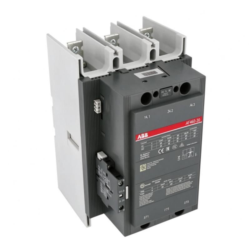
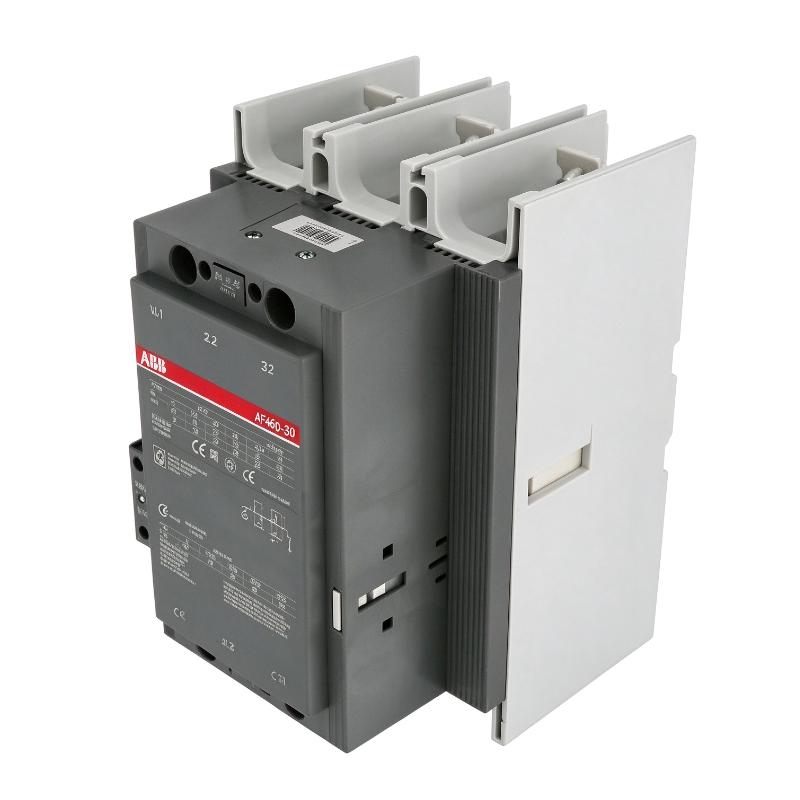
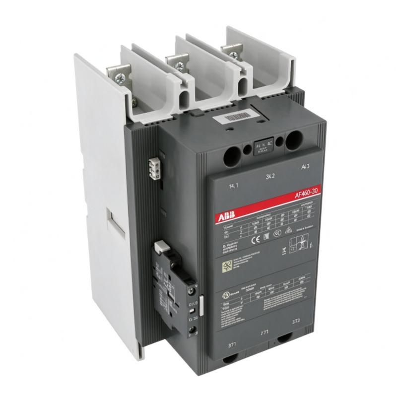
The ABB AF460-30-11-71 1SFL597001R7111 Contactor is a heavy-duty three-pole contactor designed for industrial power switching and motor-control applications. It belongs to ABB’s AF contactor family and is intended for installations that require reliable switching of high-current electrical circuits, including motor starting, isolation, bypass operation, and power distribution.
A contactor is an electrically controlled switching device that allows a control circuit to operate a separate power circuit. When its coil is energized, the contactor’s main contacts close to establish the electrical connection. When the coil is de-energized, the contacts return to their normal state, interrupting the controlled circuit. This arrangement allows control systems to manage substantial electrical loads without requiring operators or low-voltage control equipment to switch the main power circuit directly.
The AF460-30-11-71 uses ABB’s AF electronic coil technology. Its wide control voltage range supports operation with either 250–500 V AC at 50/60 Hz or 250–500 V DC. This helps accommodate control supplies that may experience voltage variations within the specified operating limits.
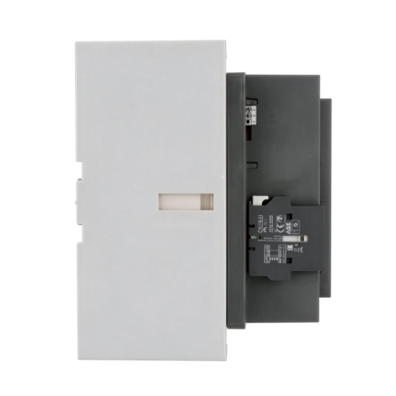
The contactor has three normally open main contacts and pre-mounted auxiliary contacts, including one normally open and one normally closed auxiliary contact. These auxiliary contacts can support status feedback, electrical interlocking, and control-sequence logic when correctly integrated into the application.
The model is designed for demanding industrial power circuits. Its published ratings include a maximum rated operational voltage of 1000 V under IEC specifications, an AC-3 operational current of 460 A at 380–440 V, and an AC-1 operational current of up to 700 A at specified ambient conditions. These ratings apply to different utilization categories and must not be treated as interchangeable.
For replacement and procurement purposes, the complete catalog number, coil voltage, contact arrangement, terminal configuration, and application duty should be checked before ordering. A contactor with a similar current rating may not provide the same coil-control characteristics or switching performance.
Technical Specifications
| Parameter | Specification |
|---|---|
| Brand | ABB |
| Product Series | AF Contactors |
| Model | AF460-30-11-71 |
| Product ID | 1SFL597001R7111 |
| Product Type | Three-Pole Power Contactor |
| Main Contact Configuration | 3 normally open contacts |
| Auxiliary Contacts | 1 normally open + 1 normally closed |
| Coil Operating Voltage | 250–500 V AC, 50/60 Hz; 250–500 V DC |
| Main Circuit Rated Operational Voltage | Up to 1000 V IEC |
| Maximum Main Circuit Voltage, UL | 600 V AC |
| Rated Operational Current, AC-3 | 460 A at 380–440 V, 55°C reference condition |
| Rated Operational Current, AC-1 | Up to 700 A at specified conditions |
| Rated Operational Power, AC-3 | 250 kW at 380–440 V |
| UL Horsepower Rating | Up to 400 hp at 440–480 V, three-phase |
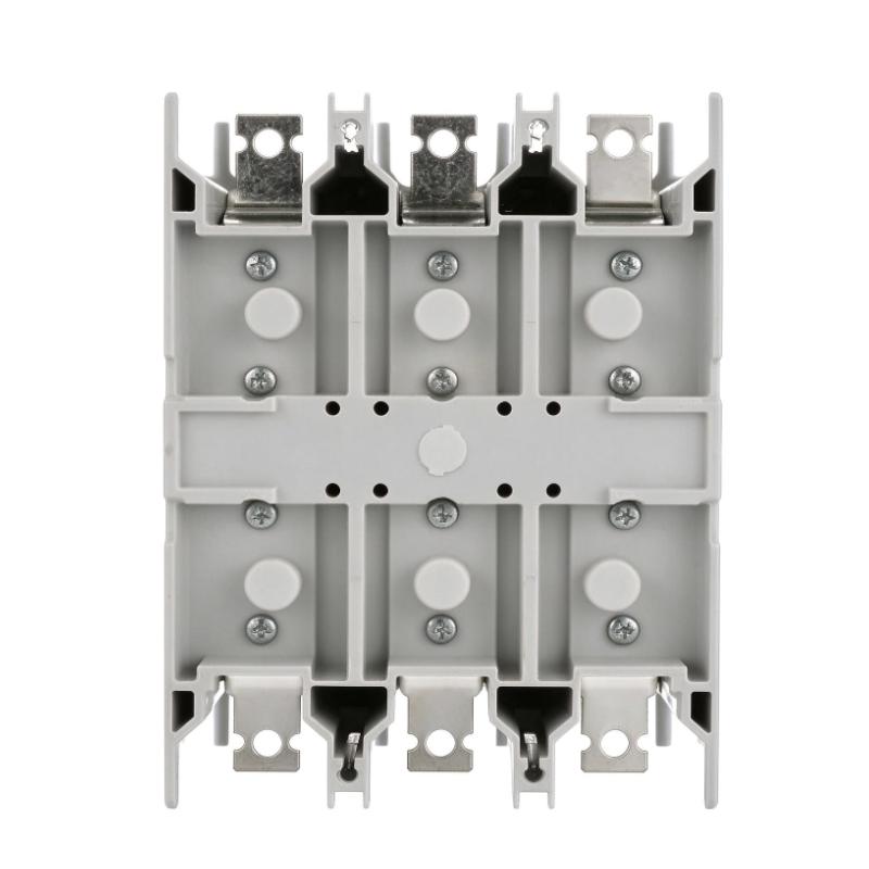
| Main Circuit Connection | Bus bars |
| Surge Protection | Built-in |
| Mechanical Durability | Approximately 5 million operating cycles |
| Main Terminal Protection | IP00 |
| Coil Terminal Protection | IP20 |
| Dimensions Provided | 278 × 186 × 216 mm |
| Weight Provided | 10.6 kg |
| Typical Applications | Motor starting, isolation, bypass, power distribution |
Important: AC-1, AC-3, and UL ratings represent different operating conditions and standards. Always select the contactor according to the applicable motor, load, voltage, switching frequency, and protection requirements. The dimensions and weight above are the supplied listing values.
Function and Working Principle
The ABB AF460-30-11-71 controls the connection and disconnection of an industrial electrical load through an electromagnetic switching mechanism. Its main contacts carry the power current, while the control coil determines when the contacts change state.
1. Electromagnetic Switching
When the control voltage is applied to the coil, the contactor’s operating mechanism moves the main contacts into the closed position. This allows current to flow through the connected power circuit.
When the coil is de-energized, the mechanism returns to its normal position and opens the main contacts. The connected load is then disconnected, subject to the circuit design and the switching device’s rated capabilities.
This principle allows a PLC, relay logic circuit, or other suitable control device to manage a high-current load through an appropriate control interface.
2. Three-Pole Main Circuit
The AF460-30-11-71 has three normally open main contacts, making it suitable for switching three-phase power circuits.
In a typical motor-control installation, the three main poles switch the three phase conductors supplying a motor. The contactor is often used with upstream short-circuit protection and a suitable motor overload protection device.
The contactor itself should not be treated as a substitute for a circuit breaker, fuse, or motor overload relay.
3. Wide-Range Electronic Coil
The AF contactor’s electronic coil technology supports a wide control voltage range of 250–500 V AC at 50/60 Hz or 250–500 V DC for this particular model.
This broad range can simplify control-system design where the available control supply varies within the permitted limits. It also helps the contactor operate reliably under specified control-voltage variations.
The coil supply must remain within the manufacturer’s operating limits. The 250–500 V coil rating is separate from the voltage rating of the main power circuit.
4. Auxiliary Contact Feedback
The contactor includes one normally open and one normally closed auxiliary contact. These contacts can be used in control logic to indicate contactor state, establish interlocks, or permit subsequent operations only after the appropriate switching condition is reached.
For example, an auxiliary contact may be connected to a PLC input to provide feedback about the commanded contactor state. The feedback circuit must be designed according to the auxiliary contact ratings and the required control-system architecture.
5. Power Circuit Switching
The contactor is designed for industrial switching applications involving motor loads and power distribution circuits. Its suitability depends on the load type and the applicable utilization category.
AC-1 is generally associated with non-inductive or slightly inductive loads, while AC-3 covers typical squirrel-cage motor starting and switching during normal running conditions. A contactor’s permitted current can differ significantly between these categories.
Correct application selection is therefore essential for electrical safety, contact life, and operational reliability.
Role in Industrial Control Systems
The AF460-30-11-71 can serve as a power-switching component in a wider industrial control system. It connects the power circuit to the load under commands from an electrical control circuit.
PLC-Based Motor Control
A programmable logic controller can determine when a motor should start or stop based on sensor inputs, production requirements, operating sequences, and safety interlocks.
The PLC typically operates the contactor coil through an appropriately rated control interface or intermediate relay. Auxiliary contacts can provide feedback to the control system where required.
Because this contactor’s coil requires a control voltage within the specified 250–500 V AC/DC range, the PLC output must not be connected directly unless the output device and interface are specifically rated for that voltage and load. In many systems, an intermediate switching device is required.
Motor Starter Assemblies
The contactor may be incorporated into a motor starter assembly together with suitable short-circuit protection and overload protection. This arrangement allows the control system to switch the motor while separate protective devices address fault currents and overload conditions.
For a motor installation, the engineer must select the contactor according to the motor’s rated current, starting characteristics, operating frequency, and required duty category.
Electrical Interlocking
Auxiliary contacts can support interlocking between contactors in forward/reverse motor circuits, bypass arrangements, and other switching sequences.
Interlocking helps prevent incompatible switching states from occurring at the same time. Where the application requires safety-related functions, dedicated safety architecture and appropriately rated components must be used rather than relying solely on standard auxiliary contacts.
Power Distribution and Bypass Systems
The AF460-30-11-71 can also be used in industrial distribution and bypass arrangements. The exact function depends on the circuit topology and the design of the wider electrical installation.
In bypass applications, the switching sequence must prevent unsafe or unintended parallel connections. Electrical and, where necessary, mechanical interlocking should be designed and validated for the specific system.
Industrial Applications
The ABB AF460-30-11-71 is intended for high-current industrial switching duties. Typical applications include the following.
1. Large Three-Phase Motor Starting
The contactor can be used to switch compatible three-phase motors in industrial plants. It may form part of a direct-on-line starter or another motor-control arrangement, provided the ratings and starting method are suitable.
The selection process should account for motor full-load current, starting current, operating frequency, and the applicable AC-3 rating.
2. Industrial Power Distribution
In distribution assemblies, the contactor can connect or disconnect a power circuit as part of an automated control sequence. Its rated voltage and current must match the actual switching duty.
Suitable upstream protective devices are essential, particularly where the prospective short-circuit current is high.
3. Bypass Circuits
Some industrial installations use bypass circuits to change the path through which power reaches a load. The AF460-30-11-71 may be considered for such arrangements when the switching sequence, contactor ratings, and interlocking design are appropriate.
The bypass design must account for the electrical characteristics of all connected equipment and must prevent unintended switching states.
4. Industrial Pumps and Fans
Large pumps and fans often require contactors as part of their motor starter and control systems. The contactor provides the switching function, while motor protection and control logic are handled by the corresponding devices.
For high-inertia or frequently switched loads, the selected contactor must be rated for the required utilization category and operating frequency.
5. Manufacturing and Process Plants
The contactor can be used in industrial production lines, utility systems, and process equipment where high-current switching is required.
Potential applications include central motor-control panels, auxiliary power circuits, and automated switching assemblies. Suitability depends on the actual circuit voltage, load current, duty cycle, and environmental conditions.
Installation and System Integration
Correct installation is necessary to maintain reliable switching performance and prevent overheating, insulation failure, or unintended operation.
1. Verify the Coil Control Voltage
Before installation, verify the available control supply and ensure it falls within the specified 250–500 V AC or 250–500 V DC range.
Do not confuse the coil operating voltage with the main circuit voltage. They serve different functions and must be verified separately.
2. Confirm Main Circuit Ratings
Check the main circuit voltage, load current, utilization category, and expected switching frequency. The contactor’s AC-1 and AC-3 ratings are not interchangeable.
For motor applications, use the applicable motor duty rating rather than selecting the contactor solely from its maximum thermal current.
3. Mounting and Panel Layout
The supplied dimensions are 278 × 186 × 216 mm. Confirm the manufacturer’s dimension drawing before fabricating the control panel or finalizing mounting clearances.
The contactor’s orientation, cable or bus-bar connections, ventilation, and service access should follow the installation instructions. High-current connections must be mechanically secure and suitable for the required conductor or bus-bar arrangement.
4. Main Circuit Wiring
The AF460-30-11-71 uses bus-bar connections for the main circuit. The conductors and bus bars must be selected for the rated current, installation temperature, and applicable electrical standards.
Ensure that the connections are tightened to the specified torque and that the assembly is protected against accidental contact. Main terminal protection is listed as IP00, so appropriate enclosure protection is essential.
5. Auxiliary and Control Wiring
Wire the normally open and normally closed auxiliary contacts according to the control schematic. Verify their ratings and confirm that the feedback logic matches the actual contactor arrangement.
Use a properly rated interface between low-voltage PLC outputs and the high-voltage contactor coil when required. Do not assume that a standard 24 V PLC output can directly operate this coil.
6. Short-Circuit and Overload Protection
The contactor should be coordinated with suitable upstream short-circuit protective devices. Motor applications also require appropriate overload protection unless the complete system design provides the required protection through another approved arrangement.
Protection selection must follow the manufacturer’s coordination tables and the applicable electrical codes.
7. Commissioning Checks
Before energizing the installation, inspect the wiring, terminal security, protective earth arrangements, control voltage, and interlocking circuits.
Test the contactor’s energization and release, auxiliary feedback, motor-starting sequence, and protective-device operation under controlled conditions. Record the final circuit configuration and maintenance information for future troubleshooting.
Compatible System Components
The AF460-30-11-71 is generally used as part of a complete electrical switching and motor-control assembly.
| Component | Function | Integration Considerations |
|---|---|---|
| Three-phase AC motor | Converts electrical power into mechanical motion | Select the contactor using motor current and the applicable AC-3 rating |
| PLC | Controls switching sequences and machine operation | Use an output interface rated for the contactor coil |
| Intermediate control relay | Interfaces lower-voltage control signals with the coil circuit | Verify coil voltage, contact rating, and isolation requirements |
| Motor overload relay | Protects the motor against overload conditions | Select and coordinate according to motor ratings and starter design |
| Circuit breaker or fuses | Provides short-circuit protection | Follow manufacturer coordination recommendations |
| Auxiliary contact blocks | Provide additional control and status contacts | Confirm mechanical and electrical compatibility |
| Bus bars and power conductors | Carry the main circuit current | Size according to current, temperature, and installation standards |
| Control cabinet | Protects electrical equipment | Provide suitable enclosure protection, clearance, and access |
| Interlocking components | Prevent incompatible switching states | Validate the logic and circuit arrangement for the application |
These components are examples of equipment that may be used with the contactor. They are not necessarily included with the product.
Alternative Models and Replacement Considerations
When replacing the AF460-30-11-71, compare the complete model designation and electrical specifications rather than relying only on the current rating.
| Alternative | Considerations |
|---|---|
| ABB AF460 contactor with another coil code | Confirm the control voltage range and complete coil configuration |
| ABB AF460 contactor with a different auxiliary arrangement | Verify the number and type of auxiliary contacts |
| ABB AF-series contactor of another frame size | Confirm main circuit current, utilization category, voltage, and physical compatibility |
| ABB AF580 series | May be considered for certain higher-current applications, but requires full engineering verification |
| A contactor from another manufacturer | Compare electrical ratings, coil characteristics, terminal layout, dimensions, and coordination requirements |
Before approving a substitute, verify:
- Main circuit voltage and rated current.
- Motor power and AC-3 requirements.
- AC-1 or other utilization-category requirements.
- Coil voltage and AC/DC compatibility.
- Number of main and auxiliary contacts.
- Bus-bar and terminal arrangements.
- Short-circuit coordination requirements.
- Switching frequency and mechanical endurance.
- Mounting dimensions and enclosure clearances.
- Applicable IEC or UL requirements.
A substitute with a similar current rating may not be a direct replacement if its coil voltage, terminal arrangement, or utilization-category ratings differ.
Key Advantages
Wide Control Voltage Range
The 250–500 V AC/DC coil operating range can accommodate a broad range of control-supply conditions within the specified limits.
High-Current Switching Capability
The contactor is designed for substantial industrial power circuits, with ratings appropriate for selected motor-control and distribution applications.
Three-Pole Main Contacts
Three normally open main contacts support switching of compatible three-phase power circuits.
Integrated Auxiliary Contacts
The pre-mounted normally open and normally closed auxiliary contacts can support interlocking, state feedback, and control-sequence logic.
Built-In Surge Protection
The AF contactor configuration includes built-in surge protection, helping manage coil-related switching transients as specified by the manufacturer.
Expandable Design
The AF contactor family supports compatible add-on auxiliary contact blocks and accessories, allowing selected control functions to be expanded where required.
Industrial Motor-Control Applications
Its ratings and configuration make it suitable for properly engineered motor-starting, isolation, bypass, and power-distribution applications.
Technical FAQs
1. What is the ABB AF460-30-11-71?
It is a three-pole ABB AF-series contactor designed for high-current industrial switching, including motor starting, isolation, bypass, and power distribution.
2. What is the part number?
The model is AF460-30-11-71, and its ABB product ID is 1SFL597001R7111.
3. What is the coil voltage range?
The specified coil voltage range is 250–500 V AC at 50/60 Hz or 250–500 V DC. The coil voltage must be checked separately from the main circuit voltage.
4. How many main contacts does it have?
It has three normally open main contacts for switching a three-phase circuit.
5. Does it include auxiliary contacts?
Yes. The specified configuration includes one normally open and one normally closed auxiliary contact.
6. What is its rated current?
The published AC-3 operational current is 460 A at 380–440 V under the specified 55°C reference condition. The AC-1 rating can reach 700 A under specified conditions. The correct rating depends on the load and utilization category.
7. Can it control a motor directly?
It can switch a compatible motor power circuit when installed as part of a properly designed motor starter. The system must also include suitable short-circuit and overload protection and a correctly rated coil-control circuit.
8. Can a 24 V PLC output operate this contactor directly?
Not directly in the standard configuration, because the specified coil requires 250–500 V AC or DC. A suitably rated interface or intermediate switching device is generally required.
9. What should be checked before purchasing a replacement?
Verify the complete catalog number, coil voltage, main and auxiliary contact configuration, current ratings, terminal arrangement, physical dimensions, and condition of the unit. For used equipment, request suitable inspection or functional-test information.
10. Why might the listed weight differ between suppliers?
Supplier listings may use different weighing bases or contain inconsistent catalog data. For this model, the supplied weight is 10.6 kg, while some product documentation lists 12 kg. Confirm the actual unit weight and whether packaging is included before using the figure for shipping.
Procurement and Maintenance Recommendations
When purchasing the ABB AF460-30-11-71, confirm the product ID 1SFL597001R7111 and verify that the coil voltage, contact arrangement, and main circuit ratings match the existing installation.
For new, surplus, or refurbished units, request clear photographs of the model label and terminals. Confirm the condition of the main contacts, coil, auxiliary contacts, terminal connections, and mounting structure. For critical applications, request functional testing and written warranty terms.
During maintenance, isolate the power supply and follow the required electrical safety and lockout procedures before inspecting the contactor. Check for signs of overheating, loose bus-bar connections, damaged insulation, abnormal noise, and excessive contact wear. Any inspection or replacement should follow the manufacturer’s service instructions.
The contactor should be selected and maintained as part of a coordinated electrical system. Circuit protection, motor overload protection, control voltage, and interlocking logic all contribute to safe operation.
Conclusion
The ABB AF460-30-11-71 1SFL597001R7111 is a three-pole industrial contactor designed for demanding power-switching applications. It features a wide 250–500 V AC/DC coil range, three normally open main contacts, pre-mounted auxiliary contacts, and high-current switching capability for appropriately rated applications.
Its suitability depends on the actual electrical load, utilization category, control voltage, protection scheme, and installation conditions. Confirming these details before purchase or replacement helps ensure that the contactor integrates correctly into the industrial control system and performs reliably in service.