

ProductPRODUCT
Featured products
Contact Us
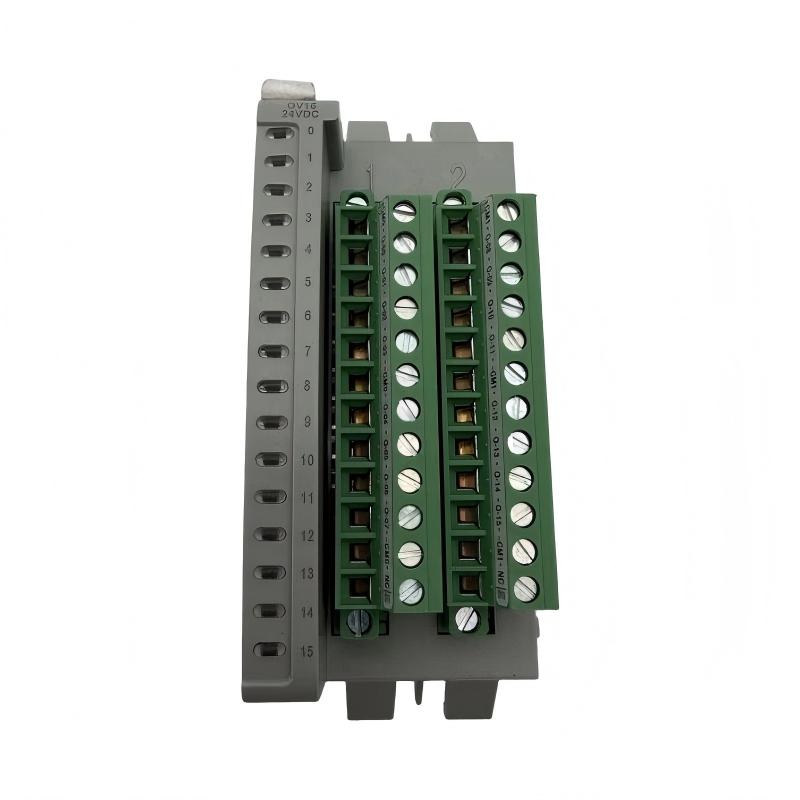
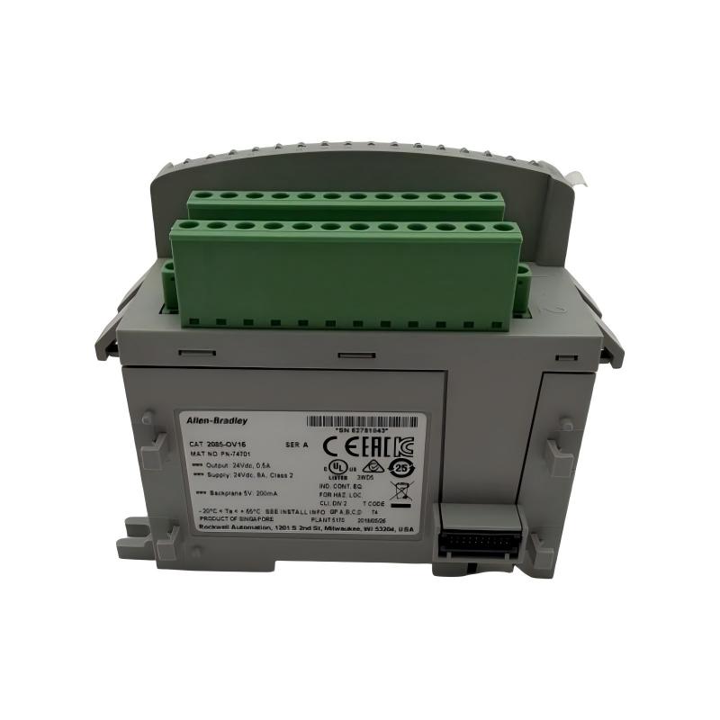
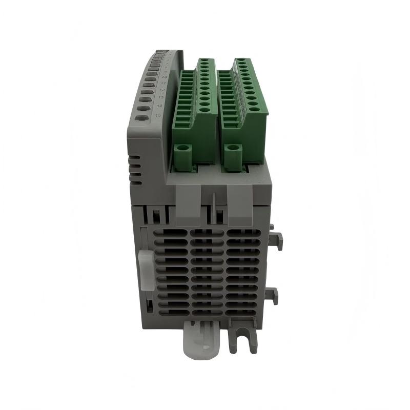
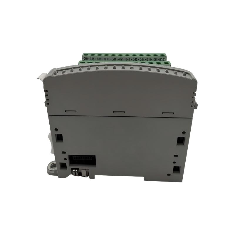
- Allen Bradley
- 2085-OV16
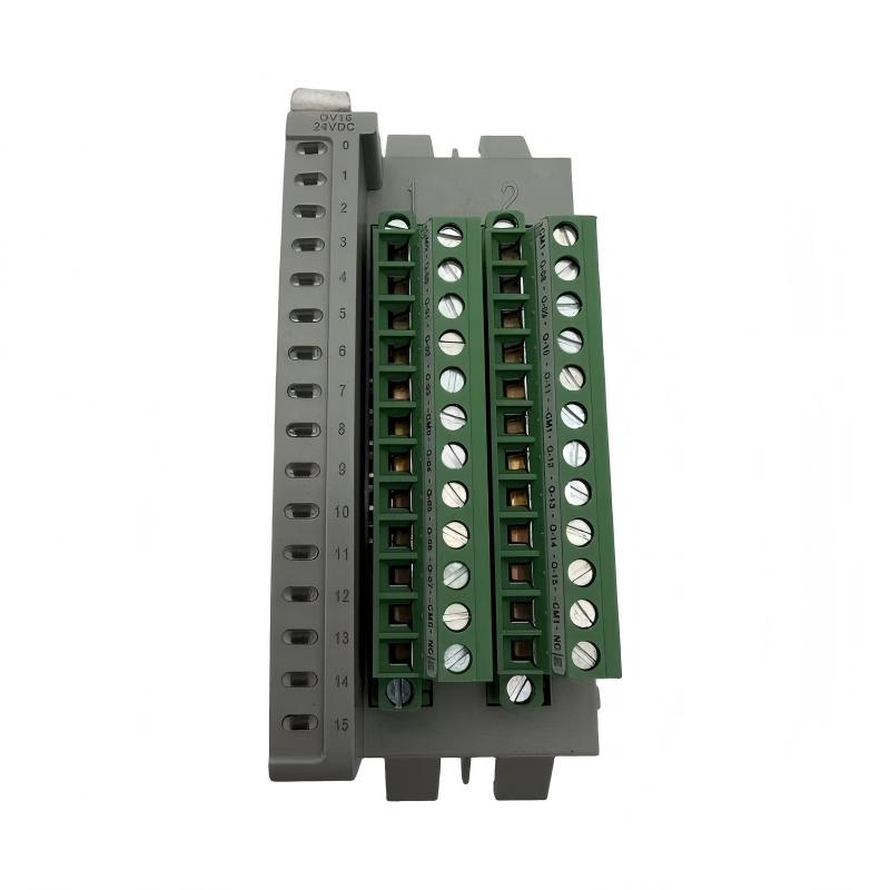
- Micro800 16-Point Sink Current Output Module
- USA
- 90 x 44.5 x 87 mm
- 0.22 kg
- Xiamen, China
- New & In Stock
- T/T, PayPal, Western Union
- 1 Year
- 1-3 Working Days
- DHL, UPS, TNT, FedEx and EMS.
- 24-Hour Service
- COO
- 7
Our advantage

Global Logistics
We have a 10-year logistics and express cooperation agreement, so our products can be shipped to any place in the world.

Brand new and original
Our products are imported in bulk from the place of origin. Because of the cooperative relationship, our products are all original and 100% new.

24-hour service
We provide 7*24 hours service to our customers. We will be there whenever you need us.

Price advantage
All our products are priced very favorably because we have our own warehouse and supply.
| Company Information | |||
| [email protected] | |||
| Mobile | +8615980777398 | ||
| +8615980777398 | |||
| 15980777398 |
1. Product Overview
The Allen-Bradley 2085-OV16 is a 16-point digital output expansion module designed for compatible Micro800 programmable controller systems. Manufactured by Rockwell Automation, this module enables a controller to operate external industrial devices through discrete 12/24 V DC output signals.
As part of the Bulletin 2085 expansion I/O family, the 2085-OV16 is designed for applications that require multiple output points in a compact control system. It provides 16 sinking DC outputs, individual channel status indicators, and isolated I/O circuitry. These features make it suitable for controlling compatible indicators, relay coils, solenoids, and other DC loads within the specified electrical limits.
The module is commonly considered for machine automation, packaging equipment, conveyor systems, assembly lines, and other industrial applications that use programmable logic to coordinate discrete equipment functions. By adding output capacity to a compatible controller, it allows engineers to control more devices without redesigning the entire control architecture.
For industrial automation maintenance teams and spare-parts buyers, the 2085-OV16 is a relevant component when expanding or maintaining a Micro800-based installation. Before purchasing a replacement, users should verify the exact model number, controller compatibility, output wiring arrangement, load requirements, and physical installation conditions.
2. Technical Specifications
| Parameter | Specification |
|---|---|
| Brand | Allen-Bradley |
| Manufacturer | Rockwell Automation |
| Model | 2085-OV16 |
| Product Type | Digital Output Expansion Module |
| Product Family | Micro800 / Bulletin 2085 Expansion I/O |
| Number of Outputs | 16 sinking outputs |
| Output Type | DC digital sink output |
| Nominal Output Voltage | 24 V DC |
| Operating Voltage Range | 10–30 V DC |
| Maximum On-State Current | 0.5 A per output at 30 V DC |
| Maximum Total Module Current | 8 A |
| Maximum On-State Voltage Drop | 1.0 V DC at 0.5 A |
| Maximum Off-State Leakage Current | 1 mA at 30 V DC |
| Maximum Bus Current Draw | 200 mA at 5 V DC |
| Maximum Power Dissipation | 5 W |
| Status Indicators | 16 yellow channel indicators |
| Isolation | Channel-to-system isolation |
| Continuous Isolation Voltage | 50 V |
| Power Supply | 24 V DC, Class 2, as specified for the module |
| Operating Temperature | -20 to 65°C (-4 to 149°F), subject to installation conditions |
| Dimensions | 90 × 44.5 × 87 mm, as supplied |
| Weight | 0.22 kg, as supplied |
| Typical Applications | Discrete machine control, actuator switching, industrial equipment |
| Product Status | Active, according to the manufacturer’s product listing |
Note: The manufacturer’s published dimensions are 44.5 × 90 × 87 mm (H × W × D). The supplied listing uses 90 × 44.5 × 87 mm. Electrical ratings depend on the specified operating conditions and wiring configuration. Check the official installation instructions before connecting loads.
3. Main Functions and Working Principle
3.1 Control of External DC Loads
The primary function of the 2085-OV16 is to switch compatible DC loads according to commands from a connected Micro800 controller. Each output point corresponds to a control signal in the controller application.
Typical loads may include compatible relay coils, indicator lights, solenoid valves, and other industrial devices designed for the module’s voltage and current ratings.
For example, a controller can use one output to activate a pneumatic valve, another to illuminate a machine status indicator, and additional outputs to coordinate different stages of a production sequence.
The module executes the electrical switching function, while the controller program determines when each output should turn on or off.
3.2 Understanding Sinking Output Operation
The 2085-OV16 uses a sinking output configuration. In a typical DC circuit, the load is connected between the positive DC supply and the module output. When an output is activated, the module provides the current path toward the DC common, allowing current to flow through the load.
This arrangement is commonly described as a sinking output because the output switches the current path toward the lower-potential side of the circuit.
Correct operation requires compatible field-device wiring. Engineers should confirm load polarity, supply voltage, common connections, and the load’s current requirements before commissioning.
A sourcing output module uses a different current-flow arrangement. Although sourcing and sinking modules may have similar physical dimensions and point counts, they are not automatically interchangeable.
3.3 Sixteen Independent Output Points
The 2085-OV16 provides 16 sinking output points for controlling multiple devices. This point count can be useful in machines where several actuators and indicators must be controlled independently.
For instance, a packaging machine may use separate outputs for product transfer, valve operation, alarm indication, and auxiliary mechanisms. The controller can coordinate these outputs according to sensor feedback and programmed operating sequences.
The number of available points does not mean every output can operate at its maximum current simultaneously without restriction. The total module current limit and other electrical specifications must be considered when designing the load distribution.
3.4 Output Status Monitoring
The module includes 16 yellow channel indicators. These LEDs help technicians identify which output channels are active during installation, commissioning, and troubleshooting.
If the controller program commands an output on, the corresponding indicator can help verify the module’s channel status. Technicians can then compare this indication with the actual load response.
An illuminated output indicator does not necessarily prove that the field device has operated correctly. Wiring faults, damaged loads, insufficient power, or mechanical problems may still prevent the equipment from responding as intended.
3.5 Electrical Isolation and Circuit Protection Considerations
The module provides channel-to-system isolation with a specified continuous isolation voltage of 50 V. This helps define the electrical separation between the I/O circuitry and the system.
Isolation does not eliminate the need for correct grounding, appropriate power distribution, or protection against overcurrent and inductive voltage transients. External loads should be selected and wired in accordance with the manufacturer’s requirements.
For inductive loads such as relay coils and solenoid valves, suitable suppression components may be required to reduce switching transients. Their selection should be based on the load characteristics and applicable installation instructions.
4. Role in a Micro800 Automation System
The 2085-OV16 functions as an output interface between a compatible Micro800 controller and external DC devices. The controller executes the application program and determines the required output states, while the module switches the associated field circuits.
A typical system may include the following components:
- Micro800 controller: Executes the machine-control program and manages supported expansion I/O.
- 2085-OV16 output module: Provides 16 sinking DC output points.
- Digital input modules: Receive signals from sensors, push buttons, and limit switches.
- Field sensors: Detect machine position, product presence, and operating conditions.
- Relays and contactors: Provide suitable switching interfaces for compatible loads where required.
- Solenoid valves: Control pneumatic or hydraulic functions when their electrical characteristics are compatible.
- Indicator lights and alarms: Communicate machine status and fault conditions.
- 24 V DC power supply: Supplies suitable power to the field circuits.
- HMI or operator panel: Displays operating states and allows operators to issue commands when included in the system.
- Terminal blocks and field wiring: Connect the module outputs to external equipment.
The complete system must be designed around the selected controller’s expansion capabilities, the module’s output ratings, and the actual load requirements. A separate output interface or relay may be necessary when the load exceeds the module’s limits or requires a different switching arrangement.
5. Industrial Applications
5.1 Packaging Machinery
Packaging systems often require multiple outputs to coordinate product transfer, valve operation, labeling equipment, alarms, and auxiliary mechanisms.
The 2085-OV16 can provide discrete control signals for compatible DC loads in these systems. The controller uses sensor feedback and sequence logic to determine when each output should operate.
This arrangement supports repeatable machine cycles and coordinated equipment operation.
5.2 Conveyor and Material Handling Systems
Conveyor systems may use output signals to control small actuators, indicators, relay interfaces, and other compatible devices associated with product movement.
The module can work with a Micro800 controller to coordinate transfer points, sorting mechanisms, and equipment status indicators. The motor or actuator interface must be selected according to its electrical rating; large motors should not be connected directly unless the load is explicitly within the module’s specifications.
5.3 Assembly Equipment
Automated assembly machines use discrete outputs to control mechanisms that position, clamp, release, or transfer components.
The 2085-OV16 can switch compatible DC loads based on the controller’s sequence logic. When combined with digital input modules, it allows the controller to issue commands and monitor feedback from the assembly process.
5.4 Pneumatic Automation
Pneumatic machinery often uses solenoid valves to control cylinders and air circuits. Where the valve coil’s voltage and current requirements are within the output module’s ratings, the 2085-OV16 can be used to control compatible valve circuits.
Engineers should verify steady-state current, inrush characteristics, inductive suppression requirements, and the total output current before assigning a valve to a channel.
5.5 Industrial Equipment and Utility Systems
The module may also be used in compact industrial skids, auxiliary equipment, small process systems, and general-purpose machinery requiring multiple discrete outputs.
Examples include status indication, relay-interface control, and switching of compatible DC actuators. Its suitability depends on environmental conditions, load characteristics, controller compatibility, and the application’s reliability requirements.
6. Installation and System Integration
6.1 Verify Controller Compatibility
Before installing the 2085-OV16, confirm that the target Micro800 controller supports the module and the intended expansion configuration. Review the controller model, supported module count, firmware requirements, and installation documentation.
Do not assume that every Micro800 controller supports the same expansion capacity or hardware arrangement.
6.2 Confirm Load Voltage and Current
Check the rated voltage and current of each field load before assigning it to an output point. The module’s specified operating voltage range is 10–30 V DC, and the maximum on-state current is 0.5 A per output under the specified conditions.
The maximum total module current is 8 A. The design should account for the combined load current, simultaneous switching, supply capacity, and any applicable derating requirements.
If a load exceeds the permitted ratings, use an appropriate external switching interface rather than connecting it directly to the module.
6.3 Follow the Sinking Output Wiring Diagram
The output circuit must follow the module’s specified sinking arrangement. In a typical circuit, the positive supply feeds the load and the module output switches the return path toward the DC common.
Before applying power, check polarity, common-terminal connections, conductor identification, and the wiring of each output channel. Incorrect wiring may prevent normal operation or damage connected equipment.
6.4 Select Suitable Conductors and Terminal Settings
The manufacturer’s installation instructions specify conductor sizes and terminal screw requirements. Use suitable copper conductors and follow the specified insulation-stripping length and terminal torque.
Avoid excessive tightening, which may damage terminals, and ensure that conductors are securely clamped. Label all output wires so maintenance personnel can trace each channel to its field device.
6.5 Account for Inductive Loads
Relays, solenoids, and other inductive loads can generate voltage transients when switched off. Depending on the device and circuit design, suitable suppression components may be needed.
Follow the load manufacturer’s recommendations and the module installation instructions when selecting suppression components. Verify that any external interface is appropriate for the switching frequency and operating conditions.
6.6 Test Each Output Point
After wiring, test the outputs individually under controlled conditions. Confirm that the controller program commands the intended channel, that the status indicator responds as expected, and that the connected field device operates correctly.
Check for unexpected output states, incorrect load assignments, loose wiring, and supply-voltage problems before returning the machine to production.
6.7 Maintain Application Records
Keep an updated I/O list, wiring diagram, controller project backup, and module catalog information. These records help engineers troubleshoot failures and replace components with less risk of wiring or configuration errors.
Standard output modules should not be used as substitutes for safety-rated outputs in safety-critical applications. Required safety functions must be implemented with appropriately rated equipment and validated safety procedures.
7. Compatible and Related System Components
The following components represent typical categories and related models that may be considered in a Micro800 automation system. Compatibility depends on the controller, wiring design, firmware, and electrical requirements.
| Model / Component | Type | Function |
|---|---|---|
| Compatible Micro800 controller | Programmable controller | Executes the application logic and manages supported expansion modules |
| 2085-OV16 | 16-point sinking DC output module | Switches compatible DC loads |
| 2085-OB16 | 16-point sourcing DC output module | Provides sourcing outputs for compatible DC loads |
| 2085-IQ16 | 16-point DC digital input module | Receives discrete input signals |
| 2085-IQ32T | 32-point DC digital input module | Provides a higher number of digital input points |
| 2085-OW16 | Relay output module | Provides relay-based output switching in compatible applications |
| 2085-IA8 | AC digital input module | Receives compatible AC input signals |
| 24 V DC power supply | Industrial power supply | Supplies power to compatible field circuits |
| Relay or interface module | External switching interface | Interfaces with loads requiring different electrical characteristics |
| HMI or operator panel | Operator interface | Displays machine status and accepts operator commands |
This table is a general system-planning reference. It does not guarantee that all listed components can be installed together in every configuration. Verify the selected controller’s expansion limits and each component’s technical requirements before purchasing.
8. Alternative Models and Replacement Considerations
When evaluating a replacement or alternative, the output circuit type is one of the most important factors. Output modules with the same number of channels can use different switching arrangements and may require different field wiring.
| Model | Output Type | Main Consideration |
|---|---|---|
| 2085-OV16 | 16-point sinking DC output | Reference model for this product |
| 2085-OB16 | 16-point sourcing DC output | Alternative when sourcing output operation is required and the system supports it |
| 2085-OW16 | Relay output | Consider for compatible applications that require relay switching; verify load ratings |
| 2085-IQ16 | 16-point DC digital input | Input module, not a direct output replacement |
| 2085-IQ32T | 32-point DC digital input | Higher input-point count, but a different function |
The 2085-OB16 is the closest functional comparison because it also provides 16 DC output points, but its sourcing output arrangement differs from the 2085-OV16. The two models should not be substituted without reviewing the field wiring and electrical requirements.
For direct replacement, verify the exact catalog number, module condition, controller compatibility, wiring configuration, and output load ratings. Also check whether the application depends on specific output behavior or timing characteristics.
9. Key Advantages of the 2085-OV16
Sixteen DC Output Channels
The module provides 16 sinking outputs, enabling a compatible Micro800 controller to operate multiple field devices from a compact expansion module.
Defined Electrical Ratings
Specified voltage and current limits help engineers evaluate load compatibility and design the output circuits appropriately.
Individual Channel Indicators
The 16 yellow channel indicators support visual checks during commissioning and routine troubleshooting.
Compact Expansion Design
The module’s physical format supports integration into compatible Micro800 expansion installations where panel space is important.
Isolated I/O Architecture
Channel-to-system isolation helps define the module’s electrical separation, while proper grounding and wiring remain essential for safe and reliable operation.
Practical Maintenance and Spare-Part Planning
The clearly identified catalog number helps equipment owners specify the correct replacement and maintain an appropriate inventory of automation components.
10. Frequently Asked Questions
Q1: What is the Allen-Bradley 2085-OV16?
The 2085-OV16 is a 16-point digital output expansion module for compatible Micro800 systems. It provides sinking DC outputs for controlling compatible external loads.
Q2: Is the 2085-OV16 a sinking or sourcing output module?
It is a sinking output module. In a typical DC circuit, the load is connected to the positive supply, and the output switches the current return path toward the DC common.
Q3: What voltage does the 2085-OV16 support?
Its specified operating voltage range is 10–30 V DC, with 24 V DC as the nominal operating voltage.
Q4: What is the maximum current per output?
The maximum on-state current is 0.5 A per output at 30 V DC under the specified conditions. The maximum total module current is 8 A. Both limits must be considered during system design.
Q5: Can the module drive solenoid valves?
It can control compatible DC solenoid valve coils when their electrical requirements fall within the module’s ratings. Check the coil’s current, inrush characteristics, and suppression requirements before connecting it.
Q6: Does the 2085-OV16 support AC loads?
The 2085-OV16 is a DC output module. It should not be used to switch AC loads directly. Select a suitable interface or a module designed for the intended load type.
Q7: What is the difference between the 2085-OV16 and 2085-OB16?
The 2085-OV16 uses sinking outputs, while the 2085-OB16 uses sourcing outputs. The correct model depends on the field-device wiring arrangement and the required current-flow configuration.
Q8: What are the dimensions and weight of the 2085-OV16?
The supplied listing gives dimensions of 90 × 44.5 × 87 mm and a weight of 0.22 kg. The manufacturer’s published dimensions are 44.5 × 90 × 87 mm in height × width × depth order, with an approximate shipping weight of 220 g.
Q9: How can technicians troubleshoot an output that does not operate?
Check the controller command, channel status indicator, DC supply voltage, output wiring, load condition, and common connections. Verify that the load does not exceed the module’s electrical limits before replacing the module.
Q10: Is the 2085-OV16 still an active product?
The manufacturer’s product listing identifies the 2085-OV16 as active. Confirm current availability, hardware details, and delivery conditions with the supplier before ordering.
11. Purchasing and Maintenance Recommendations
When sourcing the Allen-Bradley 2085-OV16, provide the complete catalog number and explain whether the module is intended for a new Micro800 installation, an expansion project, or replacement of a failed unit.
For replacement orders, compare the original module label with the new product listing. Confirm the sinking output arrangement, controller compatibility, output voltage, load current, and terminal wiring before installation.
Industrial automation buyers should also verify the unit’s condition, warranty terms, packaging, and included accessories. If the module will be used in a critical production process, keeping a suitable spare can help reduce downtime caused by an unexpected failure.
During routine maintenance, inspect wiring connections, check the status indicators, verify field-load operation, and review any controller diagnostics. Keep the I/O list and wiring diagrams updated so technicians can identify the correct output channel quickly.
Before removing or installing the module, follow the applicable electrical isolation and safety procedures. Do not handle live wiring or change output connections while the equipment is energized unless the system’s documented procedures specifically permit the operation.
12. Conclusion
The Allen-Bradley 2085-OV16 Micro800 16-Point Sink Output Module is designed to provide discrete DC output control in compatible Micro800 automation systems. Its 16 sinking output points, channel status indicators, and defined electrical ratings make it suitable for many compact industrial control applications.
The module can support packaging equipment, conveyor systems, assembly machinery, pneumatic automation, and other installations that require multiple discrete output signals. Successful integration depends on verifying the controller configuration, supply voltage, load current, wiring arrangement, and total module current.
For industrial automation equipment buyers and maintenance engineers, the 2085-OV16 is a practical component to consider when expanding or maintaining a compatible control system. Careful model verification and correct electrical installation help support dependable operation and simplify future maintenance.