

ProductPRODUCT
Featured products
Contact Us
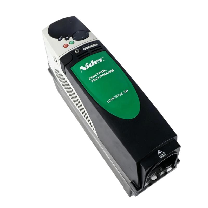
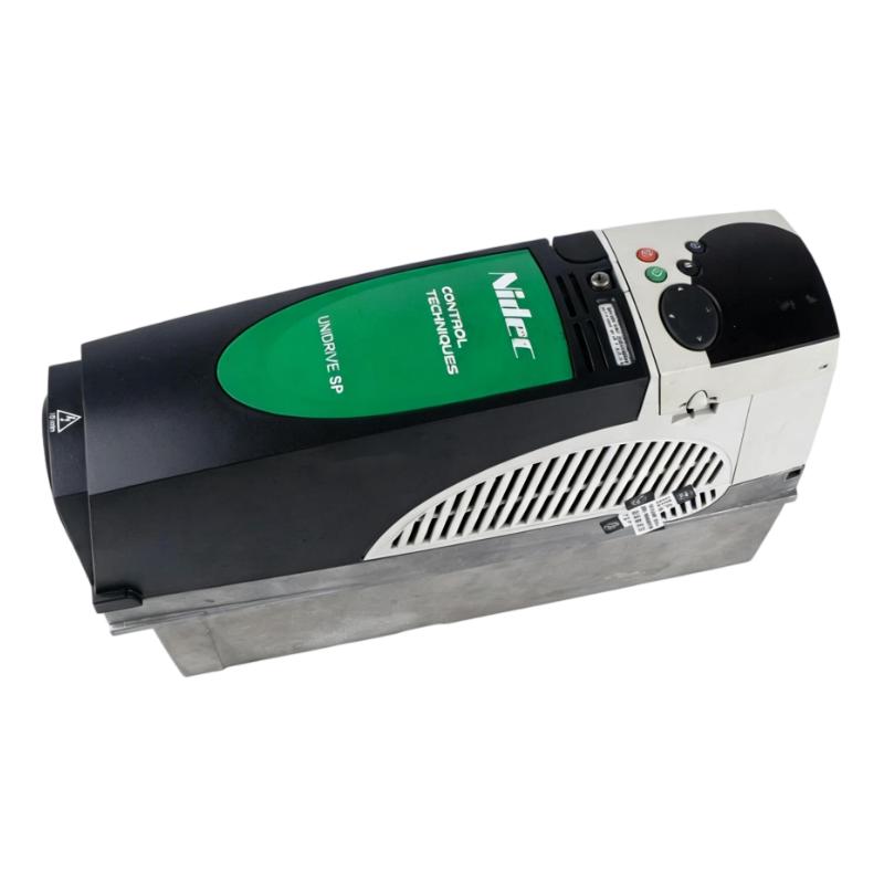
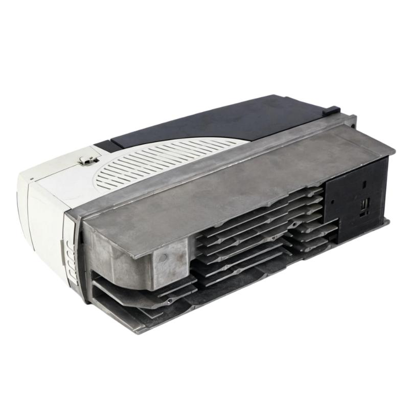
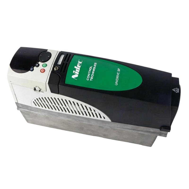
- Emerson
- SP1406
- AC Drive
- USA
- 368 × 100 × 219 mm
- 1.4 kg
- Xiamen, China
- New & In Stock
- T/T, PayPal, Western Union
- 1 Year
- 1-3 Working Days
- DHL, UPS, TNT, FedEx and EMS.
- 24-Hour Service
- COO
- 6
Our advantage

Global Logistics
We have a 10-year logistics and express cooperation agreement, so our products can be shipped to any place in the world.

Brand new and original
Our products are imported in bulk from the place of origin. Because of the cooperative relationship, our products are all original and 100% new.

24-hour service
We provide 7*24 hours service to our customers. We will be there whenever you need us.

Price advantage
All our products are priced very favorably because we have our own warehouse and supply.
| Company Information | |||
| [email protected] | |||
| Mobile | +8615980777398 | ||
| +8615980777398 | |||
| 15980777398 |
Product Overview
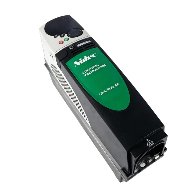
The Emerson SP1406 Unidrive SP Series AC Drive is a universal AC and servo drive for industrial motor-control applications requiring adjustable speed, torque regulation and configurable control behavior. It belongs to the Unidrive SP platform, which supports open-loop and closed-loop induction motor control, V/Hz operation, rotor flux control and compatible servo motor applications.
The SP1406 operates from a three-phase 380–480 V AC supply and has continuous output-current ratings of 9.5 A in Heavy Duty mode and 11 A in Normal Duty mode. These ratings are relevant when matching the drive to motor current requirements and the load’s overload characteristics. The model is commonly associated with applications rated up to 4.0 kW Heavy Duty or 5.5 kW Normal Duty at 400 V, subject to the applicable rating conditions.
Unlike a basic fixed-speed starter, the SP1406 allows the motor response to be configured around the machine’s operating cycle. Speed references, ramp settings, control mode and optional feedback or communication modules can be selected to suit the application. Its integrated I/O and onboard Modbus RTU interface also support integration with compatible machine controllers and supervisory systems.
Technical Specifications
| Parameter | Specification |
|---|---|
| Manufacturer | Emerson / Control Techniques |
| Model | SP1406 |
| Product Series | Unidrive SP |
| Product Type | Universal AC and Servo Drive |
| Drive Frame Size | Size 1 |
| Input Supply | Three-phase AC |
| Input Voltage | 380–480 V AC |
| Input Frequency | 48–65 Hz |
| Heavy Duty Continuous Output Current | 9.5 A |
| Normal Duty Continuous Output Current | 11 A |
| Typical Motor Power at 400 V, Heavy Duty | 4.0 kW |
| Typical Motor Power at 400 V, Normal Duty | 5.5 kW |
| Typical Motor Power at 460 V, Heavy Duty | 5 hp |
| Typical Motor Power at 460 V, Normal Duty | 7.5 hp |
| Supported Control Modes | V/Hz, open-loop vector, rotor flux control, closed-loop induction control and compatible servo control |
| Digital Inputs | 7 |
| Analog Inputs | 3 |
| Digital Outputs | 3 |
| Analog Outputs | 2 |
| Relay Outputs | 1 |
| Onboard Communication | Modbus RTU |
| Option Slots | 3 |
| Enclosure Protection | IP20 |
| Optional Expansion | Compatible Unidrive SP communication, I/O and feedback modules |
| Dimensions | 368 × 100 × 219 mm |
| Weight | 1.4 kg |
Product Features
- Dual-duty current ratings: Provides 9.5 A Heavy Duty and 11 A Normal Duty continuous output-current ratings for different application load profiles.
- Universal motor-control platform: Supports multiple control methods for compatible induction and servo motor applications.
- Three-phase 380–480 V operation: Fits industrial power systems within the specified voltage range.
- Integrated digital and analog I/O: Supports external control signals, references and configured monitoring functions.
- Onboard Modbus RTU: Allows supported drive data to be exchanged with compatible automation equipment.
- Three expansion slots: Accommodates compatible option modules for additional communication, feedback or application functions.
- Configurable speed response: Allows operating references, speed limits and ramp behavior to be adjusted to the machine.
- Feedback-based control options: Supports compatible feedback interfaces when the application requires closed-loop operation.
- Diagnostic capability: Provides status and fault information for commissioning and maintenance.
- Application adaptability: Supports different machine requirements through control-mode selection and parameter configuration.
Working Principle
The SP1406 converts three-phase AC input power into a controlled output for the connected motor. The power stage regulates motor operation according to the selected control mode, configured motor data and incoming speed or torque references. The chosen control method determines how the drive manages output behavior and responds to changing load conditions.
In Heavy Duty operation, the SP1406 is rated for 9.5 A continuous output current; in Normal Duty operation, it is rated for 11 A. The appropriate duty depends on the motor’s current demand, overload requirements and operating profile. Engineers should assess the actual load and applicable rating conditions rather than selecting the drive based only on nominal motor power.
For open-loop applications, the drive controls motor output without relying on an external speed-feedback device. Where a supported closed-loop mode is required, a compatible feedback interface and correctly configured feedback device may be necessary. The selected control method, motor parameters and feedback arrangement must work together for the intended response.
Acceleration, deceleration and stopping parameters affect how the motor responds to command changes. If a machine has high inertia or frequent stopping cycles, the braking arrangement and DC-bus behavior should also be evaluated. Fault indications and operating records help maintenance personnel distinguish electrical supply problems, configuration issues, excessive load and feedback-related faults.
Role in an Industrial Motor Control Architecture
The SP1406 serves as the motor-control layer between the industrial power supply, automation controller and driven machine. It processes operating commands, regulates motor output and returns supported status or diagnostic information to the wider control system.
| System Component | Function | Relationship to the Drive |
|---|---|---|
| Three-Phase AC Supply | Provides electrical input power | Feeds the drive through appropriately rated isolation and protective devices |
| AC Induction Motor | Converts electrical power into mechanical motion | Receives the controlled output from the drive |
| Compatible Servo Motor | Provides controlled motion where supported | Requires a suitable control mode and compatible configuration |
| PLC or Machine Controller | Coordinates machine sequencing | Sends supported run commands, references and enable signals |
| Analog Reference Source | Supplies a variable speed or process reference | Connects to a configured compatible analog input |
| Digital Control Circuit | Carries run, enable and interlock signals | Uses the drive’s supported digital I/O |
| Encoder or Feedback Device | Supplies speed or position feedback | Requires a compatible feedback interface and supported control mode |
| Modbus RTU Master | Exchanges supported drive information | Communicates through the onboard serial interface |
| Braking Arrangement | Manages regenerated energy during applicable stopping cycles | Must be selected according to the load and drive configuration |
| Supervisory System | Displays operating status and diagnostic data | Uses supported communication or controller-mapped signals |
Industrial Applications
| Application | Operating Requirement | Role of the SP1406 |
|---|---|---|
| Industrial Conveyors | Coordinate speed with material flow and machine sequencing | Regulates motor speed through configured references and operating limits |
| Pumps and Fluid Handling Systems | Adapt motor operation to changing process demand | Supports variable-speed operation when the motor and pump are appropriately matched |
| Fans and Blowers | Adjust airflow through motor-speed control | Changes motor operation in response to the required speed reference |
| Extrusion Equipment | Maintain controlled motor behavior under changing process loads | Applies configured motor-control parameters and limits |
| Winding and Unwinding Machinery | Coordinate motor speed or torque with line operation | Supports suitable configured speed or torque-control applications |
| Packaging Machinery | Match motor response to production timing | Executes programmed references and acceleration or deceleration settings |
| Hoisting and Material Handling | Manage motor response during motion and stopping | Requires suitable drive configuration, braking design and application-specific safety measures |
| General Industrial Machinery | Coordinate motor control with automated sequences | Executes compatible commands and supplies status and fault information |
Installation and Maintenance
- Verify the model designation: Confirm that the drive is an SP1406 and that its electrical ratings match the intended application.
- Check the incoming supply: Verify the three-phase voltage and frequency against the unit’s rating information before connecting power.
- Inspect the drive assembly: Check accessible terminals, connectors and the enclosure for visible damage, contamination or signs of overheating.
- Provide suitable ventilation: Follow the specified mounting clearances and cooling requirements to manage heat inside the control panel.
- Verify protective grounding: Ensure the protective-earth connection follows the electrical design and applicable installation requirements.
- Match the duty rating to the load: Compare the motor’s rated current and overload requirements with the 9.5 A Heavy Duty and 11 A Normal Duty ratings.
- Check motor and feedback wiring: Verify output connections, conductor sizing, phase assignment and any installed feedback-device wiring.
- Review control I/O assignments: Confirm run commands, stop signals, analog references, relay outputs and machine interlocks against the electrical drawings.
- Configure motor parameters: Enter the required motor data and confirm that the selected control mode is suitable for the motor and application.
- Evaluate stopping requirements: Review deceleration settings and the braking arrangement where the machine has high inertia or frequent stopping cycles.
- Test communication and control functions: Verify Modbus RTU settings, command response, feedback operation where applicable and configured fault handling.
- Record commissioning results: Document the duty selection, motor data, parameter settings, option modules, fault history and functional test results.
Compatible System Components
| Component | Function | Compatibility Consideration |
|---|---|---|
| Compatible AC Induction Motor | Produces mechanical output | Verify voltage, current and control requirements against the drive |
| Supported Servo Motor | Provides controlled motion in suitable applications | Confirm the required servo-control configuration and motor compatibility |
| PLC or Machine Controller | Executes machine logic | Confirm supported command signals and interface arrangements |
| Analog Reference Source | Supplies a speed or process reference | Match signal type and scaling to the configured input |
| Encoder or Feedback Device | Provides speed or position information | Requires a compatible feedback option and supported device |
| Modbus RTU Master | Exchanges supported drive data | Configure the serial settings and supported data mapping |
| Communication Option Module | Adds another supported network interface | Verify the exact module, protocol and drive compatibility |
| Braking Components | Support applicable deceleration requirements | Select according to the load and drive’s braking configuration |
| Upstream Protective Device | Protects the input supply circuit | Select according to the electrical installation design |
Recommended Related Models
| Model | Product Type | Relationship | Selection Consideration |
|---|---|---|---|
| Emerson SP1404 | Unidrive SP AC Drive | Lower-current model in the same series | Compare its 5.8 A Heavy Duty and 6.9 A Normal Duty ratings with the required motor current |
| Emerson SP1405 | Unidrive SP AC Drive | Lower-current model in the same series | Compare its 7.6 A Heavy Duty and 8.8 A Normal Duty ratings with the load profile |
| Emerson SP2401 | Unidrive SP AC Drive | Related model from the Size 2 group | Compare current ratings, frame size and installation requirements before selection |
| Emerson SP2402 | Unidrive SP AC Drive | Higher-rated model in the Size 2 group | Evaluate when the application requires a different current capacity or frame configuration |
Key Advantages
- Provides 9.5 A Heavy Duty and 11 A Normal Duty continuous output-current ratings.
- Supports multiple control modes for compatible induction and servo motor applications.
- Includes integrated digital, analog and relay I/O.
- Offers onboard Modbus RTU communication and three option slots.
- Supports compatible feedback and communication expansion for specialized applications.
- Supplies status and fault information for commissioning and troubleshooting.
Technical FAQs
How should the SP1406 be evaluated for an application with frequent load peaks?
Review the motor’s current demand during starting and peak load, the required overload duration and the selected duty rating. Compare these conditions with the drive’s applicable continuous and peak-current limits, and assess whether the load cycle requires a different model or configuration.
What can cause unstable speed feedback when the SP1406 operates in a closed-loop mode?
Possible causes include incorrect feedback-device configuration, wiring or shielding problems, an incompatible feedback interface, incorrect motor data or unsuitable control tuning. Check the feedback signal and its configuration before changing speed-loop parameters.
How should braking requirements be assessed for a high-inertia machine?
Estimate the machine’s stopping frequency, inertia and required deceleration time. Then check the drive’s permitted braking arrangement and the requirements for any braking components. Confirm that the chosen stopping method can handle the expected regenerated energy without repeated overvoltage trips.
What should be checked when Modbus RTU communication works intermittently with the SP1406?
Check the serial address, baud rate, parity, stop bits and network wiring at both ends. Inspect the RS485 topology, termination and grounding arrangements where applicable, and review controller timeouts and communication errors before changing drive-control parameters.