

ProductPRODUCT
Featured products
Contact Us
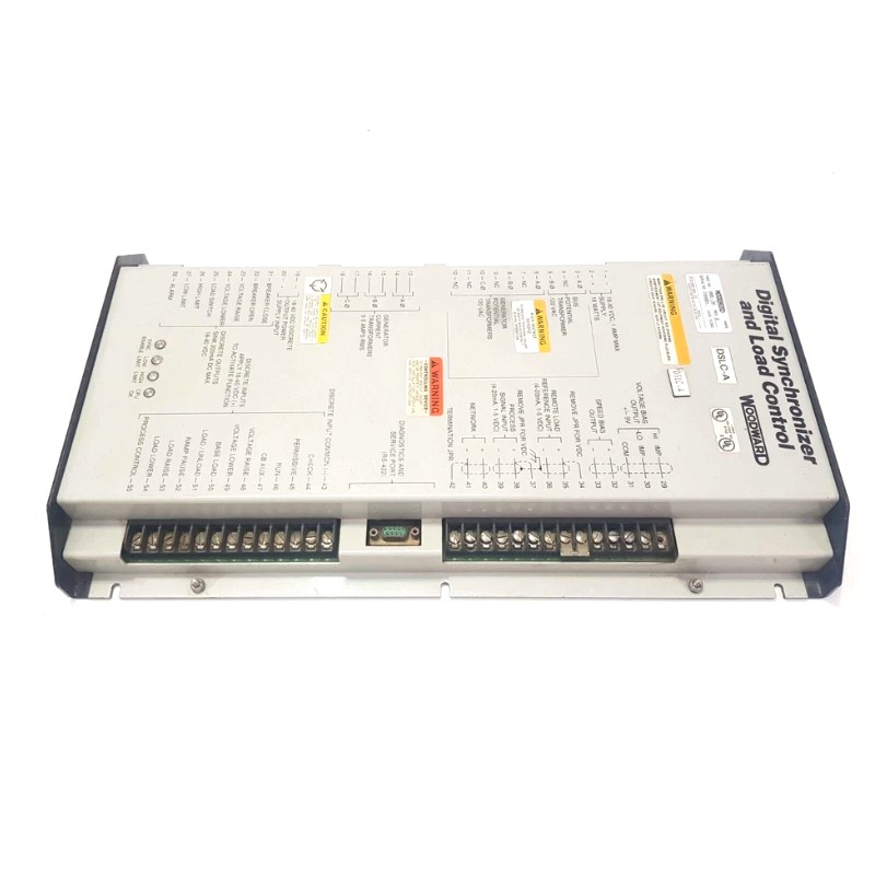
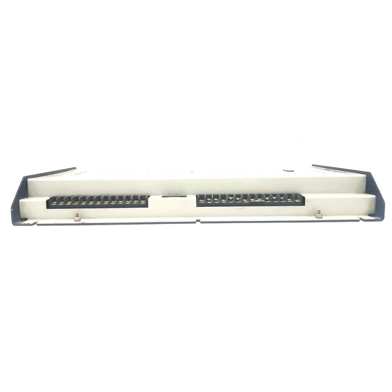
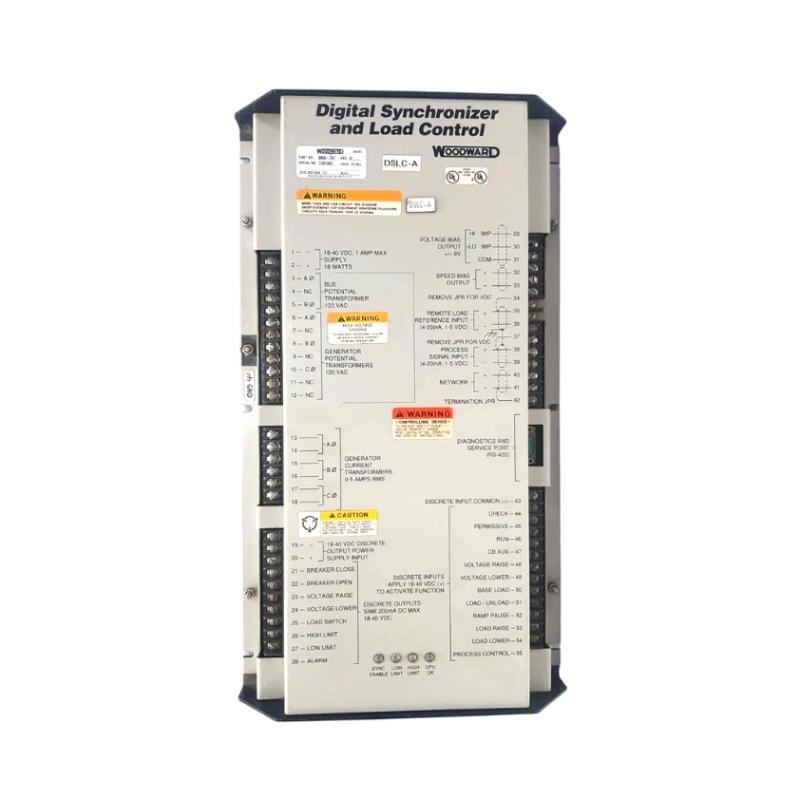
- Woodward
- 9905-976
- Overspeed Protection System
- USA
- 120 × 100 × 50 mm
- 0.8 kg
- Xiamen, China
- New & In Stock
- T/T, PayPal, Western Union
- 1 Year
- 1-3 Working Days
- DHL, UPS, TNT, FedEx and EMS.
- 24-Hour Service
- COO
- 5
Our advantage

Global Logistics
We have a 10-year logistics and express cooperation agreement, so our products can be shipped to any place in the world.

Brand new and original
Our products are imported in bulk from the place of origin. Because of the cooperative relationship, our products are all original and 100% new.

24-hour service
We provide 7*24 hours service to our customers. We will be there whenever you need us.

Price advantage
All our products are priced very favorably because we have our own warehouse and supply.
| Company Information | |||
| [email protected] | |||
| Mobile | +8615980777398 | ||
| +8615980777398 | |||
| 15980777398 |
Product Overview
The Woodward 9905-976 Overspeed Protection System is an industrial machinery protection device designed to monitor rotational speed and initiate protective action when an engine, turbine, or other rotating machine exceeds its configured operating limit.
The 9905-976 belongs to the Woodward ProTech 203 product family. Overspeed protection is an essential part of machinery safety because excessive rotational speed can cause severe mechanical stress, equipment damage, and potentially dangerous operating conditions.
Unlike a conventional speed controller, an overspeed protection system focuses on detecting abnormal speed conditions and initiating a shutdown or trip response. It works alongside the machinery’s normal control system but serves a separate protective function.
The 9905-976 is a 120 VAC/DC supply configuration. The ProTech 203 architecture uses three protection units, identified as Unit A, Unit B, and Unit C. Each unit contributes to the overall protective arrangement. The precise voting logic, trip behavior, and external wiring must be confirmed against the system’s installed configuration and applicable Woodward documentation.
This model is relevant to industrial facilities that operate turbines, engines, compressors, and other high-speed rotating equipment. It is particularly important in applications where independent overspeed protection is required as part of the machinery safety design.
Technical Specifications
| Parameter | Specification |
|---|---|
| Brand | Woodward |
| Model | 9905-976 |
| Product Family | ProTech 203 |
| Product Type | Overspeed Protection System |
| Main Function | Rotational speed monitoring and overspeed trip protection |
| Power Supply Configuration | 120 VAC/DC |
| Supply Range | 88–132 VAC or 90–150 VDC |
| System Architecture | Three protection units: A, B, and C |
| Speed Detection | Speed signals from compatible magnetic pickup sensors |
| Protection Function | Configurable overspeed detection and trip |
| Operating Role | Independent machinery protection |
| Typical Equipment | Engines, turbines, and rotating machinery |
| Dimensions Provided | 120 × 100 × 50 mm |
| Weight Provided | 0.8 kg |
Note: The dimensions and weight are supplied listing values, not independently confirmed overall ProTech 203 enclosure dimensions. Verify whether they describe an individual component or the complete protection assembly before using them for shipping or installation.
Function and Working Principle
The Woodward 9905-976 monitors machine speed and compares the measured value with configured protection limits. If the measured speed reaches an overspeed trip threshold, the protection system initiates the designated trip action.
Its operation can be understood through several functional stages.
1. Speed Signal Acquisition
The protection system receives rotational-speed information from compatible speed-sensing devices, commonly magnetic pickup units (MPUs).
An MPU detects changes in the magnetic field caused by the passage of teeth or other suitable features on a rotating target. It generates an electrical signal whose frequency corresponds to rotational speed.
The protection equipment processes this signal to determine the machine’s operating speed.
Sensor installation and signal quality are important. Incorrect sensor gaps, damaged wiring, electrical interference, or unsuitable sensor characteristics can affect measurement reliability.
2. Speed Calculation
The protection units evaluate the incoming speed signals and determine whether the machine is operating within the permitted range.
The configured speed limits must correspond to the mechanical design and operating requirements of the protected machine. The trip threshold should be established by qualified machinery and safety engineers rather than selected solely from normal operating speed.
3. Overspeed Detection
When the measured speed exceeds the configured trip point, the protection system identifies an overspeed condition.
The trip function is intended to prevent a machine from continuing to operate at a speed that may exceed its safe mechanical limits.
Depending on the installed configuration, the protection arrangement may also account for sensor failure and other diagnostic conditions. The exact trip logic should be verified using the relevant product manual and system documentation.
4. Protective Output and Shutdown
Once a valid trip condition is detected, the system operates its configured protective outputs. These outputs can be connected to the machinery shutdown circuit, such as a trip relay arrangement that initiates fuel, steam, or other energy isolation.
The complete shutdown sequence depends on the turbine or engine control architecture, external relays, actuators, and wiring.
A successful trip function therefore depends not only on the protection device but also on the condition and correct operation of the entire shutdown path.
5. Independent Protection
Overspeed protection should not depend entirely on the normal speed-control system. If a governor, controller, or associated control component fails, an independent protection arrangement can provide an additional layer of safety.
The ProTech 203 is intended for this protective role. Its installation and configuration should preserve the required independence between normal control and protective shutdown functions.
Role in Industrial Control Systems
The Woodward 9905-976 is typically integrated into a machinery protection arrangement rather than used as a general-purpose PLC controller.
Its main responsibility is to detect dangerous speed conditions and provide a protective response.
Independent Machinery Protection
In turbine and engine installations, the normal control system regulates speed and load during operation. The overspeed protection system monitors speed separately and initiates a trip if the configured protection limit is exceeded.
This separation helps reduce dependence on a single control function.
Integration with Shutdown Circuits
The protection system’s outputs can be incorporated into an external shutdown circuit. Depending on the machine design, the trip signal may operate a shutdown relay, fuel shutoff mechanism, steam valve trip device, or another approved protective element.
The output wiring must be designed according to the applicable safety requirements and the product’s documented electrical characteristics.
Coordination with Control Systems
A PLC, turbine controller, or distributed control system may monitor operating information and coordinate normal process operation.
However, the protective trip function should retain the required independence. The normal control system should not be able to unintentionally override or compromise the safety function.
Alarm and Maintenance Monitoring
Protection equipment may also provide diagnostic information to assist operators and maintenance engineers. Such information can help identify sensor problems, power supply abnormalities, or protection-unit faults.
The exact available indication and communication features should be confirmed for the installed 9905-976 configuration.
Industrial Applications
The Woodward 9905-976 is intended for overspeed protection in machinery where rotational speed must remain within defined mechanical limits.
1. Steam Turbines
Steam turbines operate at high rotational speeds and require reliable protection against overspeed conditions.
An overspeed protection system monitors turbine speed and initiates a trip when the configured threshold is exceeded. The trip circuit can be connected to the turbine’s emergency shutdown arrangement.
This protection is important during load rejection, governor malfunction, or other abnormal operating conditions that could cause turbine speed to rise.
2. Gas Turbines
Gas turbines are used in power generation, industrial processes, and mechanical drive applications.
Their protection systems must respond to abnormal operating conditions that could result in excessive rotor speed. An independent overspeed protection device provides an additional safeguard alongside the normal turbine control system.
3. Diesel and Gas Engines
Large industrial engines are used in generator sets, compressors, pumps, and mechanical drive systems.
An overspeed condition can expose engine components to excessive mechanical stress. The protection system can monitor rotational speed and initiate shutdown when the configured trip condition is reached.
4. Industrial Compressors
High-speed compressors may be driven by turbines or engines. Their operation requires coordination between the driver, compressor, lubrication system, and process equipment.
Overspeed protection helps protect the prime mover and associated machinery from operating beyond permitted speed limits.
5. Power Generation Equipment
Power generation facilities depend on reliable protection systems to maintain safe operation of turbines and generator-driving equipment.
Overspeed protection is an important part of the overall turbine safety arrangement. It should be coordinated with other protective functions, including vibration, lubrication, temperature, and emergency shutdown systems.
Installation and System Integration
Correct installation is essential because the 9905-976 performs a machinery protection function. Installation and commissioning should be completed by qualified personnel familiar with the protected machine and its shutdown architecture.
1. Verify the Model and Power Supply
Before installation, confirm the complete catalog number and the required power supply.
The 9905-976 is listed in the ProTech 203 documentation as a 120 VAC/DC configuration, with a specified supply range of 88–132 VAC or 90–150 VDC.
Do not apply a supply voltage based only on the product family’s appearance or another model’s specifications. Verify the actual nameplate and documentation.
2. Install Speed Sensors Correctly
The speed-sensing arrangement must be compatible with the protection system.
For magnetic pickup installations, engineers should verify the sensor type, mechanical mounting, air gap, wiring polarity where applicable, and signal characteristics.
The sensor must provide a stable signal throughout the intended operating-speed range.
3. Plan the Wiring Arrangement
Separate sensor wiring from high-current power conductors where required. Use suitable shielding and grounding practices to reduce electromagnetic interference.
Power supply wiring, sensor inputs, trip outputs, and diagnostic connections must follow the applicable Woodward installation instructions.
Incorrect wiring can cause false alarms, unreliable measurements, or failure to initiate the intended trip response.
4. Configure the Overspeed Setpoint
The overspeed trip threshold must be established using the machine’s approved protection design.
The setting should consider the turbine or engine’s rated speed, maximum permitted speed, mechanical limitations, and relevant safety requirements.
Do not change the trip setpoint without appropriate engineering authorization and documented procedures.
5. Verify the Shutdown Circuit
The trip output must be connected to the correct external shutdown circuit.
Commissioning should verify the complete path from speed detection through trip logic and output operation to the final shutdown element.
Testing only the protection device’s front panel or internal indication is insufficient to demonstrate that the complete machinery shutdown function operates correctly.
6. Perform Functional Testing
Before the machine is placed into service, conduct the required inspection and functional tests.
Testing should verify the speed-sensing channels, power supplies, protection logic, trip outputs, alarm indications, and external shutdown circuit.
The test procedure must follow the manufacturer’s documentation and the facility’s approved machinery safety procedures.
Compatible System Components
The 9905-976 operates as part of a larger protection and machinery-control arrangement.
| Component | Function | Integration Considerations |
|---|---|---|
| Magnetic pickup sensor | Measures rotational speed | Confirm sensor compatibility, mounting, and signal quality |
| Speed-sensing target | Provides a detectable rotating feature | Verify mechanical condition and sensor geometry |
| Shutdown relay | Transfers the trip command to the shutdown circuit | Confirm contact ratings and circuit design |
| Emergency shutdown system | Initiates machinery shutdown | Verify the complete trip path and required independence |
| Turbine or engine controller | Manages normal machinery operation | Keep normal control separate from the independent protection function |
| PLC or DCS | Provides process monitoring and coordination | Do not allow normal process logic to compromise protective functions |
| Power supply | Supplies the protection equipment | Match the 120 VAC/DC model’s documented voltage range |
| Terminal and wiring assemblies | Connect sensors, power, and trip outputs | Follow wiring diagrams, shielding, and grounding requirements |
| Operator alarm system | Displays relevant operating or fault information | Confirm available outputs and indication functions |
The components listed above describe a typical machinery protection arrangement. They are not necessarily included with the 9905-976.
Replacement Models and Selection Considerations
When replacing a Woodward overspeed protection device, engineers should compare the complete model number, supply voltage, trip logic, sensor inputs, output arrangement, and physical installation requirements.
| Related Product or Option | Selection Considerations |
|---|---|
| Woodward ProTech 203 9905-series models | Compare supply configuration, trip behavior, and unit arrangement |
| Woodward ProTech 203 models with different supply voltages | Verify the power supply requirements for all protection units |
| Other ProTech 203 configurations | Confirm enclosure type, trip logic, and electrical characteristics |
| Newer Woodward protection systems | Evaluate functionality, safety requirements, wiring, and commissioning changes |
A replacement should not be selected solely because it belongs to the same product family.
Before substitution, review:
- Complete catalog number and hardware revision.
- AC or DC supply requirements.
- Number and arrangement of protection units.
- Speed sensor type and input characteristics.
- Overspeed trip settings and configuration.
- Trip output and relay behavior.
- Shutdown circuit compatibility.
- Mounting dimensions and enclosure requirements.
- Existing wiring and maintenance procedures.
- Required safety validation and commissioning tests.
Because overspeed protection is a safety-related function, replacement and configuration changes should be reviewed and approved by qualified personnel.
Key Advantages
Dedicated Overspeed Protection
The 9905-976 is designed specifically to monitor rotational speed and initiate protective action when an overspeed condition is detected.
ProTech 203 Architecture
The product belongs to the ProTech 203 family, which uses three protection units in its system arrangement.
Defined Power Supply Configuration
The 9905-976 is identified as a 120 VAC/DC model, supporting installations designed around its specified supply range.
Integration with Machinery Shutdown Systems
Its protective function can be incorporated into an appropriate external shutdown arrangement for engines, turbines, and other rotating machinery.
Support for Critical Machinery Protection
Overspeed monitoring is important for equipment where excessive rotational speed can result in serious mechanical damage or unsafe operating conditions.
Established Industrial Protection Application
The ProTech 203 family is associated with industrial machinery protection, particularly in turbine and engine applications.
Technical FAQs
1. What is the Woodward 9905-976?
The Woodward 9905-976 is a ProTech 203 Overspeed Protection System designed to monitor rotational speed and initiate a protective trip when configured overspeed conditions are detected.
2. What is the main function of this system?
Its primary function is to protect engines, turbines, and other rotating machinery against excessive rotational speed by initiating a configured shutdown response.
3. What power supply does the 9905-976 use?
It is a 120 VAC/DC configuration. The documented supply ranges are 88–132 VAC or 90–150 VDC. Confirm the actual nameplate before connecting power.
4. Is the 9905-976 part of the ProTech 203 family?
Yes. Woodward documentation identifies 9905-976 as a ProTech 203 Overspeed Protection System model.
5. How does it measure rotational speed?
The protection system uses compatible speed-sensing signals, commonly from magnetic pickup sensors. The input signal is processed to determine the machine’s rotational speed.
6. Can it be used with a steam turbine?
It is intended for overspeed protection applications involving rotating machinery, including turbine installations. The specific turbine application must be reviewed for electrical, mechanical, and safety compatibility.
7. Can it replace a normal turbine speed controller?
No. An overspeed protection system and a normal speed controller have different responsibilities. The speed controller regulates normal operation, while the overspeed protection system provides an independent protective function.
8. Does the system require an external shutdown circuit?
The complete installation requires a suitable protective shutdown arrangement. The trip output must be correctly integrated with the machinery’s approved shutdown elements.
9. What should be checked before purchasing a used 9905-976?
Verify the model number, hardware condition, power supply configuration, terminal condition, sensor-input arrangement, available documentation, and functional test history. For critical applications, an appropriate inspection and test procedure should be established before installation.
10. Are the supplied dimensions and weight confirmed by Woodward?
The dimensions of 120 × 100 × 50 mm and weight of 0.8 kg are the supplied listing parameters. They should not automatically be treated as the complete ProTech 203 assembly dimensions. Confirm the physical item and whether the figures refer to a component or the full system.
Procurement and Maintenance Recommendations
When purchasing the Woodward 9905-976, verify the complete part number and confirm that the unit is the 120 VAC/DC ProTech 203 configuration.
For used or surplus equipment, request photographs of the product label, enclosure, terminals, and internal identification where appropriate. Confirm the unit’s physical condition, test history, and any available service records.
Because this is a machinery protection device, procurement should also consider the documentation required for safe installation and commissioning. A physically compatible replacement is not necessarily functionally equivalent to the original system.
During maintenance, inspect the power supply, sensor wiring, terminal connections, grounding, and external trip circuit according to the approved maintenance schedule. Verify that the speed-sensing devices remain correctly mounted and that the shutdown path is functional.
Any changes to trip settings, wiring, or protection logic should be controlled through the facility’s engineering and safety-management procedures. Functional tests should be documented so that the protection system’s condition can be evaluated over time.
Conclusion
The Woodward 9905-976 ProTech 203 Overspeed Protection System is designed to monitor rotational speed and initiate protective action when engines, turbines, or other rotating machinery exceed configured speed limits.
Its 120 VAC/DC power configuration and three-unit ProTech 203 architecture make accurate model identification important during procurement and maintenance. The system must be installed and tested as part of a complete machinery protection arrangement, with appropriate speed sensors and an independently engineered shutdown circuit.
For industrial maintenance teams and equipment buyers, verifying the exact catalog number, supply requirements, trip configuration, and physical condition is essential when sourcing the 9905-976 or evaluating a replacement.