

ProductPRODUCT
Featured products
Contact Us
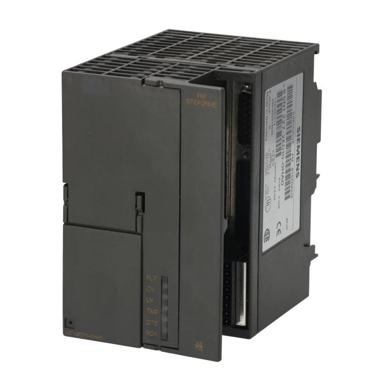
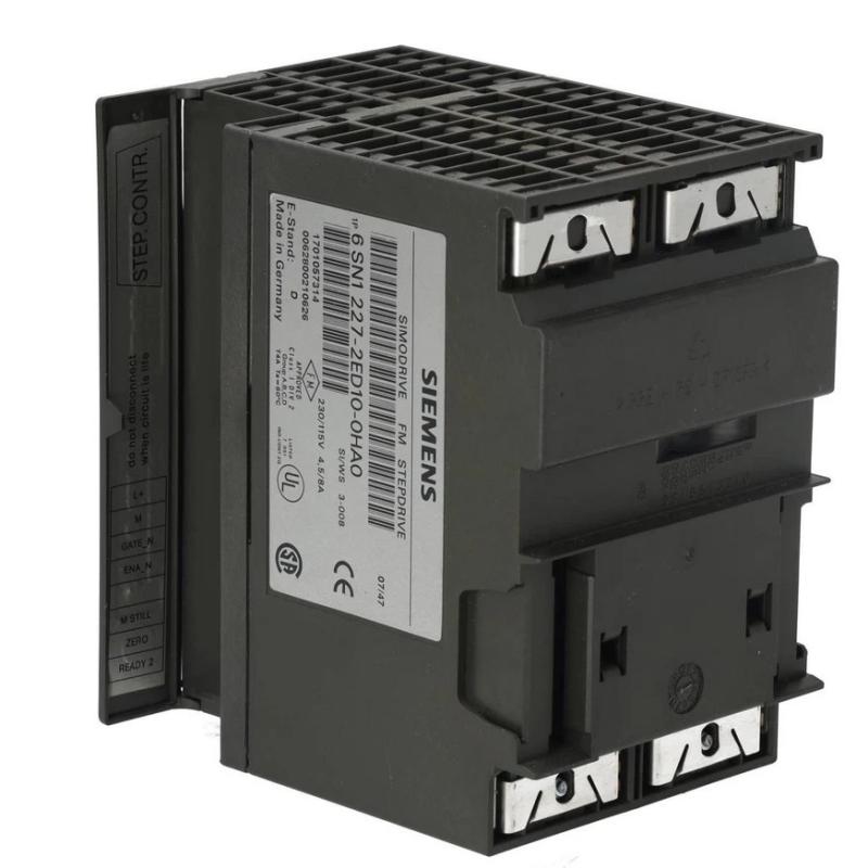
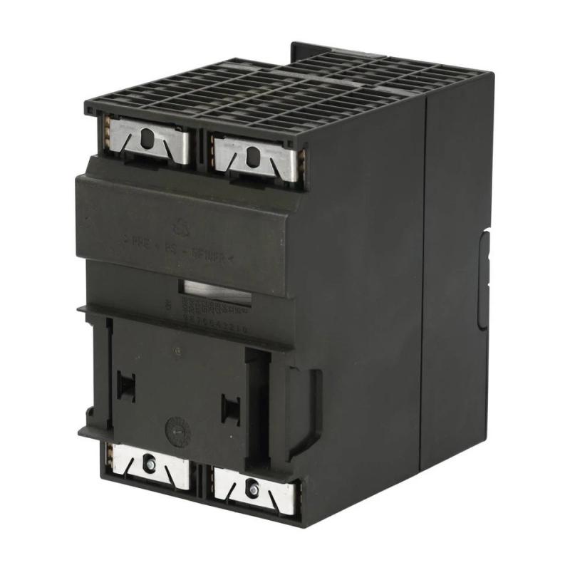
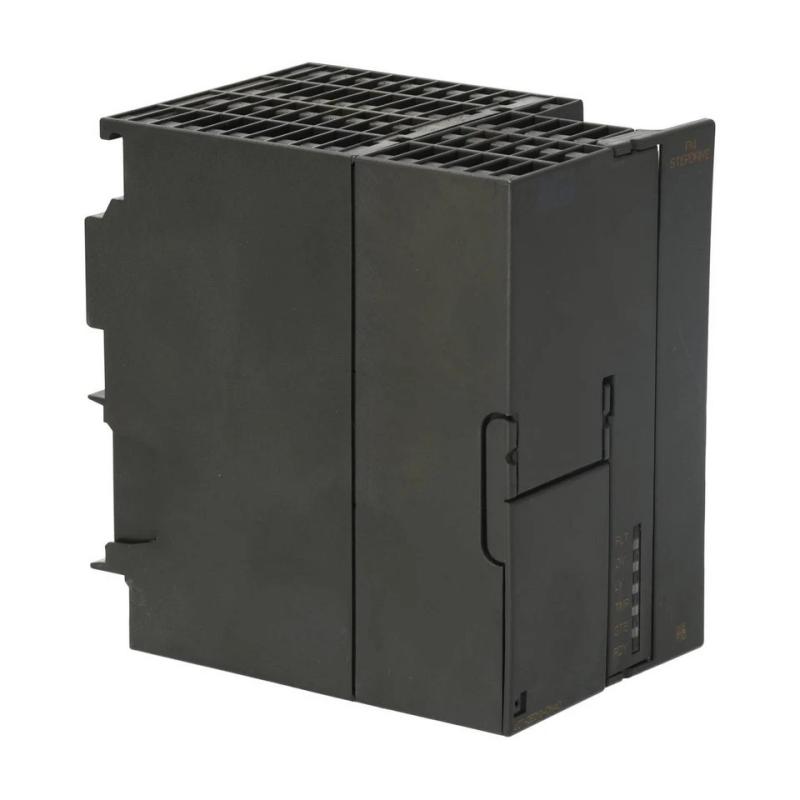
- Siemens
- 6SN1227-2ED10-0HA0
- Stepper Driver
- Germany
- 127 × 102 × 127 mm
- 0.9 kg
- Xiamen, China
- New & In Stock
- T/T, PayPal, Western Union
- 1 Year
- 1-3 Working Days
- DHL, UPS, TNT, FedEx and EMS.
- 24-Hour Service
- COO
- 7
Our advantage

Global Logistics
We have a 10-year logistics and express cooperation agreement, so our products can be shipped to any place in the world.

Brand new and original
Our products are imported in bulk from the place of origin. Because of the cooperative relationship, our products are all original and 100% new.

24-hour service
We provide 7*24 hours service to our customers. We will be there whenever you need us.

Price advantage
All our products are priced very favorably because we have our own warehouse and supply.
| Company Information | |||
| [email protected] | |||
| Mobile | +8615980777398 | ||
| +8615980777398 | |||
| 15980777398 |
Product Overview
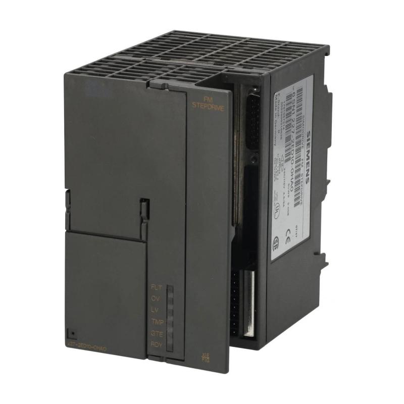
The Siemens 6SN1227-2ED10-0HA0 FM STEPDRIVE is a stepper motor power unit designed for use with compatible Siemens SIMOSTEP stepper motors. It belongs to the Siemens SIMATIC FM STEPDRIVE product family and provides the power electronics required to operate stepper motors in industrial positioning and motion-control applications.
Unlike a conventional variable frequency drive designed primarily for AC motor speed control, the FM STEPDRIVE is intended for stepper motor systems. It receives control signals from a compatible positioning controller and supplies the electrical power required to move the motor according to the commanded stepping sequence.
Stepper motor systems are commonly used where repeatable incremental movement and controlled positioning are required. Applications may include cutting-to-length machinery, material feeding, compact positioning equipment, and selected automated production processes.
The 6SN1227-2ED10-0HA0 supports selectable 115 V AC or 230 V AC input, with a specified input tolerance of ±20%. Its motor phase current is adjustable from 1.7 A to 6.8 A. The unit also supports 24 V DC signal interfaces and a 5 V pulse interface through a 15-pin D-sub connector.
The power unit is designed for integration with compatible motion-control equipment rather than operation as a standalone controller. A positioning module or controller supplies the required command signals, while the FM STEPDRIVE manages the motor power stage.
The model is now discontinued, so it is particularly relevant to maintenance teams responsible for existing Siemens stepper motor installations. When sourcing a replacement, engineers should verify the full order number, input voltage selection, motor compatibility, signal interface, and mounting requirements.
Technical Specifications
| Parameter | Specification |
|---|---|
| Brand | Siemens |
| Product Family | SIMATIC FM STEPDRIVE |
| Model Number | 6SN1227-2ED10-0HA0 |
| Product Type | Stepper Motor Power Unit / Stepper Drive |
| Intended Motor Family | Compatible SIMOSTEP stepper motors |
| AC Supply Voltage | 115/230 V AC, selectable |
| Input Voltage Tolerance | ±20% |
| Maximum Input Current | 11 A at 115 V / 5.5 A at 230 V |
| Supply Frequency | 47–63 Hz |
| Signal Supply Voltage | 24 V DC |
| Signal Voltage Range | 20.4–28.8 V DC |
| Maximum Signal Supply Current | 1.5 A |
| Adjustable Motor Phase Current | 1.7–6.8 A |
| Pulse Interface | 5 V signals |
| Signal Interface | 24 V I/O |
| Connector | 15-pin D-sub socket |
| Degree of Protection | IP20 |
| Operating Temperature | 0–60°C, subject to derating and mounting conditions |
| Condensation | Not permissible |
| Dimensions Provided | 127 × 102 × 127 mm |
| Manufacturer Reference Dimensions | Approximately 80 × 125 × 118 mm (W × H × D) |
| Weight | Approximately 0.9 kg |
| Product Lifecycle | Discontinued |
Important: The dimensions supplied for the product listing differ from the dimensions in the manufacturer’s technical data. Verify the actual unit and its mechanical drawing before designing a mounting arrangement or preparing shipping documentation.
Function and Working Principle
The FM STEPDRIVE functions as the power stage in a stepper motor control system. It receives command signals from an appropriate controller and uses its power electronics to energize the motor windings in a controlled sequence.
1. Stepper Motor Power Control
A stepper motor moves in discrete angular increments when its windings are energized in the correct sequence. The controller determines the required movement, while the drive provides the electrical current needed by the motor.
The 6SN1227-2ED10-0HA0 supplies controlled motor power for compatible SIMOSTEP motors. Its current adjustment range allows the drive to be configured for suitable motor requirements within the supported operating limits.
Correct current settings are important because excessive current can cause overheating, while insufficient current may result in reduced torque or unreliable movement.
2. Pulse-Based Motion Commands
The drive supports a 5 V pulse interface. In a compatible motion-control system, pulse signals can represent commanded movement, while additional signals may control enabling and other operating functions.
The relationship between command pulses and motor movement depends on the motor’s step angle, drive settings, and the controller’s configuration. The drive should therefore be configured as part of the complete motion system rather than treated as an independent positioning controller.
3. Adjustable Motor Phase Current
The unit provides an adjustable phase-current range of 1.7–6.8 A. This setting must be selected according to the connected motor’s rated current and the applicable Siemens configuration instructions.
Correct adjustment helps balance motor torque, electrical loading, and thermal performance. Engineers should not assume that the maximum current setting is appropriate for every compatible motor.
4. Positioning System Coordination
The FM STEPDRIVE operates in conjunction with a positioning controller or motion-control module. The controller determines the movement sequence and issues the required commands; the power unit supplies the electrical drive capability.
The resulting system can perform controlled incremental movement for applications such as feeding material by a defined distance or moving a component between predetermined positions.
Actual positioning accuracy depends on the motor, mechanical transmission, load, controller configuration, and any feedback or homing arrangements used by the application.
Role in Industrial Automation Systems
The 6SN1227-2ED10-0HA0 is a power component within a larger automation architecture. It does not replace the PLC or positioning controller responsible for calculating and coordinating motion commands.
PLC and Positioning Module Integration
A compatible PLC and positioning module can generate the command signals required by the stepper drive. The controller executes the machine sequence, while the FM STEPDRIVE powers the motor.
Siemens application documentation describes the FM STEPDRIVE in a stepper motor positioning arrangement using SIMATIC S7-200 equipment and an EM 253 positioning module. This illustrates the type of coordinated control architecture for which the unit was intended.
When maintaining an existing installation, confirm the original controller, module, signal assignments, connector wiring, and software configuration before replacing the drive.
Signal Interface
The drive provides a 5 V pulse interface and a 24 V signal interface. These interfaces serve different electrical purposes and must be connected according to the manufacturer’s documentation.
Incorrect voltage levels or signal wiring can prevent the drive from responding properly and may damage connected equipment. Do not assume that all PLC output types can connect directly to the drive without checking the interface requirements.
Motor and Mechanical System Integration
The motor is typically connected to the drive through an appropriate motor power cable. The mechanical load may include a lead screw, belt, feed mechanism, indexing table, or another positioning assembly.
The selected motor must provide sufficient torque for the load and acceleration profile. The mechanical system must also be designed to manage backlash, friction, inertia, and travel limits.
Operator Interface and Machine Monitoring
An HMI may allow operators to enter movement distances, select operating modes, or monitor machine status through the PLC. The exact arrangement depends on the controller and the original machine design.
The FM STEPDRIVE should be treated as the motor power unit, with operating sequences and higher-level coordination handled by the relevant control equipment.
Industrial Applications
The Siemens 6SN1227-2ED10-0HA0 is intended for compatible stepper motor positioning systems. Its practical suitability depends on motor ratings, load torque, positioning requirements, and the available controller interface.
1. Cutting-to-Length Machines
Cutting-to-length systems feed material by a defined distance before a cutting operation. A stepper motor can control a feed mechanism, while the controller coordinates material movement and the cutting sequence.
The FM STEPDRIVE can serve as the motor power stage when the motor and positioning hardware are compatible with the original design.
2. Material Feeding Equipment
Automated production lines often require material to advance in controlled increments. Examples include feeding strips, sheets, packaging material, or small components into a processing station.
The stepper drive supplies the motor power needed for commanded movement. Feed accuracy depends on the complete mechanical and control system, including roller diameter, transmission ratio, motor characteristics, and calibration.
3. Compact Positioning Mechanisms
Stepper motor systems are frequently used for incremental positioning in fixtures, guides, adjustment mechanisms, and compact automation equipment.
The FM STEPDRIVE can be used in a compatible configuration where the required torque, speed, and electrical ratings remain within the system’s limits.
4. Packaging Machinery
Packaging equipment may use stepper motors to advance film, position labels, or move material between process stages. Controlled incremental movement can help coordinate mechanical operations with the production sequence.
Engineers must consider cycle rate, acceleration, motor heating, and the risk of lost steps under changing loads.
5. Legacy Siemens Automation Systems
The 6SN1227-2ED10-0HA0 may be encountered in older Siemens-based motion-control installations. In these systems, preserving the original drive can help avoid extensive changes to controller wiring and machine software.
Because the product is discontinued, accurate identification and careful condition assessment are particularly important when sourcing a spare unit.
Installation and System Integration
Correct installation is essential for electrical safety, reliable motor movement, and long-term operation.
1. Confirm the Input Voltage
The drive supports selectable 115 V AC and 230 V AC input, with a specified tolerance of ±20%. Confirm the intended voltage selection and the actual supply before energizing the unit.
The maximum input current differs by supply voltage: 11 A at 115 V and 5.5 A at 230 V. Protective devices and wiring must be selected in accordance with the manufacturer’s requirements and local electrical codes.
2. Verify Mounting Dimensions
The supplied product listing dimensions are 127 × 102 × 127 mm, while the technical data gives approximately 80 × 125 × 118 mm for width, height, and depth.
These values should be reconciled before creating a mounting plate or replacing an installed unit. Confirm the exact housing, mounting points, connector clearance, and required ventilation space.
The drive has an IP20 protection rating and must be installed in a suitable cabinet. It should not be exposed directly to water, condensation, or conductive contamination.
3. Connect the Correct Control Interface
Check whether the application uses the 5 V pulse interface or the 24 V signal interface for the relevant commands. Verify the signal polarity, enabling requirements, connector pin assignments, and grounding arrangements.
Never connect a controller output to the drive based solely on connector appearance. Electrical compatibility must be confirmed from the original documentation.
4. Set the Motor Current
Adjust the motor phase current according to the connected SIMOSTEP motor’s requirements and the drive’s instructions. Check the motor wiring and phase connections before applying power.
An incorrect current setting can lead to excessive motor heating, reduced torque, or unreliable movement.
5. Select Appropriate Motor and Cable Components
Use a motor that is compatible with the FM STEPDRIVE and satisfies the application’s torque and speed requirements. Select motor and signal cables according to the required electrical ratings, cable length, shielding, and installation environment.
Cable routing should minimize interference between motor power conductors and sensitive control signals.
6. Test Motion Before Production
After installation, test the drive at a safe operating condition. Verify enabling signals, direction of movement, pulse response, current settings, and the behavior of any limit switches or homing routines.
Check for abnormal noise, overheating, vibration, and missed steps. Record the final settings and wiring information for future maintenance.
Compatible System Components
The FM STEPDRIVE is intended to be used with a compatible controller, stepper motor, and associated wiring. The following are examples of components or system elements that may be required, depending on the installation.
| Component | Function | Integration Considerations |
|---|---|---|
| SIMOSTEP stepper motor | Converts electrical commands into incremental movement | Verify motor compatibility, phase current, torque, and speed |
| Siemens SIMATIC S7-200 PLC | Executes machine-control logic in applicable legacy systems | Confirm the original CPU and available outputs |
| Siemens EM 253 positioning module | Generates positioning commands in documented S7-200 applications | Verify hardware compatibility and original configuration |
| 5 V pulse interface | Carries compatible motion command signals | Check pulse characteristics and connector wiring |
| 24 V DC signal supply | Supports compatible control signals | Confirm voltage, current capacity, and signal assignments |
| Motor power cable | Connects the drive to the motor | Verify conductor size, length, and insulation ratings |
| 15-pin D-sub connector | Provides the drive’s pulse interface connection | Confirm connector type and pinout |
| Mounting rail or panel | Supports physical installation | Check dimensions, mounting points, and ventilation |
| Protective electrical devices | Provide supply-side protection and isolation | Follow the manufacturer’s instructions and applicable codes |
The components listed above are not necessarily supplied with the drive. Verify the original machine bill of materials before purchasing accessories or replacement parts.
Alternative Models and Replacement Considerations
The 6SN1227-2ED10-0HA0 is discontinued. Selecting a replacement requires more than matching the physical dimensions or nominal current rating.
| Replacement Approach | Considerations |
|---|---|
| Same model, verified condition | Often the most straightforward option for preserving an existing system, provided the unit is genuine and tested |
| Compatible FM STEPDRIVE variant | Requires verification of supply voltage, motor compatibility, signal interfaces, and current range |
| Alternative Siemens stepper drive | May require changes to wiring, control signals, parameter settings, or mounting |
| Modern stepper drive system | May require a new controller interface, revised PLC logic, and system recommissioning |
| Servo-based positioning system | Could provide different motion capabilities but typically involves more extensive engineering changes |
Before choosing a replacement, verify:
- Input voltage and current requirements.
- Motor type and rated phase current.
- Pulse and signal interface compatibility.
- Connector pin assignments.
- Required torque, speed, and positioning performance.
- Controller and positioning-module compatibility.
- Mechanical dimensions and mounting points.
- Environmental conditions and cabinet requirements.
- Availability of configuration software and technical documentation.
A replacement should be validated as part of the complete machine-control system. Similar product names or matching current ratings do not guarantee electrical or functional compatibility.
Key Advantages
Dedicated Stepper Motor Power Stage
The FM STEPDRIVE is designed for compatible stepper motor systems and provides the power stage required for controlled incremental movement.
Selectable AC Supply
Its selectable 115 V AC and 230 V AC input supports different supply arrangements within the specified operating limits.
Adjustable Phase Current
The 1.7–6.8 A phase-current range allows configuration for compatible motor requirements.
Multiple Signal Interfaces
The 5 V pulse interface and 24 V signal interface support integration with suitable positioning controllers and control circuits.
Compact Industrial Construction
The unit has a manufacturer-listed weight of approximately 0.9 kg, making it a relatively compact component for cabinet-mounted motion-control installations.
Use in Established Siemens Systems
The drive is documented for use with SIMOSTEP motors and compatible Siemens positioning equipment, which is important when maintaining legacy automation machinery.
Technical FAQs
1. What is the Siemens 6SN1227-2ED10-0HA0?
It is a Siemens SIMATIC FM STEPDRIVE power unit designed to drive compatible SIMOSTEP stepper motors in industrial positioning applications.
2. Is it a conventional AC servo drive?
No. It is a stepper motor power unit. Its role is to supply controlled electrical power to a compatible stepper motor based on commands from a positioning controller.
3. What input voltage does the unit support?
The specified input is selectable 115 V AC or 230 V AC, with a tolerance of ±20%. Confirm the selected voltage and supply conditions before installation.
4. What is the adjustable motor current range?
The specified motor phase-current range is 1.7–6.8 A. The setting must match the connected motor and the manufacturer’s instructions.
5. Which control interfaces are available?
The unit supports a 5 V pulse interface and a 24 V signal interface. Confirm the required signal type, pinout, and controller compatibility before wiring.
6. What is the weight of the 6SN1227-2ED10-0HA0?
The manufacturer’s product listing gives a net weight of approximately 0.9 kg.
7. Why do the supplied dimensions differ from the manufacturer’s dimensions?
The supplied listing values may use a different measurement convention or may correspond to another packaging or product configuration. The manufacturer reference dimensions are approximately 80 × 125 × 118 mm. Confirm the physical unit before finalizing mounting or shipping details.
8. Is the product still manufactured by Siemens?
No. Siemens lists the product as discontinued. Availability may depend on remaining inventory, specialist spare-parts suppliers, or repair and exchange services.
9. Can another stepper drive replace this model?
Potentially, but the replacement must support the motor’s electrical requirements, the controller’s signal interface, and the application’s motion characteristics. Wiring and control-program changes may be necessary.
10. What should buyers check when sourcing a used unit?
Verify the complete order number, nameplate, physical condition, terminals, connector condition, and available test results. Confirm whether accessories are included and whether the supplier provides a warranty or return policy.
Procurement and Maintenance Recommendations
Because the Siemens 6SN1227-2ED10-0HA0 is discontinued, procurement should begin with exact model verification. Check the complete order number on the installed unit and compare the electrical and interface specifications with the replacement being offered.
For used or refurbished products, request clear photographs of the nameplate, housing, terminals, and connectors. Ask whether the unit has been functionally tested and confirm the warranty and return conditions before ordering.
During maintenance, inspect wiring, connector contacts, grounding, mounting, and cabinet ventilation. Keep the equipment free from dust and condensation. Check the motor-current setting and control signals if the system experiences reduced torque, inconsistent movement, or missed steps.
Before replacing the drive, document the existing wiring, controller configuration, motor type, and operating parameters. Where a modern alternative is considered, evaluate the complete motion-control system rather than assuming that a different drive can be installed without further engineering.
Conclusion
The Siemens 6SN1227-2ED10-0HA0 SIMATIC FM STEPDRIVE is a dedicated power unit for compatible SIMOSTEP stepper motors. It supports selectable 115/230 V AC input, adjustable motor phase current from 1.7 A to 6.8 A, a 5 V pulse interface, and 24 V signal I/O.
For legacy positioning systems, the key purchasing and maintenance priorities are accurate model identification, correct motor-current configuration, compatible control signals, and verified mechanical dimensions. Since the model is discontinued, any replacement should be checked carefully against the original system requirements before installation.