

ProductPRODUCT
Featured products
Contact Us
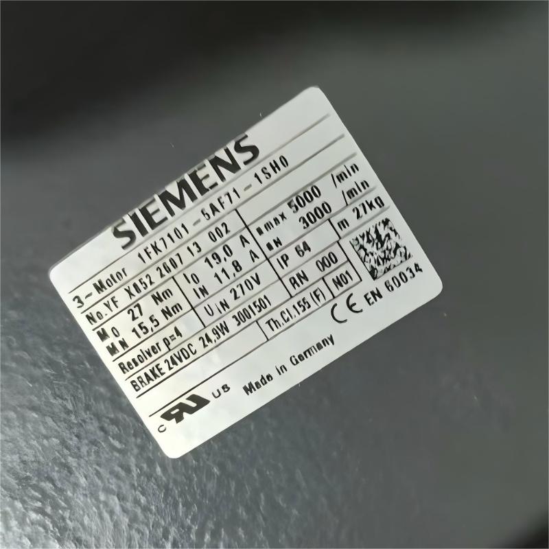
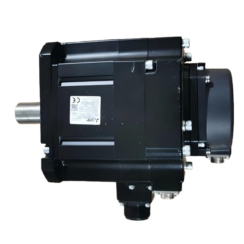
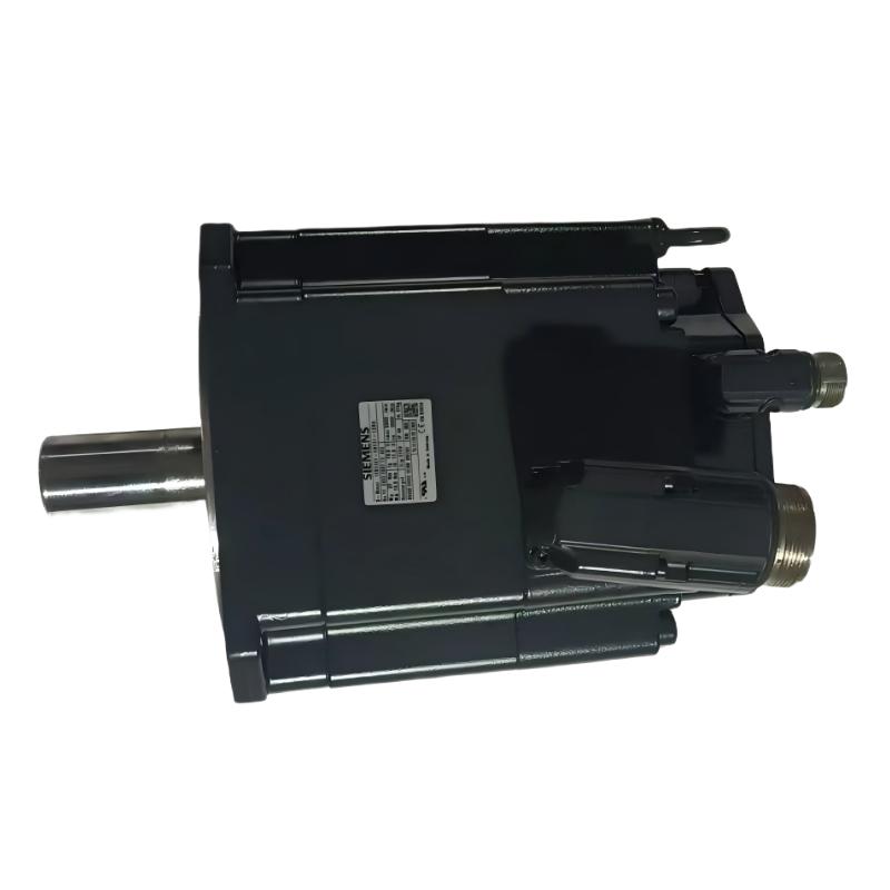
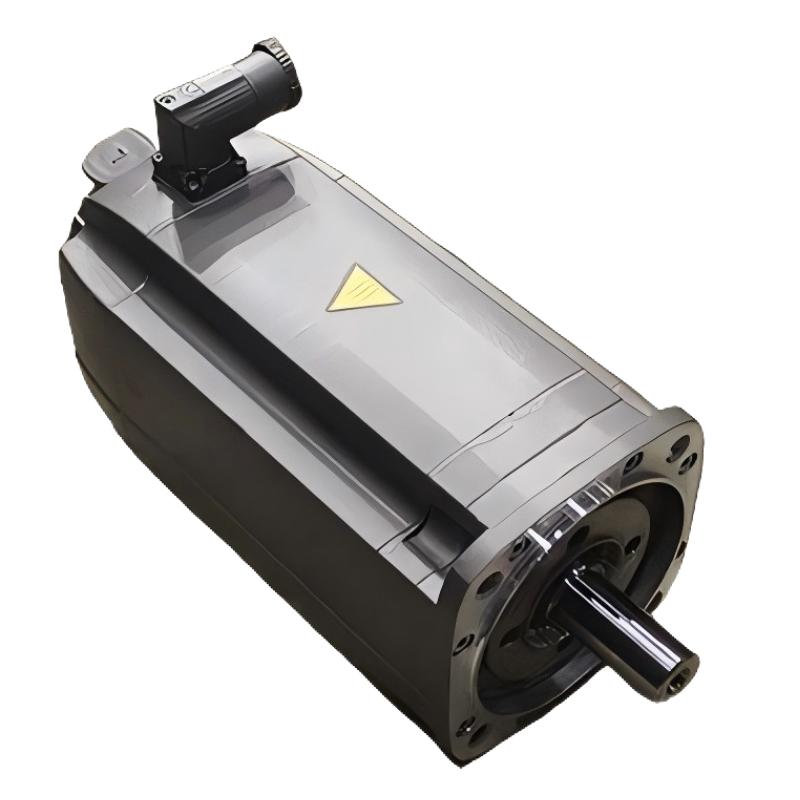
- Siemens
- 1FK7101-5AF71-1SH0
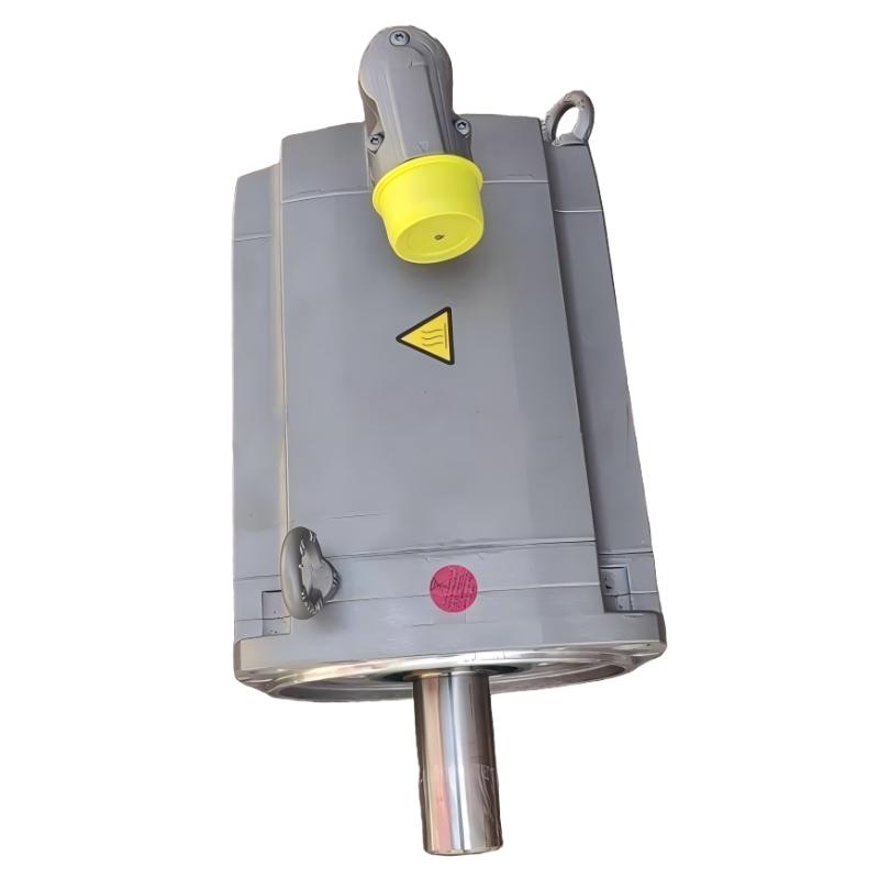
- SIMOTICS S Synchronous Motor
- Germany
- 300 mm x 200 mm x 150 mm
- 24kg
- Xiamen, China
- New & In Stock
- T/T, PayPal, Western Union
- 1 Year
- 1-3 Working Days
- DHL, UPS, TNT, FedEx and EMS.
- 24-Hour Service
- COO
- 5
Our advantage

Global Logistics
We have a 10-year logistics and express cooperation agreement, so our products can be shipped to any place in the world.

Brand new and original
Our products are imported in bulk from the place of origin. Because of the cooperative relationship, our products are all original and 100% new.

24-hour service
We provide 7*24 hours service to our customers. We will be there whenever you need us.

Price advantage
All our products are priced very favorably because we have our own warehouse and supply.
| Company Information | |||
| [email protected] | |||
| Mobile | +8615980777398 | ||
| +8615980777398 | |||
| 15980777398 |
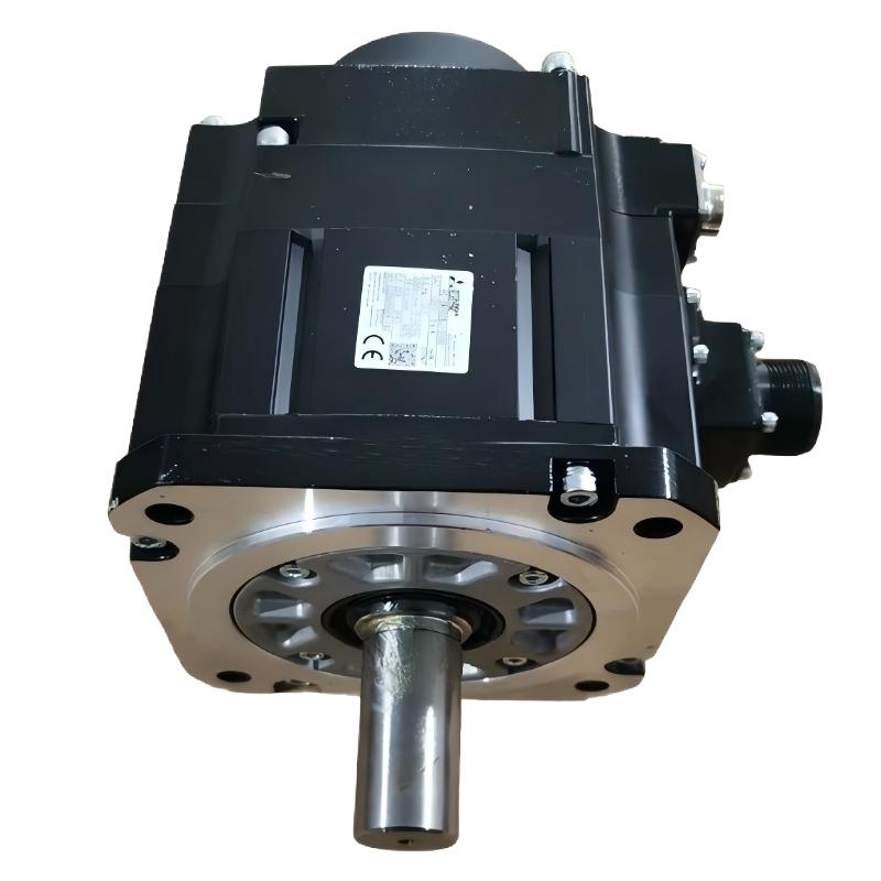
Siemens 1FK7101-5AF71-1SH0 Servo Motor: Technical Specifications, Product Overview, Applications, Advantages, and Related Models
1. Product Overview
The Siemens 1FK7101-5AF71-1SH0 is a model designation associated with the 1FK7 family of industrial servo motors. Motors in this family are designed for industrial motion-control applications that require controlled rotation, repeatable positioning, regulated speed, and integration with automated machinery.
Servo motors are widely used in CNC machine tools, packaging equipment, automated assembly systems, material-handling machinery, and production lines. In these applications, the motor works with a compatible servo drive and control system to deliver the movement required by the machine.
The complete model number is important because motors within the same product family can differ in electrical characteristics, feedback systems, mechanical interfaces, connector arrangements, and other configuration details.
For this reason, the 1FK7101-5AF71-1SH0 should be identified by its full model designation when evaluating a replacement, preparing a purchase order, or checking compatibility with existing equipment.
This guide covers the product’s identification, technical parameters, construction, operating principles, industrial applications, advantages, installation requirements, maintenance considerations, and related motor candidates.
Technical accuracy note: The exact rated power, rated torque, rated speed, overall dimensions, shaft dimensions, and net weight of the complete 1FK7101-5AF71-1SH0 configuration cannot be established reliably from the model designation alone. Where exact specifications are not confirmed, they are marked accordingly rather than presented as guaranteed values. Family-level figures, where included for preliminary comparison, should be checked against the actual motor nameplate before use.
4. Detailed Technical Specifications
The following table summarizes the principal electrical and mechanical characteristics associated with the 1FK7101-5AF71-1SH0 configuration.
| Parameter | Technical Specification |
|---|---|
| Model | 1FK7101-5AF71-1SH0 |
| Brand | Siemens |
| Product Family | SIMOTICS |
| Product Series | SIMOTICS S-1FK7 Compact |
| Motor Type | Three-phase synchronous servo motor |
| Motor Technology | Permanent-magnet synchronous motor |
| Cooling Method | Natural cooling |
| Rated Power | Approximately 4.85 kW |
| Rated Torque | 15.5 Nm at the specified 100 K temperature-rise rating |
| Static Torque | 27 Nm at the specified 100 K temperature-rise rating |
| Static Torque at 60 K | Approximately 22.4 Nm |
| Rated Speed | 3,000 rpm |
| Maximum Permissible Mechanical Speed | 5,000 rpm for the corresponding motor configuration; confirm the exact operating limits |
| Maximum Torque | Up to approximately 80 Nm under specified limiting conditions |
| Rated Current | Approximately 11.8 A |
| Maximum Current | Approximately 63 A under the specified limiting conditions |
| Number of Poles | 8 |
| Number of Pole Pairs | 4 |
| Feedback System | Multipole resolver |
| DRIVE-CLiQ Interface | Not included in the identified resolver configuration |
| Shaft Design | Plain shaft |
| Shaft Tolerance | N |
| Holding Brake | Included |
| Brake Type | Permanent-magnet holding brake |
| Mounting Arrangement | IM B5; IM V1 and IM V3 arrangements may be supported where permitted by the exact configuration |
| Shaft Height | 100 mm |
| Protection Rating | IP64 for the identified configuration |
| Power Connection | Power connector |
| Signal Connection | Separate signal connection arrangement |
| Connector Orientation | Rotatable connector arrangement; confirm the available adjustment range in the installation documentation |
| Rated Voltage | Depends on the drive and DC-link configuration; verify the exact motor documentation |
| Rotor Moment of Inertia | Approximately 79.9 × 10⁻⁴ kg·m² without brake for the corresponding motor configuration |
| Rotor Inertia with Brake | Higher than the motor-only value; confirm the exact configuration |
| Overall Dimensions | Refer to the dimensional table below |
| Mounting Dimensions | Refer to the dimensional table below |
| Net Weight (kg) | Approximately 24 kg for the corresponding motor configuration with holding brake |
| Typical Application | Industrial automation and controlled-motion machinery |
The motor’s rated power and torque are consistent with a servo motor intended for industrial motion-control applications.
The holding brake is an important distinguishing feature of the 1SH0 configuration. It can help hold a stationary axis when the system is correctly designed for that purpose.
A holding brake should not be assumed to provide the same function as a continuously operating service brake. Its suitability for emergency stopping, dynamic braking, or other safety functions must be established from the applicable brake specifications and machine safety design.
4.1 Rated Power and Torque
Rated power and rated torque describe different aspects of motor performance.
Rated power represents the motor’s specified mechanical output under the applicable operating conditions. Rated torque indicates the torque available under the stated rating conditions.
For a rotating motor, the relationship between power, torque, and speed is:
\[ P=\frac{T\times n}{9550} \]
Where:
- \(P\) = mechanical power in kW.
- \(T\) = torque in Nm.
- \(n\) = rotational speed in rpm.
Using 15.5 Nm and 3,000 rpm:
\[ P=\frac{15.5\times3000}{9550}\approx4.87\text{ kW} \]
This is consistent with the approximately 4.85 kW rating associated with this motor configuration.
The calculation is useful for checking the relationship between the rated figures. It does not mean that the motor can deliver its rated torque at every speed or under every duty cycle.
4.2 Rated Torque and Static Torque
The motor’s rated torque is approximately 15.5 Nm under the stated 100 K temperature-rise rating.
Its static torque is approximately 27 Nm under the corresponding 100 K condition.
These values should not be confused.
Rated torque is relevant to the motor’s specified operating performance. Static torque refers to a standstill condition and is not automatically available as continuous torque during rotation.
The actual operating torque depends on the motor’s thermal limits, drive current, speed, duty cycle, ambient temperature, and cooling conditions.
4.3 Rated Speed and Maximum Speed
The rated speed is approximately 3,000 rpm.
A maximum permissible mechanical speed of 5,000 rpm is associated with the corresponding motor configuration, but the permitted speed in an installed system can be lower.
The drive’s voltage, current, control settings, load characteristics, and mechanical limitations all affect the available operating range.
For this reason, 5,000 rpm should be treated as a reference limit rather than a recommended continuous operating speed.
5. Dimensions and Weight
Dimensions and weight are essential when replacing a motor or designing the mounting structure of a new machine.
The 1FK7101-5AF71-1SH0 is associated with a 100 mm shaft-height category. The exact installation envelope must be checked against the dimensional drawing for the motor with its holding brake.
5.1 Mechanical Dimensions
| Parameter | Dimension | Unit | Notes |
|---|---|---|---|
| Model | 1FK7101-5AF71-1SH0 | — | Complete ordering designation |
| Shaft Height | 100 | mm | Reference shaft-height category |
| Mounting Flange Width | 180 | mm | Corresponding frame drawing dimension; verify drawing convention |
| Mounting Flange Height | 240 | mm | Corresponding frame drawing dimension; verify drawing convention |
| Mounting Flange Bolt-Circle Dimension | 215 | mm | Confirm the exact mounting pattern before installation |
| Mounting Face Reference Dimension | 192 | mm | Drawing-dependent dimension |
| Mounting-Hole or Clearance Feature | 13 | mm | Confirm whether this is the applicable feature for the selected mounting interface |
| Housing Reference Dimension | 160 | mm | Drawing-dependent |
| Housing Reference Dimension | 96 | mm | Drawing-dependent |
| Shaft Reference Dimension | 80 | mm | Confirm the specific dimension represented in the drawing |
| Shaft Diameter | Requires dimensional drawing | mm | Must match the coupling |
| Shaft Extension Length | Requires dimensional drawing | mm | Important for coupling engagement |
| Overall Axial Length | Approximately 240 | mm | Preliminary reference for the corresponding motor with brake; verify the dimension convention |
| Connector Clearance | Requires dimensional drawing | mm | Depends on connector orientation and cable routing |
| Net Weight (kg) | Approximately 24 | kg | Reference value for the corresponding motor with brake |
| Shipping Weight (kg) | Not confirmed | kg | Includes packaging and potentially additional supplied components |
Important dimensional qualification: The values above are preliminary references drawn from the corresponding 1FK7101 mechanical size and configuration. They are not a substitute for the exact dimensional drawing of the 1FK7101-5AF71-1SH0. In particular, the flange, shaft, and overall-length dimensions must be interpreted according to the drawing’s dimension labels.
For a replacement installation, compare the original motor’s mounting holes, shaft extension, shaft diameter, coupling position, and connector clearance before approving the new unit.
5.2 Weight Considerations
The approximate net weight for the corresponding motor configuration with a holding brake is 24 kg.
The actual supplied weight may differ depending on the exact configuration and the components included.
For lifting and mounting calculations, use the confirmed product weight. For shipping and logistics, use the packaged weight supplied with the shipment information.
The holding brake also increases rotor inertia. If the motor is used on a moving axis, the additional inertia should be included in the motion-system calculations.
6. Product Description and Operating Principle
6.1 General Description
The 1FK7101-5AF71-1SH0 is a three-phase synchronous servo motor intended for controlled movement in industrial machinery.
Its permanent-magnet rotor interacts with the electromagnetic field generated by the stator windings to produce rotational torque.
The motor is normally used with a compatible servo drive and motion controller. The controller determines the requested movement, while the drive regulates the motor’s electrical operation.
In a feedback-controlled system, information from the resolver helps the drive determine rotor position and support the required motion-control functions.
The complete system can be configured to control position, speed, and torque, subject to the capabilities of the selected drive and controller.
6.2 Multipole Resolver Feedback
The identified 1SH0 configuration uses a multipole resolver rather than the DRIVE-CLiQ feedback arrangement associated with some other motor variants.
A resolver is an electromechanical position-feedback device that provides signals from which the connected drive can determine rotor position.
The drive must support the correct resolver type and electrical interface.
The resolver’s characteristics influence the feedback configuration, commissioning procedure, and compatible drive selection.
A motor with a resolver should not automatically be treated as interchangeable with a motor fitted with an incremental encoder or a different absolute encoder.
Even if two motors have similar rated power, torque, and dimensions, different feedback arrangements can prevent direct replacement without corresponding changes to the drive or control system.
6.3 Plain Shaft Design
The motor uses a plain-shaft configuration.
The shaft transfers rotational torque to the connected mechanical equipment through a compatible coupling or transmission.
The absence of a shaft key in a particular configuration can affect coupling selection and torque transmission.
The coupling must be designed for the actual shaft geometry, load, speed, and required torque.
Before installation, confirm the shaft diameter, shaft extension, tolerances, and permitted radial and axial loading.
6.4 Holding Brake
The 1SH0 configuration is identified with a permanent-magnet holding brake.
A holding brake is commonly used to maintain the position of a stationary axis when the drive is not actively producing the torque needed to support the load.
This can be useful in vertical axes, lifting mechanisms, and other applications where uncontrolled movement after power loss would create a problem.
The brake must be sized and controlled according to the application.
A holding brake should not be used for frequent dynamic stopping unless the specified brake characteristics explicitly permit that operating mode.
6.5 Natural Cooling
The motor uses natural cooling.
This means the motor relies on its designed heat-dissipation characteristics rather than requiring a dedicated forced-air cooling system as its primary cooling method.
The surrounding installation must still provide sufficient space for heat dissipation.
High ambient temperature, restricted airflow, excessive loading, and frequent acceleration cycles can increase thermal stress.
The motor should be operated within its specified current, torque, speed, and thermal limits.
7. Product Applications
The 1FK7101-5AF71-1SH0 is suitable for consideration in industrial systems requiring controlled rotation and repeatable motion.
Its combination of approximately 4.85 kW rated power, 3,000 rpm rated speed, and an integrated holding brake makes the exact configuration particularly relevant when evaluating applications that require both controlled movement and stationary holding.
Final suitability depends on the machine’s torque requirements, operating cycle, feedback interface, brake requirements, and mechanical installation.
7.1 CNC Machine Tools
CNC machine tools use servo systems to control the position and movement of tools, workpieces, and mechanical axes.
Servo motors may be used for feed mechanisms, positioning units, and other controlled movements.
Typical requirements include:
- Repeatable positioning.
- Controlled acceleration and deceleration.
- Stable speed regulation.
- Coordination between multiple axes.
- Consistent movement during repeated production cycles.
When evaluating this motor for CNC machinery, calculate the required torque at the motor shaft and consider the reflected inertia of the mechanical transmission.
The motor’s rated speed should also be compared with the machine’s required feed rate and transmission ratio.
7.2 Packaging Machinery
Packaging equipment commonly uses servo motors to control product feeding, cutting, sealing, labeling, and transfer mechanisms.
A servo system can execute programmed movement profiles and coordinate different machine operations.
Potential applications include film-feeding units, indexing mechanisms, cutting systems, and automated transfer equipment.
The integrated holding brake may be useful where stationary holding is required, but its actual role must be determined by the machine design.
7.3 Automated Assembly Equipment
Assembly machines often need to position components accurately before fastening, insertion, or joining operations.
Servo motors can drive positioning tables, transfer mechanisms, and other automated axes.
A correctly selected servo system can help maintain repeatable movement between assembly cycles.
For pressing or insertion applications, the system may also require force sensors, torque monitoring, or specialized control functions.
Motor torque alone does not establish the maximum force that can safely be applied to a component.
7.4 Material Handling and Vertical Axes
Material-handling systems use servo motors to position loads and coordinate transfer operations.
Potential applications include automated positioning units, lifting mechanisms, transfer tables, and other motion-controlled equipment.
The holding brake may be relevant for a vertical axis or another mechanism that must remain stationary under load.
However, brake suitability must be assessed using the brake’s holding torque, operating limits, mechanical transmission, and the consequences of power loss.
The brake should not be treated as the only safety measure where the application requires additional mechanical restraint or safety-rated equipment.
7.5 Printing and Converting Machinery
Printing and converting equipment may require coordinated motion across feeding, cutting, indexing, and material-transfer mechanisms.
Servo motors can provide controlled movement for these operations.
The required motor characteristics depend on the load inertia, operating speed, production cycle, and transmission arrangement.
7.6 Automated Production Lines
Automated production lines rely on coordinated movement between individual machine stations.
Servo motors can support controlled positioning, product transfer, indexing, and other programmed movements.
The motor should be selected as part of the complete motion-control system, taking account of the drive, controller, feedback interface, and mechanical load.
7.7 Special-Purpose Machinery
Custom machinery may require controlled rotational movement, programmable positioning, and stationary holding.
Examples include automated inspection equipment, indexing stations, custom assembly machines, and specialized manufacturing equipment.
For these applications, the 1FK7101-5AF71-1SH0 should be evaluated against the actual torque, speed, inertia, brake, and installation requirements.
8. Product Advantages
8.1 Controlled Motion
The motor can form part of a servo system that regulates movement according to programmed commands.
This is useful when a machine requires controlled positioning, speed regulation, or coordinated motion.
The actual control performance depends on the feedback system, drive, controller, mechanical transmission, and commissioning settings.
8.2 Repeatable Positioning
Repeatability is important in automated production because the same operation may be performed many times.
A properly configured servo system can repeat programmed movements consistently within the limitations of the overall machine.
Mechanical backlash, structural flexibility, thermal expansion, and feedback characteristics all influence the final positioning performance.
8.3 Integrated Holding Brake
The holding brake is a significant characteristic of this model configuration.
It can help maintain a stationary position when the system is designed to use the brake for holding.
This is particularly relevant to axes that may otherwise move under gravity or an external mechanical load.
The brake’s actual holding capability and control requirements must be confirmed from the applicable specifications.
8.4 Resolver-Based Feedback
The multipole resolver provides rotor-position feedback to a compatible drive.
Resolver feedback can be useful in industrial motion-control systems that are designed around this type of feedback device.
However, compatibility must be established at the drive level. A resolver-equipped motor is not automatically interchangeable with an encoder-equipped motor.
8.5 Controlled Acceleration and Deceleration
A suitable drive can regulate acceleration and deceleration to meet the machine’s operating requirements.
Controlled motion can help reduce unnecessary mechanical shock and improve cycle consistency.
The motion profile must remain within the motor’s permitted current, torque, speed, and thermal limits.
8.6 Natural Cooling
The natural-cooling arrangement can simplify installation when the machine provides sufficient heat dissipation.
It avoids the need to assume that a dedicated external cooling fan is required for the motor’s primary cooling.
However, installation in a confined enclosure or operation at high load can still create thermal problems.
8.7 Flange-Mounted Construction
The flange-mounted design can simplify installation when the motor’s mounting interface matches the machine structure.
The actual flange pattern, shaft dimensions, and overall length must still be checked.
8.8 Industrial Automation Integration
When combined with a compatible drive and controller, the motor can support programmed motion, controlled stopping, and coordinated movement.
The available functions depend on the complete automation system rather than the motor alone.
9. Brand and Product Series
9.1 Brand: Siemens
The product designation is associated with the Siemens brand.
The complete model number should be retained when requesting quotations, ordering spare parts, checking compatibility, or preparing maintenance records.
9.2 Product Family: SIMOTICS
SIMOTICS is the motor product-family designation associated with the product.
The family covers industrial motors designed for different operating requirements and applications.
The SIMOTICS name does not by itself determine the exact technical specifications of an individual motor.
9.3 Product Series: SIMOTICS S-1FK7 Compact
The 1FK7 Compact series comprises synchronous servo motors intended for industrial motion-control applications.
Products in this series can differ in rated performance, feedback devices, shaft configurations, mounting arrangements, brake options, and protection characteristics.
The 1FK7101-5AF71-1SH0 is identified by its complete configuration, including its resolver feedback and holding brake.
9.4 Product Identification Summary
| Parameter | Information |
|---|---|
| Model | 1FK7101-5AF71-1SH0 |
| Brand | Siemens |
| Product Family | SIMOTICS |
| Product Series | SIMOTICS S-1FK7 Compact |
| Motor Type | Three-phase synchronous servo motor |
| Rated Power | Approximately 4.85 kW |
| Rated Torque | 15.5 Nm at the specified 100 K rating |
| Rated Speed | 3,000 rpm |
| Feedback System | Multipole resolver |
| Holding Brake | Included |
| Shaft Design | Plain shaft |
| Cooling | Natural cooling |
| Protection Rating | IP64 for the identified configuration |
| Shaft Height | 100 mm |
| Net Weight (kg) | Approximately 24 kg with brake, subject to confirmation |
| Main Function | Controlled rotational movement and positioning |
10. Five Related Models for Comparison
The first group focuses on models sharing the principal 1FK7101-5AF71 designation.
These models are useful candidates for investigating configuration differences, especially when replacing an existing motor.
Different suffixes can indicate changes to feedback, holding-brake configuration, protection rating, connector arrangement, or other features.
The table provides preliminary comparison data. Confirm each complete ordering code and its technical specifications before treating it as a direct replacement.
| No. | Model | Brand | Series | Rated Power | Rated Torque | Rated Speed | Dimensions (mm) | Net Weight (kg) |
|---|---|---|---|---|---|---|---|---|
| 1 | 1FK7101-5AF71-1SH0 | Siemens | 1FK7 Compact | Approx. 4.85 kW | 15.5 Nm rated; 27 Nm static | 3,000 rpm | Reference frame: 240 × 180 mm; exact complete envelope to be confirmed | Approx. 24 with brake |
| 2 | 1FK7101-5AF71-1HH0 | Siemens | 1FK7 Compact | Approx. 4.85 kW for the corresponding motor configuration | Approx. 15.5 Nm rated; 27 Nm static | 3,000 rpm | Exact drawing required; shaft height 100 mm | Confirm exact configuration |
| 3 | 1FK7101-5AF71-1SA0 | Siemens | 1FK7 Compact | Approx. 4.85 kW for the corresponding motor configuration | Approx. 15.5 Nm rated; 27 Nm static | 3,000 rpm | Exact drawing required; shaft height 100 mm | Confirm exact configuration |
| 4 | 1FK7101-5AF71-1AG0 | Siemens | 1FK7 Compact | Approx. 4.85 kW | Approx. 15.5 Nm rated; 27 Nm static | 3,000 rpm | Exact drawing required; shaft height 100 mm | Approx. 21 without brake |
| 5 | 1FK7101-5AF71-1DG5 | Siemens | 1FK7 Compact | Approx. 4.85 kW | Approx. 15.5 Nm rated; 27 Nm static | 3,000 rpm | Exact drawing required; shaft height 100 mm | Approx. 21 without brake |
Important: The table is a preliminary comparison, not a guarantee that every suffix configuration is available or mechanically interchangeable. The 1HH0 and 1SA0 entries require confirmation of their exact feedback, brake, and protection characteristics. The 1AG0 and 1DG5 configurations may differ from the target motor in feedback arrangement, brake configuration, and protection rating.
10.1 Recommended Comparison Priorities
When selecting a related motor, compare the following characteristics in order.
First: Feedback compatibility. The target motor uses a multipole resolver. A proposed replacement must provide a feedback interface supported by the existing drive or the drive must be changed accordingly.
Second: Holding-brake requirements. The target configuration includes a holding brake. If the machine depends on that brake, a motor without one is not an equivalent replacement unless the system design is modified appropriately.
Third: Mechanical compatibility. Compare shaft diameter, shaft extension, flange dimensions, mounting holes, and overall length.
Fourth: Electrical ratings. Confirm rated current, voltage, winding characteristics, and the required drive configuration.
Fifth: Protection and environment. Check the motor’s protection rating and suitability for the installation conditions.
A model that shares the same principal designation can still be unsuitable if its suffix identifies a different electrical or mechanical configuration.
11. Five Additional Siemens Servo Motor Models
The second group provides five additional model candidates for a broader comparison.
The models cover different designations within the 1FK7 family. Their purpose is to help identify possible alternatives when the original motor is unavailable or when a different motor size is being considered.
The exact complete ordering codes, electrical ratings, dimensions, and weights must be confirmed before purchasing. Similar model numbers do not guarantee that the same configuration is available across different motor sizes.
| No. | Model | Brand | Product Series | Rated Power | Rated Torque | Rated Speed | Dimensions (mm) | Net Weight (kg) |
|---|---|---|---|---|---|---|---|---|
| 1 | 1FK7083-5AF71-1DG5 | Siemens | 1FK7 Compact candidate | To be confirmed | To be confirmed | To be confirmed | To be confirmed | To be confirmed |
| 2 | 1FK7100-5AF71-1DG5 | Siemens | 1FK7 Compact candidate | To be confirmed | To be confirmed | To be confirmed | To be confirmed | To be confirmed |
| 3 | 1FK7101-5AF71-1DG5 | Siemens | 1FK7 Compact | Approx. 4.85 kW for the corresponding configuration | Approx. 15.5 Nm rated | 3,000 rpm | Exact drawing required | Approx. 21 without brake |
| 4 | 1FK7103-5AF71-1DG5 | Siemens | 1FK7 Compact candidate | To be confirmed | To be confirmed | To be confirmed | To be confirmed | To be confirmed |
| 5 | 1FK7105-5AF71-1DG5 | Siemens | 1FK7 Compact candidate | To be confirmed | To be confirmed | To be confirmed | To be confirmed | To be confirmed |
Model verification notice: The complete model strings in this table are preliminary candidates, not individually confirmed order numbers. The same suffix combination may not be available for every motor size. Do not use these entries as purchase-order specifications without confirming the exact product designation.
11.1 How to Choose Between These Models
The appropriate replacement depends on the application’s electrical, mechanical, and control requirements.
| Selection Criterion | What to Check | Why It Matters |
|---|---|---|
| Model | Full ordering designation | Prevents confusion between different configurations |
| Rated Power | Continuous power requirement | Ensures the motor can meet the machine’s operating demand |
| Rated Torque | Continuous torque requirement | Determines whether the motor can drive the load |
| Peak Torque | Acceleration and transient load requirements | Prevents insufficient short-duration torque capability |
| Rated Speed | Required operating speed | Ensures the machine can achieve its target cycle |
| Maximum Speed | Permitted mechanical and drive limits | Prevents operation beyond specified limits |
| Feedback System | Resolver or supported encoder interface | Determines drive compatibility |
| Holding Brake | Required brake function and rating | Important for gravity-loaded or holding applications |
| Mounting Dimensions | Flange, bolt pattern, and installation envelope | Determines mechanical compatibility |
| Shaft Dimensions | Diameter, length, and shaft-end design | Determines coupling compatibility |
| Overall Dimensions | Length, width, and connector clearance | Ensures the motor fits the machine |
| Net Weight (kg) | Actual motor weight | Supports lifting, mounting, and moving-axis calculations |
| Protection Rating | Required protection against environmental exposure | Helps ensure suitability for the installation environment |
| Drive Compatibility | Complete motor-drive combination | Ensures correct operation and commissioning |
If the goal is a direct replacement, retain the original shaft, mounting, feedback, and brake requirements wherever possible.
If the goal is a new machine design, select the motor according to the calculated load, required motion profile, and available installation space.
12. Installation and Commissioning Requirements
Correct installation is essential for achieving reliable operation and maintaining the motor’s expected service life.
12.1 Mechanical Installation
Before mounting the motor, inspect the shaft, flange, coupling, and connected transmission.
The mounting surface should provide adequate mechanical support, and the shaft should be aligned correctly with the driven mechanism.
Poor alignment can cause vibration, excessive bearing loads, abnormal noise, and premature wear.
Check the following items before installation:
- Mounting-hole dimensions and fasteners.
- Flange compatibility.
- Shaft diameter and extension.
- Coupling alignment.
- Permitted radial and axial shaft loads.
- Connector orientation and clearance.
- Cable routing.
- Motor weight and support requirements.
12.2 Electrical Installation
The motor must be connected according to its specified wiring diagram.
Protective grounding, power-cable selection, shielding, and feedback connections should comply with the applicable installation requirements.
The multipole resolver must be connected to a compatible drive interface.
Incorrect wiring or an incompatible feedback configuration can cause drive faults, unreliable movement, or equipment damage.
12.3 Drive Configuration
The servo drive should be configured for the exact motor and feedback system.
Important settings may include motor identification, rated current, current limits, speed limits, feedback parameters, control-loop settings, and brake control.
Do not copy parameters from a similar motor without confirming that they are appropriate for the installed configuration.
12.4 Holding-Brake Commissioning
Because the 1FK7101-5AF71-1SH0 includes a holding brake, its operation should be checked as part of commissioning.
The brake must be controlled according to the specified electrical and mechanical requirements.
The system should not release a load-bearing brake until the drive can provide the required supporting torque, where the application requires that sequence.
For vertical axes or other potentially hazardous loads, additional mechanical or safety measures may be necessary.
12.5 Initial Operating Test
A controlled commissioning procedure should include:
- Confirm the full motor and drive model numbers.
- Inspect the mechanical installation and shaft alignment.
- Verify the power and resolver connections.
- Confirm the drive’s motor and feedback configuration.
- Check current, torque, speed, and travel limits.
- Test the motor under controlled conditions.
- Verify the direction of rotation.
- Confirm that commanded movement corresponds to the expected feedback.
- Check acceleration, deceleration, and stopping behaviour.
- Test the holding-brake function according to the approved procedure.
- Inspect for abnormal noise, vibration, heating, or drive faults.
The motor should only be operated within its specified electrical, mechanical, and thermal limits.
13. Maintenance and Troubleshooting
Routine inspection can help identify problems before they lead to unexpected production interruptions.
The maintenance schedule should reflect the machine’s operating conditions, duty cycle, environment, and applicable technical requirements.
13.1 Recommended Maintenance Checks
| Inspection Item | Recommended Check | Purpose |
|---|---|---|
| Model | Confirm 1FK7101-5AF71-1SH0 against the equipment records | Prevents errors when ordering spare parts |
| Motor Housing | Check for damage, contamination, and abnormal heating | Helps identify environmental or operating problems |
| Mounting Hardware | Inspect for looseness | Maintains mechanical stability |
| Shaft and Coupling | Check alignment and wear | Reduces mechanical loading |
| Bearings | Monitor unusual noise and vibration | Helps identify developing mechanical problems |
| Power Connections | Inspect according to the maintenance procedure | Supports electrical reliability |
| Resolver Connections | Check cable condition and connection security | Helps prevent feedback faults |
| Holding Brake | Check operation according to the specified maintenance procedure | Supports reliable holding performance |
| Cooling Conditions | Ensure adequate heat dissipation | Reduces thermal stress |
| Drive Fault History | Review recurring alarms | Helps identify underlying problems |
| Net Weight (kg) | Use the confirmed motor weight for handling and replacement planning | Supports safe installation |
13.2 Common Faults and Corrective Checks
| Symptom | Possible Cause | Recommended Action |
|---|---|---|
| Motor does not start | Drive disabled, wiring problem, or active fault | Check drive status and electrical connections |
| Positioning error | Feedback problem, mechanical backlash, or incorrect tuning | Check the resolver, transmission, and control parameters |
| Excessive heating | Overload, insufficient heat dissipation, or unsuitable duty cycle | Review operating conditions and motor loading |
| Abnormal vibration | Misalignment, mechanical looseness, or control-loop instability | Inspect the mechanical assembly and drive settings |
| Unexpected stopping | Drive protection, overload, or communication fault | Review alarm history and operating conditions |
| Inconsistent speed | Changing load, feedback issues, or incorrect tuning | Check the load and servo configuration |
| Holding brake does not release | Incorrect brake control, electrical problem, or mechanical fault | Check the brake circuit and specified operating conditions |
| Load moves after stopping | Brake problem, inadequate holding capacity, or unsuitable system design | Check the brake, transmission, and mechanical restraint |
These are general troubleshooting possibilities rather than confirmed faults associated with this particular model.
14. Purchasing Recommendations
Before purchasing the 1FK7101-5AF71-1SH0, confirm that the supplied motor matches the intended configuration.
This is especially important when replacing an existing motor because the feedback system and holding brake may be essential to the machine’s operation.
14.1 Information to Confirm Before Purchasing
| Item | Required Information |
|---|---|
| Model | 1FK7101-5AF71-1SH0 |
| Brand | Siemens |
| Product Family | SIMOTICS |
| Product Series | SIMOTICS S-1FK7 Compact |
| Rated Power | Confirm exact rating |
| Rated Torque | Confirm exact rating and temperature-rise condition |
| Rated Speed | Confirm exact rating |
| Rated Current | Confirm exact rating |
| Feedback Device | Multipole resolver; confirm exact interface |
| Holding Brake | Included; confirm the exact brake rating |
| Shaft Dimensions | Confirm diameter, length, and tolerances |
| Mounting Dimensions | Obtain the correct mechanical drawing |
| Overall Dimensions | Confirm the complete installation envelope |
| Net Weight (kg) | Approximately 24 kg as a preliminary reference; confirm exact configuration |
| Protection Rating | Confirm IP64 for the exact configuration |
| Cooling | Confirm natural-cooling requirements |
| Drive Compatibility | Confirm the complete motor-drive combination |
| Product Condition | New, unused stock, refurbished, or used |
| Warranty | Confirm applicable terms |
| Documentation | Obtain the relevant technical data and dimensional drawing |
14.2 New or Refurbished Motor
A new motor may be preferable when warranty coverage and a predictable service history are important.
Unused stock may be appropriate when the complete configuration and storage condition can be confirmed.
A refurbished motor may offer a lower initial purchase cost, but its condition, repair history, test results, and warranty should be evaluated carefully.
Regardless of the purchase option, the complete model number and feedback and brake configurations should be confirmed before ordering.
15. Final Summary
The Siemens 1FK7101-5AF71-1SH0 is a synchronous servo motor in the SIMOTICS S-1FK7 Compact family, intended for industrial motion-control applications.
Its principal characteristics include:
- Approximately 4.85 kW rated power.
- Approximately 15.5 Nm rated torque under the specified 100 K rating.
- Approximately 27 Nm static torque under the specified 100 K condition.
- A rated speed of approximately 3,000 rpm.
- A multipole resolver feedback system.
- An integrated permanent-magnet holding brake.
- A plain-shaft configuration.
- Natural cooling.
- An IP64 protection rating for the identified configuration.
- A 100 mm shaft-height category.
- An approximate net weight of 24 kg for the corresponding configuration with brake.
The motor may be considered for CNC machinery, packaging equipment, automated assembly, material handling, and other industrial systems requiring controlled movement and stationary holding.
Its principal advantages include programmable motion, repeatable positioning, resolver-based feedback, and an integrated holding brake.
The most important factors when selecting a replacement are the exact feedback interface, brake configuration, rated torque, rated speed, drive compatibility, mounting dimensions, shaft geometry, protection rating, and net weight.
The related-model tables provide a preliminary framework for evaluating alternatives. Any unverified model designation or specification must be confirmed before it is treated as a valid ordering option.
Final recommendation: If the motor is intended to replace an existing 1FK7101-5AF71-1SH0, prioritize a unit with the same complete ordering designation. If an alternative is required, first establish the original motor’s electrical ratings, resolver interface, holding-brake requirements, and mechanical dimensions.
This approach provides a more dependable basis for technical evaluation, purchasing, installation, and long-term maintenance.