

ProductPRODUCT
Featured products
Contact Us
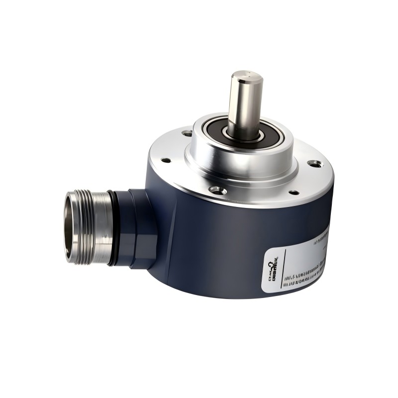
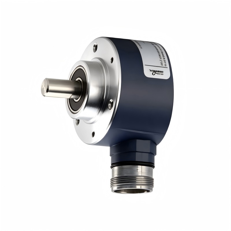
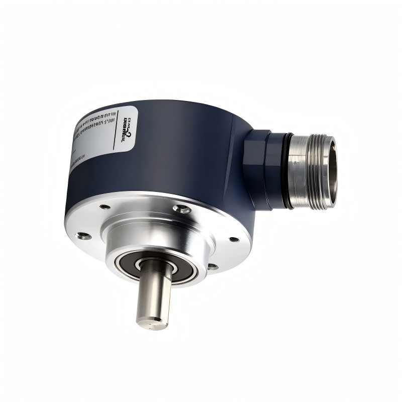
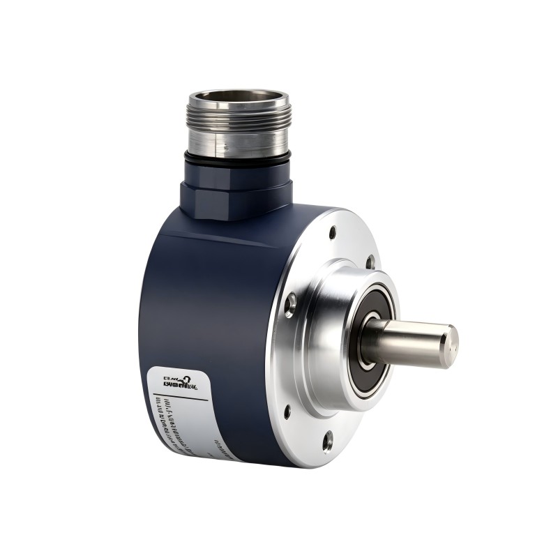
- Schneider
- XCC-2510PS81KB
- XCC Single-Turn Absolute Encoder
- France
- 58 mm
- 0.465 kg
- Xiamen, China
- New & In Stock
- T/T, PayPal, Western Union
- 1 Year
- 1-3 Working Days
- DHL, UPS, TNT, FedEx and EMS.
- 24-Hour Service
- COO
- 14
Our advantage

Global Logistics
We have a 10-year logistics and express cooperation agreement, so our products can be shipped to any place in the world.

Brand new and original
Our products are imported in bulk from the place of origin. Because of the cooperative relationship, our products are all original and 100% new.

24-hour service
We provide 7*24 hours service to our customers. We will be there whenever you need us.

Price advantage
All our products are priced very favorably because we have our own warehouse and supply.
| Company Information | |||
| [email protected] | |||
| Mobile | +8615980777398 | ||
| +8615980777398 | |||
| 15980777398 |
Product Overview
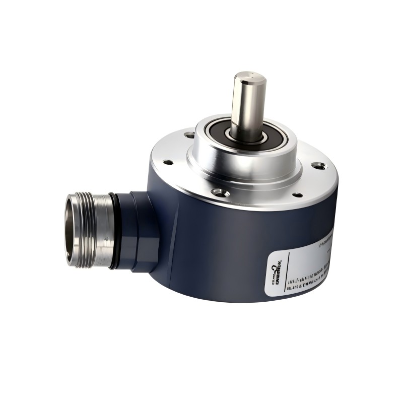
The Schneider Electric XCC-2510PS81KB Single-Turn Absolute Encoder is an industrial rotary position sensor designed to provide absolute angular position feedback in automation and motion-control systems. It belongs to the OsiSense XCC encoder family and is designed for applications where a controller needs to identify the actual shaft position within one complete revolution.
Unlike an incremental encoder, which generates pulses representing movement and generally requires a reference procedure to establish position, an absolute encoder assigns a unique digital position value to each angular position. This allows the control system to determine the shaft’s position directly from the encoder output, including after a power interruption, provided the mechanical position has not changed and the system is correctly configured.
The XCC2510PS81KB features a 58 mm housing diameter and a 10 mm solid shaft. Its 13-bit binary Push-Pull output provides 8,192 distinct position values per revolution. The encoder operates from an 11–30 V DC supply and uses a radial 16-pin M23 male connector.
This model is designed for industrial equipment requiring rotary position feedback, including machine mechanisms, indexing systems, automated handling equipment, and rotating assemblies. Its compact cylindrical construction and industrial protection characteristics make it suitable for installation in appropriately designed machinery.
The encoder is an important feedback component rather than a motor drive or standalone controller. It provides position information to a compatible PLC, motion controller, or other receiving device. Correct electrical interface selection, mechanical alignment, and signal configuration are essential for reliable operation.
Technical Specifications
| Parameter | Specification |
|---|---|
| Brand | Schneider Electric |
| Product Family | OsiSense XCC |
| Model | XCC-2510PS81KB |
| Product Type | Single-Turn Absolute Rotary Encoder |
| Encoder Design | Solid Shaft |
| Housing Diameter | 58 mm |
| Shaft Diameter | 10 mm |
| Resolution | 13-bit |
| Number of Position Values | 8,192 points per revolution |
| Output Type | Push-Pull |
| Output Coding | Binary |
| Supply Voltage | 11–30 V DC |
| Electrical Connection | Radial M23 male connector |
| Connector Configuration | 16 pins |
| Maximum Rotational Speed | 9,000 rpm |
| Maximum Output Frequency | 100 kHz |
| Maximum Output Current | 20 mA |
| No-Load Current Consumption | 0–100 mA |
| Enclosure Protection | IP65 / IP67 |
| Operating Temperature | -20 to +90 °C |
| Storage Temperature | -30 to +95 °C |
| Housing Material | Zamak |
| Base Material | Aluminium |
| Shaft Material | Stainless Steel |
| Radial Shaft Load | 10 daN maximum |
| Axial Shaft Load | 5 daN maximum |
| Dimensions Provided | 58 mm diameter |
| Weight Provided | 0.465 kg |
Specifications describe the XCC2510PS81KB configuration. Confirm the encoder’s nameplate and connector details before replacement, especially when comparing it with other XCC output variants.
Function and Working Principle
The XCC-2510PS81KB converts mechanical shaft rotation into an absolute digital position signal. Its internal optical sensing and electronic processing system determine the angular position of the shaft and provide the corresponding binary output.
1. Absolute Position Detection
The encoder assigns a unique digital value to each position within a complete revolution. With a 13-bit resolution, it can distinguish 8,192 positions over 360 degrees.
The approximate angular increment is:
[
\frac{360^\circ}{8192} \approx 0.04395^\circ
]
This resolution allows a control system to monitor relatively small changes in shaft position. Actual positioning accuracy also depends on encoder accuracy, mechanical installation, shaft coupling, controller processing, and the overall machine design.
2. Binary Output Processing
The XCC2510PS81KB uses a 13-bit binary Push-Pull output. The encoder communicates its position through digital output signals that can be interpreted by a compatible receiving device.
Binary coding provides a numerical representation of shaft position. The controller converts the received signal into an angular or machine-position value according to the configured scaling and mechanical relationship.
The receiving interface must support the encoder’s output characteristics, voltage levels, timing, and connection requirements.
3. Push-Pull Output Stage
The Push-Pull output stage is designed to actively drive both high and low signal states. This can provide a more direct digital interface than some open-collector arrangements.
However, Push-Pull outputs are not interchangeable with every encoder input. The PLC or controller input must be compatible with the encoder’s electrical specifications, including supply voltage, signal thresholds, current limits, and wiring arrangement.
4. Position Feedback After Power Interruption
An absolute encoder provides a position value rather than relying solely on accumulated movement pulses. This is useful in machines where knowing the shaft’s position after a restart is important.
The encoder does not automatically guarantee that the entire machine retains its process state. If the shaft moves while the encoder or controller is unpowered, the control system must read the current position and determine whether the machine sequence requires revalidation.
5. Continuous Position Monitoring
During operation, the encoder can provide position information to a controller for monitoring, sequencing, and motion coordination.
The controller can use this information to determine whether a mechanism has reached a target position, whether a rotating assembly is moving as expected, or whether a machine operation should proceed to its next stage.
Role in Industrial Automation Systems
The XCC-2510PS81KB is typically installed as a feedback device within a larger control architecture. Its primary role is to provide shaft-position information to a compatible electronic control system.
PLC Position Feedback
A programmable logic controller can receive encoder signals through a compatible digital input or dedicated encoder interface. The PLC then processes the position value and uses it in machine logic.
For example, a PLC-controlled indexing machine may use the encoder to confirm that a rotating table has reached a specified angular position before activating the next operation.
The receiving hardware must be designed for the encoder’s 13-bit binary Push-Pull signal. A standard digital input module should not be assumed to support this interface without verification.
Motion Controller Integration
Motion controllers use position feedback to coordinate mechanical movement. An absolute encoder can provide the position reference needed for monitoring and sequencing.
The XCC2510PS81KB may be considered for applications where its resolution, output type, rotational speed, and mechanical arrangement meet the system requirements.
Before integration, verify the controller’s supported encoder interface and whether additional signal-conditioning or interface equipment is required.
HMI and Operator Monitoring
An HMI can display position information processed by the PLC or motion controller. Operators may use this information to monitor machine status, check operating positions, or identify abnormal movement.
The encoder itself does not provide an operator display. Position information must first be interpreted by the receiving control system.
Machine Synchronization
In multi-stage machinery, encoder feedback can help coordinate rotating equipment with other machine operations. A controller may use shaft position to trigger a cutting, filling, inspection, or transfer operation at a specific point in the machine cycle.
The effectiveness of this arrangement depends on mechanical accuracy, controller response time, and the encoder’s electrical interface.
Industrial Applications
The Schneider XCC-2510PS81KB is designed for industrial rotary position sensing. Its single-turn absolute measurement and 13-bit binary output make it relevant to machinery that requires position information within one revolution.
1. Rotary Indexing Tables
Rotary indexing tables move workpieces between several processing or assembly stations. The encoder can provide shaft-position feedback to help the controller identify the table’s angular position.
The PLC can use this information to coordinate clamping, machining, inspection, and transfer operations.
2. Packaging Machinery
Packaging equipment often uses rotating mechanisms for feeding, sealing, filling, and product positioning. Absolute position feedback can help synchronize these operations with the machine sequence.
The encoder’s resolution and maximum rotational speed should be checked against the required cycle rate and mechanical arrangement.
3. Automated Material Handling
Rotating transfer mechanisms, positioning platforms, and handling equipment may require position feedback to coordinate movement.
An absolute encoder can provide a position value to the control system, helping it determine the orientation of a rotating mechanism or the position of a driven shaft.
4. Industrial Assembly Equipment
Automated assembly machines may use rotary mechanisms to position components during production. The encoder can provide feedback for indexing, alignment, and sequence control.
The controller must be configured to interpret the 13-bit binary signal correctly.
5. Machine Tools and Auxiliary Rotary Axes
Some machine tools and auxiliary rotary mechanisms require position monitoring for indexing or angular reference applications.
The XCC2510PS81KB may be considered where its single-turn measurement, output interface, shaft arrangement, and accuracy characteristics meet the machine requirements. Applications requiring multi-turn position tracking need a suitable multi-turn encoder instead.
6. General Industrial Machinery
The encoder can also be used in compatible rotating machinery where absolute shaft position is required. Typical examples include rotary actuators, automated adjustment mechanisms, and industrial positioning assemblies.
Final selection should consider shaft loading, rotational speed, environmental exposure, mounting geometry, and the receiving controller’s electrical interface.
Installation and System Integration
Proper installation is essential for reliable position measurement and long-term mechanical performance.
1. Mechanical Mounting
The encoder has a 58 mm housing diameter and a 10 mm solid shaft. Confirm that the mounting arrangement, shaft coupling, and machine geometry match the encoder’s mechanical design.
The encoder shaft should be aligned carefully with the driven shaft. Excessive radial or axial loading can affect bearing life and measurement reliability.
Use a suitable coupling to accommodate the installation’s alignment requirements. Avoid transmitting unnecessary mechanical force from the driven equipment to the encoder shaft.
2. Electrical Supply
The XCC2510PS81KB requires an 11–30 V DC supply. Confirm that the available power supply remains within the permitted range during normal operation and under expected load conditions.
Observe the specified polarity and grounding arrangement. Incorrect supply connections may damage the encoder or prevent it from operating correctly.
3. M23 Connector and Cable Selection
This model uses a radial 16-pin M23 male connector. The mating cable or connector must match the pin configuration and electrical requirements.
Do not select a cable solely because its connector has the same external size. Check the pin assignment, signal conductors, shielding, and cable construction against the product documentation.
4. PLC or Controller Interface
The receiving device must support the 13-bit binary Push-Pull output. Confirm that its input circuitry can correctly interpret the signal levels and output timing.
If the PLC does not provide a compatible encoder input, a suitable interface module or signal-conditioning device may be necessary.
5. Signal Wiring and Electromagnetic Compatibility
Keep encoder signal wiring separated from motor power cables and other sources of electrical interference where required. Use appropriate shielding and grounding practices.
Secure the cable to prevent vibration or repeated mechanical movement from stressing the connector. Ensure that the connector is correctly seated and protected against contamination.
6. Commissioning and Functional Testing
After installation, verify the supply voltage, signal wiring, shaft direction, and position values.
Rotate the shaft through a controlled range and confirm that the receiving controller reads the expected binary position changes. Check that the displayed position changes smoothly and that the controller interprets the full single-turn range correctly.
Record the encoder model, wiring arrangement, controller settings, and mechanical installation details for future maintenance.
Compatible System Components
The XCC-2510PS81KB is used with compatible automation equipment that can supply power and process its digital position signals.
| Component | Function | Compatibility Considerations |
|---|---|---|
| PLC | Processes position information and executes machine logic | Must support the encoder’s 13-bit binary Push-Pull output |
| Motion controller | Uses position feedback for motion coordination | Verify supported input interface and signal characteristics |
| 11–30 V DC power supply | Provides encoder operating power | Maintain the specified voltage range and correct polarity |
| M23 mating connector | Connects the encoder to the control system | Must match the 16-pin radial connector and pin assignment |
| Encoder cable | Carries power and position signals | Check conductor layout, shielding, and cable length |
| Signal interface module | Adapts encoder signals where necessary | Confirm electrical and timing compatibility |
| HMI | Displays position information | Normally receives processed data through the PLC or controller |
| Shaft coupling | Connects the encoder to the rotating mechanism | Match the 10 mm solid shaft and installation tolerances |
| Mounting bracket | Secures the encoder to the machine | Must match the housing and mounting arrangement |
These components are examples of equipment used in a complete installation. They are not necessarily supplied with the encoder.
Alternative Models and Replacement Considerations
When replacing the XCC-2510PS81KB, the most important factors are output coding, electrical interface, shaft dimensions, resolution, and connector configuration.
| Related Model or Option | Main Difference | Replacement Consideration |
|---|---|---|
| XCC2510PS81KGN | Push-Pull, 13-bit Gray output | Output coding differs from the binary KB version |
| XCC2510PS81SBN | SSI, 13-bit binary output | Uses an SSI interface rather than the KB Push-Pull output |
| XCC2510PS81SGN | SSI, 13-bit Gray output | Different output interface and coding |
| XCC2506PS81KB | 58 mm family, smaller solid shaft | Shaft diameter and mechanical mounting differ |
| XCC2514TS81KB | Through-shaft encoder configuration | Mechanical design and shaft arrangement differ |
The related XCC variants may share a similar housing family, but they should not be considered electrically interchangeable.
Before selecting a replacement, verify:
- Full model number and output suffix.
- Single-turn or multi-turn measurement requirement.
- Resolution and output coding.
- Push-Pull or SSI electrical interface.
- Supply voltage and output signal characteristics.
- Shaft diameter and shaft type.
- Connector type, pin count, and pin assignment.
- Mounting geometry and allowable shaft loads.
- Maximum rotational speed.
- Environmental protection requirements.
- Compatibility with the receiving PLC or motion controller.
A replacement with the same housing diameter may still require wiring changes or a different controller input module.
Key Advantages
Absolute Position Measurement
The encoder provides an absolute position value within one revolution, allowing the receiving control system to identify shaft position without relying solely on accumulated incremental pulses.
13-Bit Resolution
With 8,192 position values per revolution, the encoder supports detailed rotary position monitoring for suitable industrial applications.
Binary Push-Pull Output
The Push-Pull output provides a digital position signal for compatible receiving electronics. The binary coding can be processed by an appropriately configured controller.
Compact 58 mm Housing
The cylindrical 58 mm housing supports integration into machinery where installation space and mechanical mounting dimensions are important.
10 mm Solid Shaft
The solid-shaft construction provides a defined mechanical connection for suitable shaft couplings and rotating assemblies.
Industrial Protection
The specified IP65 and IP67 protection characteristics support use in appropriately designed industrial environments when the connector and installation are correctly assembled.
Broad Automation Applications
The encoder can be used in indexing equipment, packaging machinery, rotating mechanisms, and other applications that require single-turn absolute position feedback.
Technical FAQs
1. What is the Schneider XCC-2510PS81KB?
It is an OsiSense XCC single-turn absolute rotary encoder designed to provide digital shaft-position feedback to industrial automation systems.
2. What is the resolution of the XCC2510PS81KB?
It has a 13-bit resolution, corresponding to 8,192 distinct position values per revolution.
3. What is the output type?
The model uses a Push-Pull output stage with 13-bit binary coding. It is different from the SSI and Gray-code versions in the same product family.
4. What supply voltage does it require?
The encoder operates from an 11–30 V DC supply. Confirm the supply polarity and voltage before connecting the device.
5. What is the shaft diameter?
It has a 10 mm solid shaft. The coupling and mounting arrangement should be selected to match this mechanical configuration.
6. What connector does this encoder use?
It uses one radial 16-pin M23 male connector. The mating connector must have the correct pin arrangement and electrical configuration.
7. What is the maximum rotational speed?
The published maximum rotational speed is 9,000 rpm. The actual permitted speed in an installation must also account for mechanical loading and the driven equipment.
8. Is the XCC2510PS81KB an incremental encoder?
No. It is a single-turn absolute encoder. It provides an absolute position value within one revolution rather than relying solely on incremental pulse counting.
9. Can it connect directly to any PLC?
No. The PLC or receiving module must support the encoder’s 13-bit binary Push-Pull output and associated electrical characteristics. A suitable interface module may be required.
10. Can the XCC2510PS81KB be replaced with an SSI encoder?
Not as a direct electrical replacement. An SSI model uses a different communication interface and requires compatible receiving hardware and wiring. Confirm the controller interface before changing encoder variants.
Procurement and Maintenance Recommendations
When purchasing the Schneider XCC-2510PS81KB, verify the complete model number rather than relying only on the XCC series designation. The KB suffix identifies a specific output configuration, and other XCC2510 variants may use Gray-code or SSI interfaces.
Check the encoder’s nameplate, connector condition, shaft condition, and mounting surfaces. Confirm whether the unit is supplied with a mating cable or connector, as these accessories may need to be sourced separately.
For replacement projects, compare the original encoder’s supply voltage, output type, resolution, shaft diameter, mounting dimensions, and connector pin assignment with the proposed replacement. A mechanically compatible encoder may still be unsuitable if its output interface differs.
During maintenance, inspect the connector seal, cable condition, mounting hardware, and shaft coupling. Keep the installation free from excessive vibration and mechanical loading. If position readings become unstable, check the supply voltage, shielding, grounding, signal wiring, and controller input configuration before replacing the encoder.
Maintain a record of the encoder’s model number, wiring diagram, controller settings, and installation details. This information can reduce troubleshooting time and help ensure that future replacement equipment matches the original system.
Conclusion
The Schneider Electric XCC-2510PS81KB OsiSense XCC Single-Turn Absolute Encoder is an industrial rotary position feedback device featuring a 58 mm housing, 10 mm solid shaft, 13-bit binary Push-Pull output, and 11–30 V DC operating supply. Its 8,192 position values per revolution support rotary position monitoring in suitable industrial machinery.
For maintenance and replacement applications, the complete output configuration is particularly important. Confirming the electrical interface, connector pin assignment, shaft dimensions, and controller compatibility helps ensure reliable integration into existing automation systems.