

ProductPRODUCT
Featured products
Contact Us
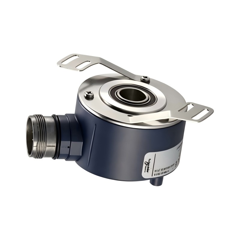
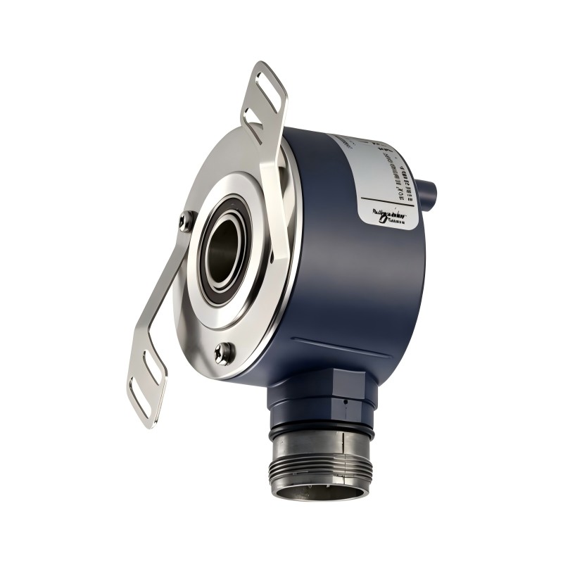
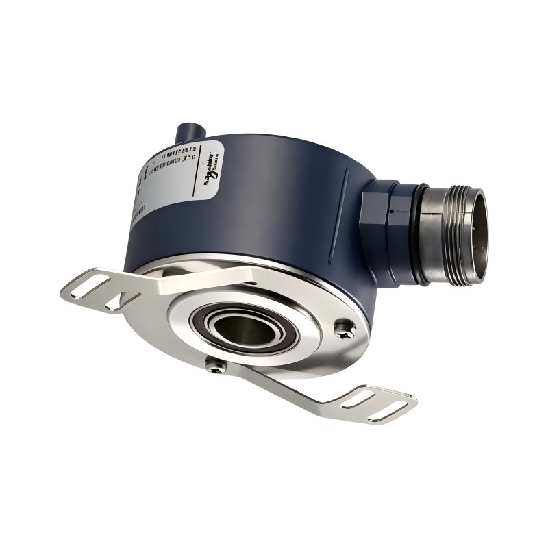
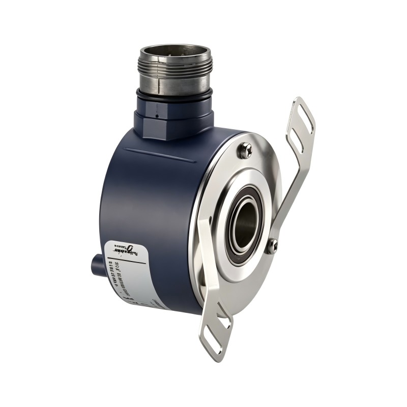
- Schneider
- XCC-1514TS03Y
- XCC Incremental Encoder
- France
- 58 mm
- 0.435 kg
- Xiamen, China
- New & In Stock
- T/T, PayPal, Western Union
- 1 Year
- 1-3 Working Days
- DHL, UPS, TNT, FedEx and EMS.
- 24-Hour Service
- COO
- 13
Our advantage

Global Logistics
We have a 10-year logistics and express cooperation agreement, so our products can be shipped to any place in the world.

Brand new and original
Our products are imported in bulk from the place of origin. Because of the cooperative relationship, our products are all original and 100% new.

24-hour service
We provide 7*24 hours service to our customers. We will be there whenever you need us.

Price advantage
All our products are priced very favorably because we have our own warehouse and supply.
| Company Information | |||
| [email protected] | |||
| Mobile | +8615980777398 | ||
| +8615980777398 | |||
| 15980777398 |
Product Overview
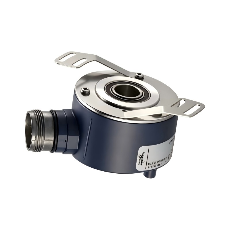
The Schneider Electric XCC-1514TS03Y Incremental Encoder is an opto-electronic rotary encoder from the OsiSense XCC product family. It is designed to provide rotational position, speed, and movement feedback in industrial automation systems. By converting shaft rotation into electrical pulse signals, the encoder allows PLCs, counters, motion controllers, and other compatible devices to monitor the movement of rotating machinery.
The XCC-1514TS03Y features a 58 mm housing diameter and a 14 mm through-shaft design. Its resolution is 360 points per revolution, making it suitable for applications that require incremental rotational feedback without the complexity of an absolute-position encoder. The Type Y output stage uses a push-pull driver, and the rated supply voltage ranges from 5 to 30 V DC.
The encoder provides three output channels and supports an output frequency of up to 300 kHz. Its maximum rotational speed is 6,000 rpm. Electrical connection is made through a 12-pin radial M23 male connector, allowing it to be integrated into compatible industrial control wiring systems.
Mechanical construction is an important part of this model’s design. The encoder uses a Zamak enclosure, an aluminum base, a stainless-steel shaft, and 6803ZZ ball bearings. Its IP65 protection rating makes it suitable for industrial environments where protection against dust and water jets is required, provided that the connector and installation are also correctly protected.
The XCC-1514TS03Y can be used in packaging machinery, conveyors, material-handling systems, printing equipment, and other automated machines requiring rotational feedback. Before installation, engineers should verify the encoder’s output interface, supply voltage, shaft dimensions, and resolution against the receiving controller.
Technical Specifications
| Parameter | Specification |
|---|---|
| Brand | Schneider Electric |
| Product Family | OsiSense XCC |
| Model | XCC-1514TS03Y |
| Product Type | Incremental Rotary Encoder |
| Encoder Principle | Opto-electronic |
| Housing Diameter | 58 mm |
| Shaft Type | Through Shaft |
| Shaft Diameter | 14 mm |
| Resolution | 360 points per revolution |
| Output Stage | Type Y |
| Output Type | Push-Pull Driver |
| Rated Supply Voltage | 5–30 V DC |
| Electrical Connection | M23 Radial Male Connector |
| Connector Configuration | 12 Pins |
| Number of Output Channels | 3 |
| Maximum Output Frequency | 300 kHz |
| Maximum Rotational Speed | 6,000 rpm |
| Maximum Output Current | 40 mA |
| No-Load Current Consumption | 0–75 mA |
| Shaft Tolerance | H7 |
| Enclosure Material | Zamak |
| Base Material | Aluminum |
| Shaft Material | Stainless Steel |
| Bearing Type | 6803ZZ |
| Protection Rating | IP65 |
| Operating Temperature | -30°C to +100°C |
| Storage Temperature | -30°C to +85°C |
| Maximum Axial Load | 2 daN |
| Maximum Radial Load | 5 daN |
| Dimensions | 58 mm housing diameter |
| Weight | 0.435 kg |
Function and Working Principle
The XCC-1514TS03Y converts mechanical rotation into electrical pulse signals. These signals are processed by an external controller to determine the movement and rotational behavior of connected equipment.
1. Optical Rotation Detection
The encoder uses an opto-electronic sensing principle to detect shaft rotation. As the connected shaft turns, the internal optical sensing system generates electrical signals corresponding to the rotational movement.
The output signals are sent to a receiving device, such as a PLC high-speed counter or encoder interface. The controller can then process the pulses to calculate movement, rotational speed, or relative position.
This arrangement allows the encoder to provide feedback without requiring the controller to measure the rotating shaft directly.
2. Incremental Position Measurement
Unlike an absolute encoder, an incremental encoder generates pulses as the shaft rotates. Position is calculated by counting these pulses from a known reference point.
The XCC-1514TS03Y provides 360 points per revolution. This resolution determines the number of output points generated during one complete shaft rotation.
For example, a controller can use the accumulated pulse count to estimate how far a conveyor roller, feed mechanism, or rotating machine component has moved.
Because the device is incremental, the controller generally needs a reference or homing procedure when the system starts if an accurate machine position must be established.
3. Push-Pull Output Operation
The Type Y output stage uses a push-pull driver. This output arrangement actively drives the output signal in both high and low states, allowing it to interface with compatible electronic inputs.
The rated supply voltage is 5–30 V DC. The receiving device must support the encoder’s output voltage characteristics and current requirements.
The push-pull interface should not be assumed to be interchangeable with every NPN, PNP, open-collector, or RS-422 input. The electrical specifications of both devices must be checked before connection.
4. Three-Channel Signal Generation
The encoder provides three output channels. These signals allow the receiving controller to process rotational feedback and determine movement information according to the connected input architecture.
The controller’s encoder input configuration must match the available signals and electrical characteristics. Correct wiring and signal interpretation are important for avoiding incorrect counts or unstable feedback.
5. High-Speed Signal Processing
The maximum output frequency is 300 kHz, while the maximum mechanical rotational speed is 6,000 rpm.
These specifications define important operating limits. The controller must have sufficient input-frequency capability to process the encoder signals at the actual operating speed.
The selected resolution, rotational speed, and controller input frequency should be evaluated together when designing a high-speed motion-control system.
Role in Industrial Automation Systems
The XCC-1514TS03Y acts as a feedback device within an industrial control architecture. It provides rotational information that helps controllers coordinate motors, conveyors, machine mechanisms, and production processes.
PLC Feedback Integration
A PLC equipped with a compatible high-speed counter or encoder input can receive the encoder’s pulse signals. The controller processes these signals to monitor shaft movement, calculate speed, or track relative position.
For example, a conveyor system may use the encoder to measure roller rotation and estimate the distance traveled by a product.
The PLC input must support the encoder’s 5–30 V DC supply and push-pull output characteristics. Input frequency capacity must also be sufficient for the intended operating speed.
Variable Frequency Drive Coordination
In motor-control applications, encoder feedback can help an automation system monitor actual mechanical movement. A PLC or motion controller can compare the measured speed with the desired speed and adjust the motor command where the system architecture supports this function.
The XCC-1514TS03Y is an incremental encoder, not a drive itself. Its signals must be connected to an appropriate controller or feedback interface.
Motion and Position Monitoring
The encoder can be installed on a rotating shaft to provide movement information to a machine controller. This is useful for equipment that needs repeatable rotation monitoring, product feeding, or synchronization between mechanical sections.
The 360-point resolution should be evaluated against the required measurement accuracy. If an application requires finer position information, a higher-resolution encoder may be more appropriate.
Machine Diagnostics
Rotational feedback can also help identify operating abnormalities. A controller may detect unexpected speed changes, missing pulses, or differences between commanded and measured movement.
Such monitoring can support maintenance activities and help operators identify mechanical or control problems before they affect the production process.
Industrial Applications
The Schneider Electric XCC-1514TS03Y is suitable for industrial machinery requiring incremental rotational feedback. Its mechanical construction, push-pull output, and IP65 protection rating support a range of automation applications.
1. Conveyor Systems
Conveyors use rotating rollers, shafts, and drive mechanisms to transport products through production lines. An incremental encoder can monitor roller rotation and provide movement information to the PLC.
The controller can use this feedback to coordinate conveyor speed with upstream and downstream equipment.
2. Packaging Machinery
Packaging machines often require controlled feeding, cutting, indexing, and product positioning. The encoder can provide rotational feedback from feed rollers or other rotating mechanisms.
The PLC can use pulse counts to coordinate machine movements with the production sequence.
3. Printing Equipment
Printing machinery relies on synchronized movement between rollers and material-handling components. Rotational feedback helps the controller monitor the movement of mechanical sections and maintain coordination.
The encoder’s resolution and maximum speed should be evaluated against the machine’s actual operating requirements.
4. Material-Handling Equipment
Automated material-handling systems may use rotary feedback to monitor rollers, feeding mechanisms, and rotating components.
The XCC-1514TS03Y can provide incremental movement information to a compatible control system, supporting automated sequencing and speed monitoring.
5. Cutting and Processing Machines
Cutting and processing equipment often needs to coordinate material movement with mechanical operations. An encoder can provide feedback on the rotation of feed rollers or other driven components.
The controller can use the pulse signals to monitor material movement and synchronize the machine cycle.
6. General Industrial Automation
The encoder can also be used in automated assembly equipment, production machinery, and rotating mechanical systems where relative position or speed feedback is required.
Its suitability depends on the required resolution, shaft arrangement, electrical interface, operating speed, and environmental conditions.
Installation and System Integration
Correct installation is essential for accurate feedback and reliable encoder operation.
1. Verify Shaft Compatibility
The XCC-1514TS03Y uses a 14 mm through-shaft configuration. Before installation, confirm that the machine shaft diameter and mounting arrangement are compatible.
The encoder’s shaft tolerance is H7. Mechanical alignment should be checked carefully to avoid excessive radial or axial loading.
The specified maximum loads are 2 daN axial and 5 daN radial. These limits should not be exceeded during installation or operation.
2. Check the Mounting Arrangement
The housing diameter is 58 mm. Confirm that the mounting bracket, shaft clearance, and surrounding mechanical components provide adequate space.
The encoder should be mounted securely while avoiding unnecessary mechanical stress. Misalignment between the encoder and the rotating shaft can increase bearing wear and affect measurement reliability.
3. Verify Electrical Supply
The rated supply voltage is 5–30 V DC. Confirm that the selected power supply provides a suitable voltage within this range and has sufficient current capacity.
The no-load current consumption is specified as 0–75 mA. The complete circuit should also account for the connected output load and controller input requirements.
4. Connect the M23 Interface
The encoder uses a 12-pin radial M23 male connector. Select a compatible female connector and cable assembly.
Follow the applicable wiring diagram rather than assigning signals based only on wire color or connector appearance. Incorrect connections may damage the encoder or the receiving equipment.
5. Match the Push-Pull Output
The Type Y push-pull output must be compatible with the receiving controller’s input circuit.
Check the high-level and low-level output characteristics, maximum output current, and input thresholds. Do not connect the encoder to an incompatible RS-422 or open-collector interface without an appropriate interface arrangement.
6. Configure the PLC or Controller
Configure the receiving device for incremental encoder signals and the correct resolution. The controller must support the required input frequency.
At the maximum specified output frequency of 300 kHz, the input hardware must be capable of processing the signal without losing pulses.
7. Test the Encoder
After installation, rotate the shaft manually or operate the machine at a safe test speed. Confirm that the controller receives stable pulse signals and that the measured direction and speed are consistent with the mechanical movement.
Check for signal interruption, incorrect counting, excessive vibration, or abnormal bearing noise before returning the machine to normal production.
Compatible System Components
The XCC-1514TS03Y is typically integrated with other industrial automation components. The following equipment may be used in a suitable installation, depending on the control architecture.
| Component | Function | Compatibility Considerations |
|---|---|---|
| PLC | Processes encoder signals and executes machine logic | Must support compatible push-pull inputs and required frequency |
| High-speed counter module | Counts encoder pulses | Confirm voltage thresholds and maximum input frequency |
| Motion controller | Processes rotational feedback | Verify encoder interface and signal configuration |
| Variable frequency drive | Controls motor speed | Encoder feedback connection requires a compatible drive or external controller interface |
| 5–30 V DC power supply | Supplies the encoder | Select a stable voltage within the rated range |
| M23 female connector | Connects the encoder to the control cable | Must match the 12-pin radial male connector |
| Encoder cable | Transfers output signals | Select suitable shielding, length, and industrial cable construction |
| Mounting bracket | Secures the encoder mechanically | Must match the 58 mm housing and mounting arrangement |
| Rotating shaft or coupling | Transfers mechanical rotation | Verify 14 mm through-shaft compatibility and alignment |
These components are examples of equipment that may be used in a complete system. They are not necessarily included with the encoder.
Alternative Models and Replacement Considerations
The OsiSense XCC family includes incremental encoders with different resolutions, output stages, and mechanical configurations. When selecting a replacement for the XCC-1514TS03Y, engineers should compare more than the housing diameter.
| Related Model | Resolution | Output Type | Important Difference |
|---|---|---|---|
| XCC1514TS01Y | 100 points | Push-pull | Lower resolution |
| XCC1514TS03Y | 360 points | Push-pull | Original model |
| XCC1514TS05Y | 500 points | Push-pull | Higher resolution |
| XCC1514TS10Y | 1,000 points | Push-pull | Higher resolution |
| XCC1514TS11Y | 1,024 points | Push-pull | Higher resolution |
| XCC1514TS03X | 360 points | 5 V RS-422 | Different electrical output interface |
A replacement should be checked for:
- Housing diameter and mounting arrangement.
- Through-shaft design and shaft diameter.
- Resolution per revolution.
- Output stage and electrical interface.
- Rated supply voltage.
- Connector type and pin configuration.
- Maximum output frequency.
- Maximum rotational speed.
- Protection rating and operating temperature.
- Controller input compatibility.
The XCC1514TS03X is not automatically interchangeable with the XCC1514TS03Y. Although both have a 360-point resolution, their output interfaces differ. The receiving controller must be compatible with the replacement encoder’s electrical characteristics.
Key Advantages
58 mm Industrial Housing
The 58 mm housing provides a standardized mechanical format for installations designed around the corresponding XCC encoder dimensions.
360-Point Incremental Resolution
The 360-point resolution provides rotational feedback for applications requiring position and speed monitoring.
Push-Pull Output
The Type Y output stage provides an active push-pull signal interface for compatible controller inputs.
Wide Supply Voltage Range
The 5–30 V DC rated supply range offers flexibility when integrating the encoder into suitable industrial control circuits.
Three Output Channels
The three-channel configuration supports rotational feedback processing by compatible encoder input devices.
High-Speed Operation
The encoder supports a maximum rotational speed of 6,000 rpm and an output frequency of up to 300 kHz, subject to correct system configuration.
IP65 Protection
The IP65 rating provides protection against dust ingress and water jets under the specified test conditions. Correct connector installation and cable sealing remain important.
Industrial Mechanical Construction
The Zamak enclosure, aluminum base, stainless-steel shaft, and 6803ZZ bearings provide a mechanical structure designed for industrial encoder applications.
Technical FAQs
1. What is the Schneider Electric XCC-1514TS03Y?
It is an incremental rotary encoder from the OsiSense XCC series. It converts shaft rotation into electrical pulse signals for monitoring rotational speed and relative position in industrial automation systems.
2. What is the resolution of the XCC-1514TS03Y?
Its resolution is 360 points per revolution. The controller uses the generated pulses to calculate rotational movement and speed.
3. What is the shaft diameter?
The encoder uses a 14 mm through-shaft design. Confirm the machine shaft and mounting arrangement before installation.
4. What output type does this encoder use?
It uses a Type Y push-pull output stage. The receiving controller must support the encoder’s output voltage and signal characteristics.
5. What is the rated supply voltage?
The rated supply voltage is 5–30 V DC. Use a suitable regulated supply and verify the electrical connection diagram before wiring.
6. What connector does the encoder use?
It uses one 12-pin radial M23 male connector. A compatible female connector and correctly wired cable assembly are required.
7. What is the maximum operating speed?
The specified maximum rotational speed is 6,000 rpm. The controller’s input-frequency capability must also be sufficient for the selected resolution and operating speed.
8. Is the XCC-1514TS03Y waterproof?
It has an IP65 protection rating, which provides protection against dust and water jets under specified conditions. It should not be treated as suitable for immersion or unrestricted exposure to water.
9. Can it connect directly to any PLC?
No. The PLC must have a compatible encoder input or high-speed counter interface. The input voltage, push-pull signal characteristics, pin assignment, and maximum counting frequency must all be checked.
10. Can the XCC1514TS03X replace the XCC1514TS03Y?
Not automatically. Both models have a 360-point resolution, but the Type X model uses a 5 V RS-422 output interface, while the Type Y model uses a push-pull output. Confirm controller compatibility before selecting a substitute.
Procurement and Maintenance Recommendations
When purchasing the Schneider Electric XCC-1514TS03Y, verify the complete model designation and confirm that the encoder has the required 58 mm housing, 14 mm through-shaft, 360-point resolution, and Type Y push-pull output.
For replacement projects, pay particular attention to the electrical interface. An encoder with the same diameter and resolution may still be incompatible if it uses a different output stage or connector arrangement.
Inspect the housing, shaft, bearings, and connector before installation. Check for physical damage, contamination, excessive shaft play, or signs of moisture ingress. Confirm that the supplied connector and cable assembly match the installation requirements.
During operation, monitor signal stability and mechanical alignment. Excessive vibration, shaft loading, or incorrect coupling can shorten bearing life and affect feedback accuracy. Keep the connector properly secured and maintain the environmental protection required by the application.
For critical machinery, retain the encoder’s wiring information, controller configuration, and replacement details as part of the equipment maintenance documentation.
Conclusion
The Schneider Electric XCC-1514TS03Y OsiSense incremental encoder is a 58 mm opto-electronic rotary encoder featuring a 14 mm through-shaft, 360-point resolution, and Type Y push-pull output. Its 5–30 V DC supply range, three output channels, 300 kHz maximum output frequency, and IP65 protection rating make it suitable for a range of industrial rotational-feedback applications.
For reliable integration, engineers should verify shaft alignment, connector wiring, output compatibility, and controller input frequency. Matching these electrical and mechanical requirements is essential when installing or replacing the XCC-1514TS03Y in an industrial automation system.