

ProductPRODUCT
Featured products
Contact Us
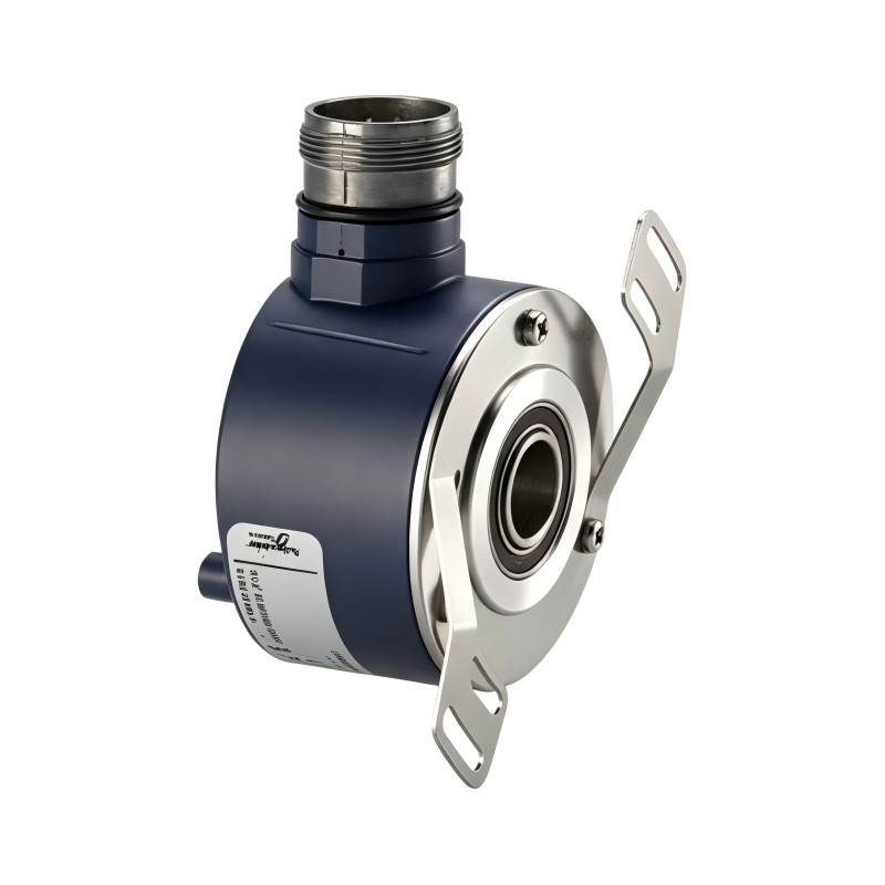
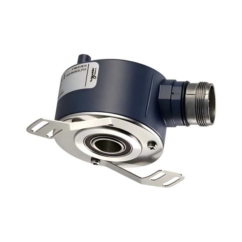
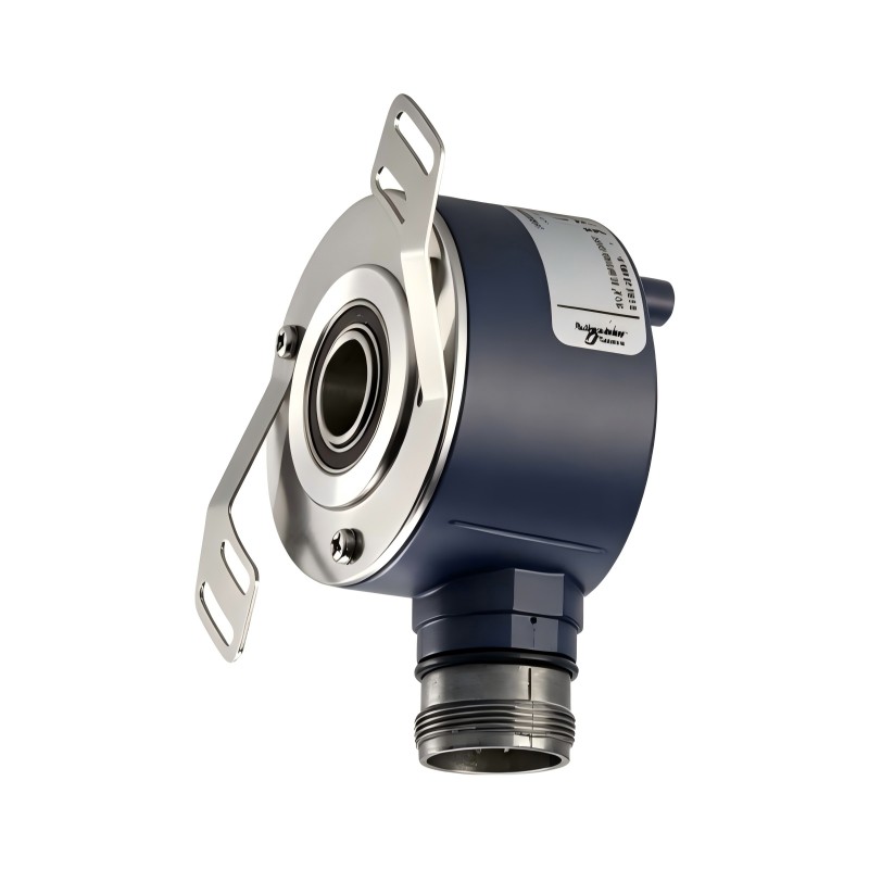
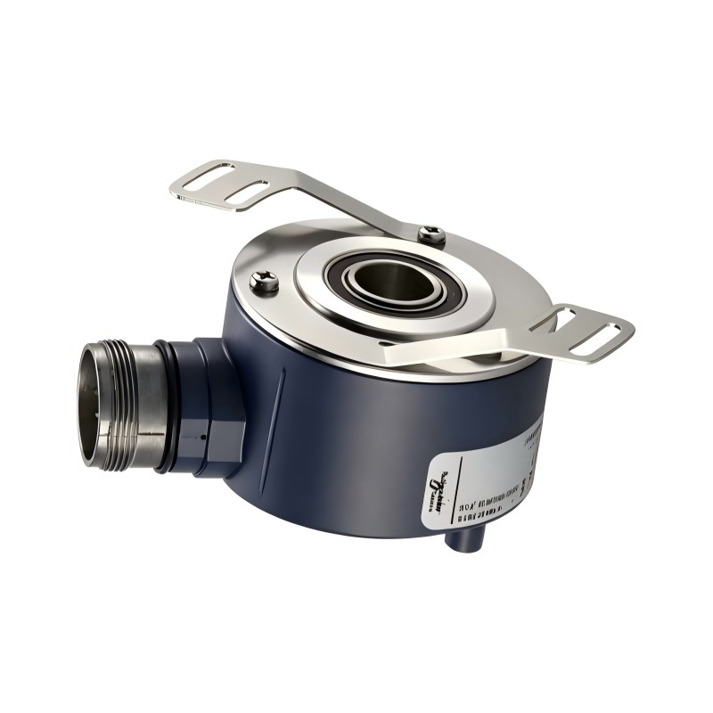
- Schneider
- XCC-1514TS03X
- XCC Incremental Encoder
- France
- 58 mm
- 0.435 kg
- Xiamen, China
- New & In Stock
- T/T, PayPal, Western Union
- 1 Year
- 1-3 Working Days
- DHL, UPS, TNT, FedEx and EMS.
- 24-Hour Service
- COO
- 14
Our advantage

Global Logistics
We have a 10-year logistics and express cooperation agreement, so our products can be shipped to any place in the world.

Brand new and original
Our products are imported in bulk from the place of origin. Because of the cooperative relationship, our products are all original and 100% new.

24-hour service
We provide 7*24 hours service to our customers. We will be there whenever you need us.

Price advantage
All our products are priced very favorably because we have our own warehouse and supply.
| Company Information | |||
| [email protected] | |||
| Mobile | +8615980777398 | ||
| +8615980777398 | |||
| 15980777398 |
Product Overview
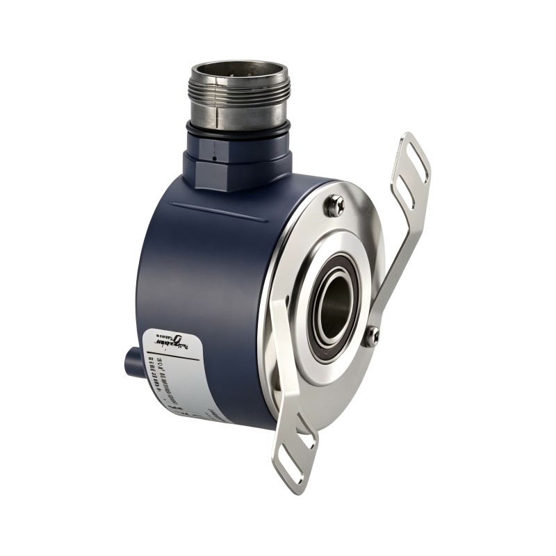
The Schneider Electric XCC-1514TS03X Incremental Encoder is an industrial rotary encoder designed to provide rotational position and speed feedback to automation and motion-control systems. It belongs to the OsiSense XCC series, a product family developed for position measurement, speed monitoring, and counting applications in industrial machinery.
An incremental encoder converts mechanical rotation into electrical pulse signals. A PLC, motion controller, counter, or other compatible device processes these signals to determine rotational movement, estimate speed, and track relative position. This feedback is important in applications where motors, conveyors, rollers, shafts, and other rotating components must operate in coordination.
The XCC-1514TS03X features a 58 mm housing diameter and a 14 mm through shaft. Its resolution is 360 points per revolution, and its Type X output stage uses a 5 V RS-422 differential interface. The encoder has a radial M23 male connector with 12 pins and supports a supply voltage range of 4.75–30 V DC according to the product documentation.
The through-shaft construction allows the encoder to be mounted around a compatible rotating shaft. This design is useful in machinery where the encoder must measure the movement of an existing shaft without requiring a separate solid-shaft coupling arrangement. An anti-rotation device is included in the encoder assembly.
The Type X output configuration is an important selection detail. It should not be confused with the Type Y push-pull version, even though the two versions share a similar mechanical design. The connected controller must support the required RS-422 differential signals.
The XCC-1514TS03X is suitable for industrial systems requiring incremental rotary feedback, including conveyor equipment, packaging machinery, material-handling systems, and general manufacturing automation. Since the XCC series has been discontinued, accurate identification and electrical compatibility checks are important when sourcing replacement units.
Technical Specifications
| Parameter | Specification |
|---|---|
| Brand | Schneider Electric |
| Product Family | OsiSense XCC |
| Model | XCC-1514TS03X |
| Catalog Reference | XCC1514TS03X |
| Product Type | Incremental Rotary Encoder |
| Housing Diameter | 58 mm |
| Shaft Type | Through Shaft |
| Shaft Diameter | 14 mm |
| Resolution | 360 points per revolution |
| Output Stage | Type X |
| Output Interface | 5 V RS-422 Differential |
| Supply Voltage Range | 4.75–30 V DC |
| Electrical Connection | Radial M23 Male Connector |
| Connector Configuration | 12 Pins |
| Number of Output Channels | 3 |
| Maximum Output Frequency | 300 kHz |
| Maximum Rotational Speed | 6,000 rpm |
| Shaft Tolerance | H7 |
| Enclosure Protection | IP65 |
| Housing Material | Zamak |
| Base Material | Aluminium |
| Shaft Material | Stainless Steel |
| Bearing Type | 6803ZZ |
| Maximum Axial Load | 2 daN |
| Maximum Radial Load | 5 daN |
| Operating Temperature | -30°C to +100°C |
| Storage Temperature | -30°C to +85°C |
| Dimensions Provided | Diameter: 58 mm |
| Weight | 0.435 kg |
| Product Lifecycle | Discontinued |
Note: Electrical characteristics and operating limits should be checked against the documentation supplied with the exact unit. Confirm the connector pinout and receiving-device requirements before installation.
Function and Working Principle
The XCC-1514TS03X operates through optical incremental measurement. As the connected shaft rotates, the encoder detects changes in the position of an internal coded element and generates electrical pulses corresponding to the movement.
The receiving controller processes these pulses to calculate relative movement and rotational speed.
1. Incremental Position Measurement
An incremental encoder generates a series of pulses as its shaft rotates. Each pulse represents a defined amount of angular movement.
With a resolution of 360 points per revolution, the XCC-1514TS03X generates 360 output points for one complete shaft revolution under the specified counting convention.
A PLC or counter can use the pulse count to estimate how far a shaft or connected machine component has moved. For example, a conveyor controller can use encoder feedback to monitor belt movement or compare actual movement with a commanded operating condition.
Unlike an absolute encoder, an incremental encoder does not independently retain an absolute mechanical position after power loss. If absolute machine position is required, the control system may need a reference or homing procedure.
2. Rotational Speed Measurement
The frequency of the encoder’s output pulses changes according to shaft speed.
When the shaft rotates faster, the encoder produces pulses at a higher frequency. The receiving controller can measure this frequency and calculate rotational speed.
This function is useful for monitoring motors, rollers, conveyors, and other rotating equipment. Speed feedback can also help a controller detect abnormal operating conditions, such as unexpected slowing or loss of rotation.
3. RS-422 Differential Signal Transmission
The Type X output stage uses a 5 V RS-422 differential interface. Differential transmission uses complementary signal pairs to improve resistance to electrical interference compared with single-ended signal transmission.
This is useful in industrial environments where encoder cables may be installed near motor conductors, drives, contactors, and other sources of electrical noise.
The receiving device must support the appropriate RS-422 input standard. Signal wiring, cable shielding, grounding, and connector pin assignments should follow the manufacturer’s instructions.
4. Through-Shaft Mechanical Measurement
The 14 mm through-shaft design allows the encoder to be fitted around a compatible rotating shaft.
This arrangement can simplify installation in machinery where the shaft is already part of the mechanical assembly. The encoder housing must be secured using the specified mounting and anti-rotation arrangement so that it does not rotate with the shaft.
Correct alignment is essential. Excessive shaft loading, mechanical vibration, or incorrect mounting can affect bearing life and measurement reliability.
5. Three-Channel Feedback
The encoder has three output channels. These provide the signals required by compatible control equipment for incremental measurement and direction-related processing.
The receiving controller’s configuration must match the encoder’s output type and signal arrangement. Incorrect channel wiring can result in unreliable counting, incorrect direction interpretation, or failure to detect movement.
Role in Industrial Automation Systems
The XCC-1514TS03X acts as a feedback sensor within an industrial control architecture. It converts mechanical rotation into electrical information that can be interpreted by a PLC, counter, motion controller, or other compatible device.
PLC Position Feedback
A PLC can receive encoder pulses through a compatible high-speed counter or encoder input interface. The controller processes the pulse count to calculate relative movement and coordinate machine operations.
For example, a packaging machine may use encoder feedback to track the movement of a feed roller. The PLC can compare the measured movement with the required production sequence and coordinate cutting, sealing, or labeling operations.
The PLC input must support the encoder’s RS-422 differential output. A standard digital input should not be assumed to accept this signal directly.
Speed Monitoring
The encoder can provide speed information to a control system by measuring the frequency of its output pulses.
A controller can use this information to monitor rotating equipment, compare actual speed with a reference value, and identify deviations from normal operating conditions.
This is useful in systems where stable rotational speed is important for product quality or equipment coordination.
Motion Synchronization
Multiple rotating components may need to operate at coordinated speeds or positions. Encoder feedback can help the control system monitor the movement of individual shafts and compare their relative operation.
In a conveyor production line, for example, encoder signals can support synchronization between material-feeding equipment and downstream processing stations.
Equipment Condition Monitoring
Encoder feedback can also contribute to basic equipment monitoring. Unexpected pulse loss, inconsistent speed, or movement deviations may indicate mechanical or electrical problems.
Such monitoring depends on the controller’s diagnostic logic and the quality of the encoder installation. The encoder itself does not provide a complete machine-condition monitoring system.
Industrial Applications
1. Conveyor and Material-Handling Systems
Conveyors use rotating rollers, drive shafts, and motors to move materials through production and distribution processes.
The XCC-1514TS03X can provide rotational feedback for compatible conveyor shafts. The PLC can process encoder pulses to estimate belt movement, monitor speed, and coordinate material transfer between production stages.
Its through-shaft design can be useful where the encoder is mounted around an existing shaft.
2. Packaging Machinery
Packaging equipment often requires accurate control of film movement, feed rollers, and product transportation.
An incremental encoder can provide feedback for monitoring roller rotation and coordinating machine operations. The 360-point resolution provides a defined pulse reference for compatible counting and speed-measurement applications.
The final measurement accuracy depends on the mechanical transmission ratio, controller counting method, and installation arrangement.
3. Printing and Processing Equipment
Printing and continuous-processing machines often require coordinated movement between rollers and material-feed mechanisms.
Encoder feedback can help the control system monitor rotational speed and relative movement. This information can support synchronization between different machine sections and help reduce process inconsistencies.
4. Cutting and Length-Measurement Systems
Industrial cutting machines may use rotary feedback to estimate material movement before a cutting operation is triggered.
The encoder generates pulses corresponding to shaft rotation. A compatible controller can convert the pulse count into a calculated material length using the roller circumference and mechanical transmission ratio.
Accurate results depend on roller diameter, slip conditions, encoder resolution, and controller configuration.
5. Cranes and Material-Handling Equipment
Rotary feedback may be used in selected crane and material-handling mechanisms to monitor shaft movement or rotational speed.
The encoder’s mounting arrangement, vibration resistance, mechanical loading, and environmental protection should be evaluated for the specific installation.
Where the application is safety-related, the XCC-1514TS03X should not be treated as a safety-rated position sensor unless the complete system documentation explicitly establishes that capability.
6. General Manufacturing Automation
The encoder can be used in compatible machinery requiring incremental position or speed feedback. Examples include feed mechanisms, rotating tables, rollers, auxiliary drive shafts, and automated production equipment.
Its suitability depends on the receiving interface, mechanical shaft arrangement, required resolution, operating speed, and environmental conditions.
Installation and System Integration
Correct installation is essential for reliable encoder feedback. Mechanical alignment, electrical compatibility, and signal wiring should all be checked before commissioning.
1. Verify the Shaft Arrangement
The XCC-1514TS03X uses a 14 mm through shaft. Before installation, measure the machine shaft and confirm that its dimensions and mechanical arrangement are suitable.
The shaft must be properly aligned with the encoder. Avoid forcing the encoder onto a shaft that is oversized, damaged, or incorrectly positioned.
The included anti-rotation device should be installed according to the manufacturer’s instructions. It helps prevent the encoder housing from rotating with the measured shaft.
2. Check Mechanical Loading
The encoder has specified maximum axial and radial loads. The connected shaft and mounting arrangement should remain within these limits.
Excessive side loading, shaft misalignment, or vibration can reduce bearing life and cause unstable operation.
Do not use the encoder housing as a mechanical support for unrelated machine components.
3. Confirm Electrical Compatibility
The encoder’s Type X output is a 5 V RS-422 differential interface. Confirm that the PLC, counter, or motion controller has compatible differential encoder inputs.
The supply voltage range is 4.75–30 V DC according to the product documentation. The supply arrangement must also meet the requirements of the selected output interface.
Do not connect the encoder to an input designed only for an incompatible NPN, PNP, or push-pull signal without an appropriate interface.
4. Connect the M23 Connector
The encoder uses a radial M23 male connector with 12 pins.
Use a compatible female connector and correctly rated cable. Verify the pin assignment before making connections, because incorrect wiring may prevent operation or damage connected equipment.
The cable should be routed away from high-current motor wiring and other sources of electromagnetic interference where practical.
5. Configure the PLC or Counter
The receiving device should be configured for the encoder’s resolution and RS-422 signal type.
The control system must also use the correct counting mode. Depending on whether it counts one or multiple signal edges, the effective count per revolution may differ from the catalog’s stated resolution.
If direction detection is required, configure the controller to process the appropriate incremental channels.
6. Commission the Encoder
After installation, rotate the shaft slowly and confirm that the receiving device detects the expected pulse activity.
Check the direction indication, speed measurement, pulse stability, and response at different operating speeds. Compare the measured movement with a known mechanical reference where appropriate.
If the signal is unstable, inspect connector wiring, cable shielding, grounding, mechanical alignment, and the controller’s input configuration.
Compatible System Components
The XCC-1514TS03X is intended to operate as part of a complete measurement and control system. The following components may be used depending on the machine architecture.
| Component | Function | Compatibility Considerations |
|---|---|---|
| PLC | Processes encoder feedback and controls machine sequences | Must support the encoder’s signal type through a suitable input |
| High-Speed Counter Module | Counts encoder pulses at the required frequency | Check RS-422 compatibility and maximum input frequency |
| Motion Controller | Processes position and speed feedback | Verify signal interface and supported encoder resolution |
| 24 V DC Power Supply | Provides power to compatible encoder circuits | Confirm voltage and current requirements for the actual connection |
| M23 Female Connector | Provides the electrical connection to the encoder | Must match the radial M23 male connector and pin arrangement |
| Shielded Encoder Cable | Transmits encoder signals | Select suitable cable construction and shielding |
| Mechanical Coupling or Shaft Interface | Connects the encoder to the rotating machine shaft | Confirm 14 mm through-shaft compatibility and alignment |
| Anti-Rotation Device | Prevents encoder housing rotation | Use the supplied mounting arrangement |
| HMI | Displays speed and position information | Normally receives processed information through the PLC or controller |
The encoder does not necessarily include these external components. Confirm the required connector, cable, mounting hardware, and controller interface before ordering.
Alternative Models and Replacement Considerations
The XCC-1514TS03X belongs to a discontinued encoder family. When selecting an alternative, the mechanical and electrical characteristics must be compared carefully.
| Alternative Model or Type | Main Difference | Replacement Considerations |
|---|---|---|
| Schneider XCC1514TS01X | 100-point resolution | Same general mechanical family and Type X output, but lower resolution |
| Schneider XCC1514TS05X | 500-point resolution | Higher resolution; verify controller configuration |
| Schneider XCC1514TS10X | 1,000-point resolution | Higher pulse count per revolution |
| Schneider XCC1514TS03Y | 360-point resolution with push-pull output | Different electrical output stage; not a direct electrical substitute |
| Schneider XCC1514TS03X | Original 360-point Type X model | Preferred for like-for-like replacement when mechanical and electrical condition are suitable |
When selecting a replacement, compare the following parameters:
- Housing diameter and mounting arrangement.
- Through-shaft type and 14 mm shaft diameter.
- Resolution per revolution.
- RS-422 differential or push-pull output type.
- Supply voltage range.
- Connector type and pin configuration.
- Maximum rotational speed.
- Maximum output frequency.
- Protection rating and operating temperature.
- Mechanical loading limits.
- Controller input compatibility.
A replacement encoder with a different resolution may require changes to PLC scaling, motion parameters, or machine calibration. A Type Y push-pull encoder should not be substituted for a Type X RS-422 model without confirming that the receiving device supports the different signal interface.
Key Advantages
360-Point Incremental Resolution
The encoder provides 360 points per revolution, allowing compatible control equipment to monitor relative shaft movement and rotational speed.
58 mm Industrial Housing
The 58 mm housing provides a defined mechanical format for installation in compatible industrial equipment.
14 mm Through-Shaft Design
The through-shaft arrangement allows the encoder to be mounted around a compatible rotating shaft, supporting a range of industrial mechanical layouts.
RS-422 Differential Output
The Type X output provides differential signaling for compatible controllers and can help improve signal transmission reliability in electrically noisy environments.
M23 Industrial Connector
The radial M23 male connector provides a defined electrical connection for suitable industrial encoder cables and connectors.
IP65 Protection
The specified IP65 rating provides protection against dust ingress and water jets under the applicable test conditions. Correct connector mating and installation are still necessary to maintain the intended protection.
Broad Supply Voltage Range
The documented 4.75–30 V DC supply range provides flexibility for suitable system power arrangements, subject to the requirements of the output stage and receiving equipment.
Technical FAQs
1. What is the Schneider Electric XCC-1514TS03X?
It is an OsiSense XCC incremental rotary encoder designed to measure rotational movement and speed. It has a 58 mm housing, a 14 mm through shaft, and a 360-point resolution.
2. What does the TS03X suffix mean?
The TS designation identifies the through-shaft encoder configuration, while 03 identifies the 360-point resolution. The final X indicates the 5 V RS-422 differential output type.
3. What is the resolution of this encoder?
The XCC-1514TS03X has a resolution of 360 points per revolution. The effective count used by a controller may be higher depending on its edge-counting method.
4. What output signal does the XCC-1514TS03X provide?
It uses a Type X 5 V RS-422 differential output. The receiving controller must have a compatible differential encoder input.
5. What is the supply voltage range?
The documented supply voltage range is 4.75–30 V DC. Confirm the requirements of the exact output interface and the connected controller before applying power.
6. What shaft size does this model support?
It is designed for a 14 mm through-shaft arrangement. The shaft and mounting components should be checked for dimensional compatibility before installation.
7. What connector does the encoder use?
It uses a radial M23 male connector with 12 pins. A compatible female connector and correctly wired cable are required.
8. Can it measure motor speed?
Yes. Its output pulse frequency changes with shaft speed. A compatible PLC, counter, or motion controller can calculate rotational speed from the pulse frequency.
9. Can it provide absolute position after a power interruption?
No. It is an incremental encoder and does not independently retain absolute shaft position after power loss. The machine may need to perform a homing or reference procedure before resuming position-dependent operation.
10. Is the XCC-1514TS03X still manufactured?
The Schneider Electric XCC product family is listed as discontinued. Availability of the exact model may depend on remaining stock and industrial spare-parts suppliers. Verify the complete catalog number and condition before purchasing.
Procurement and Maintenance Recommendations
When purchasing the Schneider Electric XCC-1514TS03X, verify the complete catalog reference, housing diameter, through-shaft size, resolution, output stage, supply voltage, and connector configuration.
The Type X RS-422 output is especially important. A similar-looking Type Y encoder may use a push-pull output and therefore require a different controller input arrangement. Confirm the electrical interface rather than relying only on the mechanical appearance.
For used or surplus equipment, request clear photographs of the encoder housing, shaft opening, connector, and nameplate. Check for damaged threads, bearing play, corrosion, connector deformation, and signs of impact. Where possible, request a functional test showing stable pulse output.
During routine maintenance, inspect the mechanical mounting, anti-rotation device, connector, cable shielding, and shaft alignment. Excessive vibration or mechanical loading should be corrected before it causes encoder damage.
Keep a record of the installed resolution, PLC scaling, wiring arrangement, and controller configuration. This information can simplify future replacement and reduce commissioning time.
Conclusion
The Schneider Electric XCC-1514TS03X OsiSense incremental encoder is a 58 mm industrial rotary feedback device with a 14 mm through shaft, 360-point resolution, and 5 V RS-422 differential output. Its radial M23 male connector and IP65 protection make it suitable for compatible industrial position and speed measurement applications.
For maintenance and replacement projects, the most important selection factors are resolution, output interface, supply voltage, shaft dimensions, and connector compatibility. Since the XCC series has been discontinued, careful catalog-number verification and functional testing are recommended when sourcing this encoder.